

Sensortechnik Meinsberg TM 40, AM 40, LF 40 Operating Instructions Manual
edition 13/11
Sensortechnik Meinsber g G mbH
Quality System certified to DIN EN ISO 9001
Meinsberg, Kurt-Schwabe-Straße 6
D-04736 Waldheim/Germany
Internet: www.meinsberg.de
Tel.: +49 (0) 34327 623 0
Fax: +49 (0) 34327 623 79
Draft
Operating Instruction
Manual
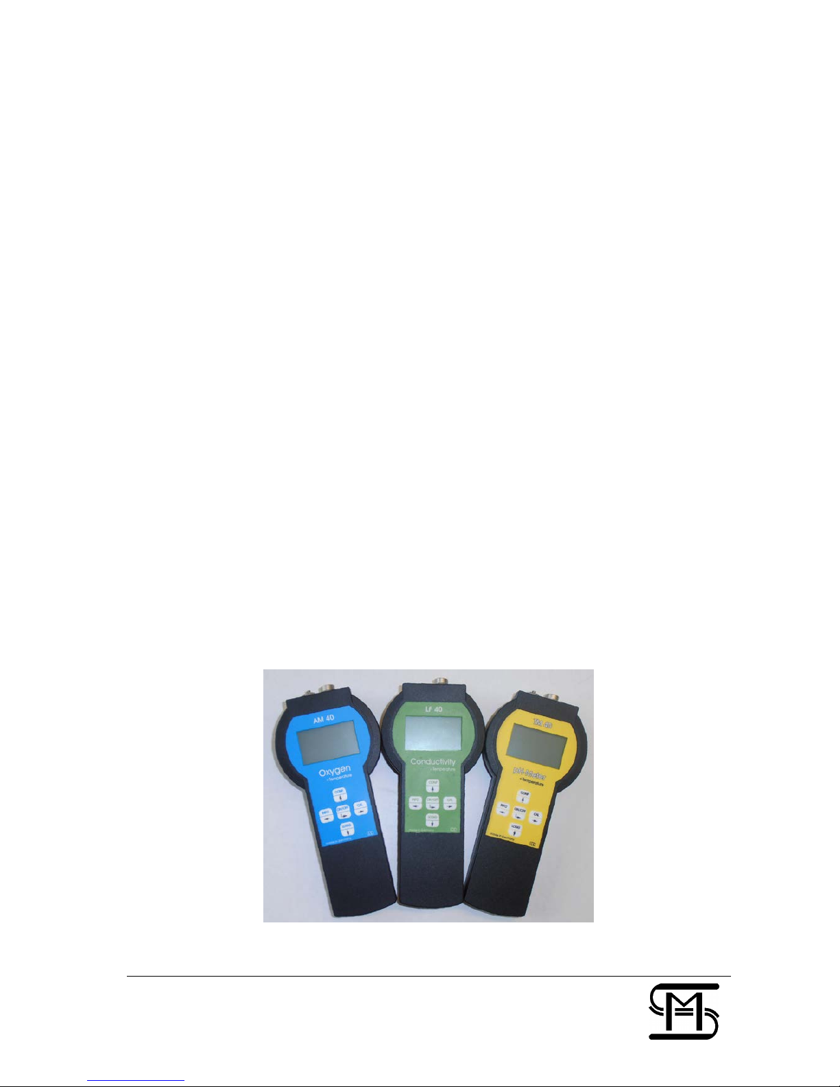
pH/Redox/ISE Meter
TM 40
Oxygen Meter
AM 40
Conductivity Meter
LF 40

1. Safety ..................................................................................................................................................................... 4
2.
Sockets ................................................................................................................................................................... 5
2.1 Battery .......................................................................................................................................................... 5
3. Button, Display, M enu structure, Password protection ........................................................................................ 6
3.1 Operation elements ..................................................................................................................................... 6
4. Configuration the basic settings “General” ........................................................................................................... 7
4.1 Configuration Backlight ............................................................................................................................... 7
4.2 Configuration pass word ............................................................................................................................. 8
4.3 Configuration clock ...................................................................................................................................... 8
4.4 Configuration language ............................................................................................................................... 8
4.5 Configuration off time .................................................................................................................................. 8
4.6 Data logger .................................................................................................................................................. 9
5. Info ........................................................................................................................................................................ 10
6. Interface HMG USB ............................................................................................................................................. 10
7. Maintenance, Disposal ........................................................................................................................................ 10
8. TM 40 ................................................................................................................................................................... 11
8.1 Application Fields TM 40 ........................................................................................................................... 11
8.2 Construction TM 40 ................................................................................................................................... 11
8.3 pH-Sensor EGA 142/TM 40 ...................................................................................................................... 11
8.4 Menu structure TM 40 ............................................................................................................................... 11
8.5 Calibration pH ............................................................................................................................................ 13
8.5.1 Data input ..................................................................................................................................... 13
8.5.2 Settings of the temperature offset ............................................................................................... 14
8.5.3 Two-point-Calibration “two point“ ................................................................................................ 14
8.5.4 Automatic Calibration .................................................................................................................. 14
8.5.5 Calibration error ........................................................................................................................... 15
8.6 Calibration Redox ...................................................................................................................................... 15
8.6.1 Data input ..................................................................................................................................... 15
8.6.2 Setting of the temperature offset ................................................................................................ 15
8.7 Calibration ISE ........................................................................................................................................... 15
8.7.1 Data input ..................................................................................................................................... 15
8.7.2 Settings of the temperature offset ............................................................................................... 15
8.7.3 Two-point Calibration „Two point“ ............................................................................................... 16
8.8 Configuration TM 40 .................................................................................................................................. 16
8.8.1 Configuration of the fix temperature ........................................................................................... 16
8.8.2 Configuration of the sensor type ................................................................................................. 17

9. AM 40 ................................................................................................................................................................... 17
9.1 Application Fields AM 40 ........................................................................................................................... 17
9.2 Construction AM 40 ................................................................................................................................... 17
9.3 Dissolved Oxygen Sensor MF 41-N/AM 40 ............................................................................................. 17
9.4 Menu structure AM 40 ............................................................................................................................... 18
9.5 Calibration oxygen ..................................................................................................................................... 19
9.5.1 Data input ..................................................................................................................................... 19
9.5.2 Settings of the Temperature Offset ............................................................................................ 20
9.5.3 Single-Point Calibration „one point“ ............................................................................................ 20
9.5.4 Automatic Calibration .................................................................................................................. 20
9.5.5 Calibration error ........................................................................................................................... 20
9.6 Configuration AM 40.................................................................................................................................. 21
9.6.1 Configuration of the fix temperature ........................................................................................... 21
9.6.2 Configuration of the main value .................................................................................................. 21
10. LF 40 .................................................................................................................................................................... 22
10.1 Application Fields LF 40 ............................................................................................................................ 22
10.2 Construction LF 40 .................................................................................................................................... 22
10.3 Conductivity Sensor LTC 0,35/LF 40 ....................................................................................................... 22
10.4 Menu structure LF 40 ................................................................................................................................ 22
10.5 Calibration conductivity ............................................................................................................................. 23
10.5.1 Data input ..................................................................................................................................... 23
10.5.2 Settings of the temperature offset ............................................................................................... 24
10.5.3 One-point-Calibration „one point“ ............................................................................................... 24
10.5.4 Automatic calibration „Automatic“ ............................................................................................... 25
10.5.5 Calibration error ........................................................................................................................... 25
10.6 Configuration ............................................................................................................................................. 25
10.6.1 Configuration of the fix temperature ........................................................................................... 25
10.6.2 Configuration of the measuring range „meas. range“ ............................................................... 25
11. Specifications ....................................................................................................................................................... 26
12. Delivery volume ................................................................................................................................................... 27
13. Accessories .......................................................................................................................................................... 27

4/27
1. Safety
This Operating Instructions Manual contains fundamental information that should be observed in connection with the
installation, start-up, operation and maintenance of the instrument in connection with the sensor. Therefore, it is absolutely
vital for the user to read this manual prior to workin g with it.
User qualification
The meter has been designed for analytical measurements. It is assumed that the user/operator and the maintenance
personnel have the proper professional skills and experience to know the specific properties of analytical measuring
systems, master the safe handling of chemicals, for example, in the maintenance of electrodes/sensors, and can assess
any dangers and risks resulting thereof. The user must ensure that the national legislation and procedures concerning the
maintenance of industrial health and safety standards, the accident preventions and the handling of chemicals are
observed.
Installation and getting started
The perfect functioning and operational safety of the instrument can only be maintained under the climatic conditions
specified in the section "Specification" of this manual. When the instrument is moved from cold to warm surroundings,
condensate may occur and interfere with the functioning of the instrument. In such case, the user should wait until the
temperature of the instrument has adapted to t he ambient temperature b efore using the instru ment again.
Use the sensor and interface cables recommended by the manufacturer only. For the sensors and accessories, the
instructions and regulations given in the respective operating instructions manuals and specification sheets will apply. The
instrument can only be operated with the battery specified in the section “ Specification”.
Be careful when connecting other instruments (e.g. via interface). Connections with external instruments may cause not
permissible potentials inside the instrument (e.g. connections between GND and earth). These potentials may result in
operational influences or malf unctions in the instrum ent itself or the ext ernal devices conne cted.
Proper usage
The meter and the sensor are intended for measuring and docu mentation of analy sis parameters. T aking into consideration
the “Specification” paragraph, operating and using the unit for this application is the proper usage. Any application beyond
this and individual modifications or extensions are improper and will lead to loss of entitlement to the warranty. When
connecting the unit with electrochemical sensors, always take into account their life and natural wear as this may result in
malfunctioning of the measuring system and the regulation or control associated therewith. The user must take suitable
measures to limit harmful effects of such malfunctioning.
General safety instructions
The complete meter has been manufactured and tested in accordance with the relevant guidelines and standards for
electronic measuring equipment. It has left the fact ory in technically unobj ectionable condition.
The perfect functioning and operational safety of the instrument and the accompanying components will only be ensured if
the user observes the normal safety precautions as well as the specific safety guidelines stated in the present manual and
in the relevant operating instruction manuals of the components. If there is reason to assume that the instrument can no
longer be employed without a risk, it must be set aside a nd appropriately marked to prevent further use.
The safety of the user may be endangered, e.g. if the instrument or one of its components
•
shows visible damage,
•
no longer operates as specified,
•
has been stored over a longer period under unsuitable conditions,
•
has been subjected to difficult conditions during transport.
If in doubt, please contact your supplier and sent back t he instrument to the manuf acturer for repair and maintenance.
5/27
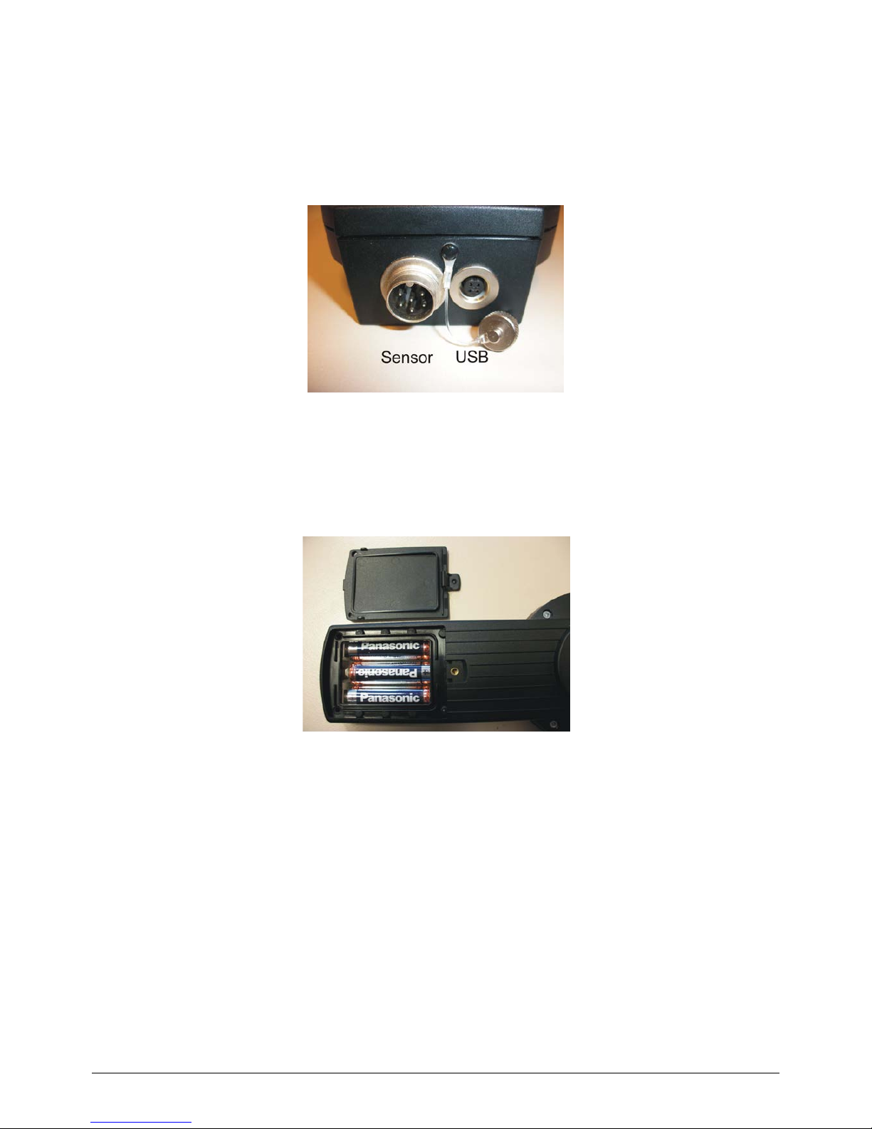
2. Sockets
2 sockets for connecting the sensor and the” Interface HMG USB” are located on the front side of the instrument. Please
use only the delivered original cable for the interface with the PC. For protecting the sockets against moisture and to avoid
corrosion, the sensor should always b e con nected to the i nstrument and the “Interface HMG USB” so cket shoul d be seale d
by means of the protection cap if it is not in use. The “Interface HMG USB” is not included in the deliv ery.
Cable Sockets
2.1 Battery
Please open the battery chamber on the back sid e of the instrument an d insert the battery correctly into the cham ber.
Battery Chamber
Please use batteries from the type AA, IEC R6, LR6 only. After connecting and inserting the battery, please close the
battery chamber carefully an d correctly, to avoid moistu re coming inside t he device.
If the battery is in low condition, the device shows these with only 1 bar in battery indicator display. A change of the battery
is recommended. If there is no bar in the display, t he battery must be cha nged immediately.
Only for AM 40:
After changing battery or sensor please note the wait time before a new calibration. We recommend a new
calibration after battery change, because the permanent polarisation of the sensor was interrupted by
disconnecting the sensor from the battery.
6/27
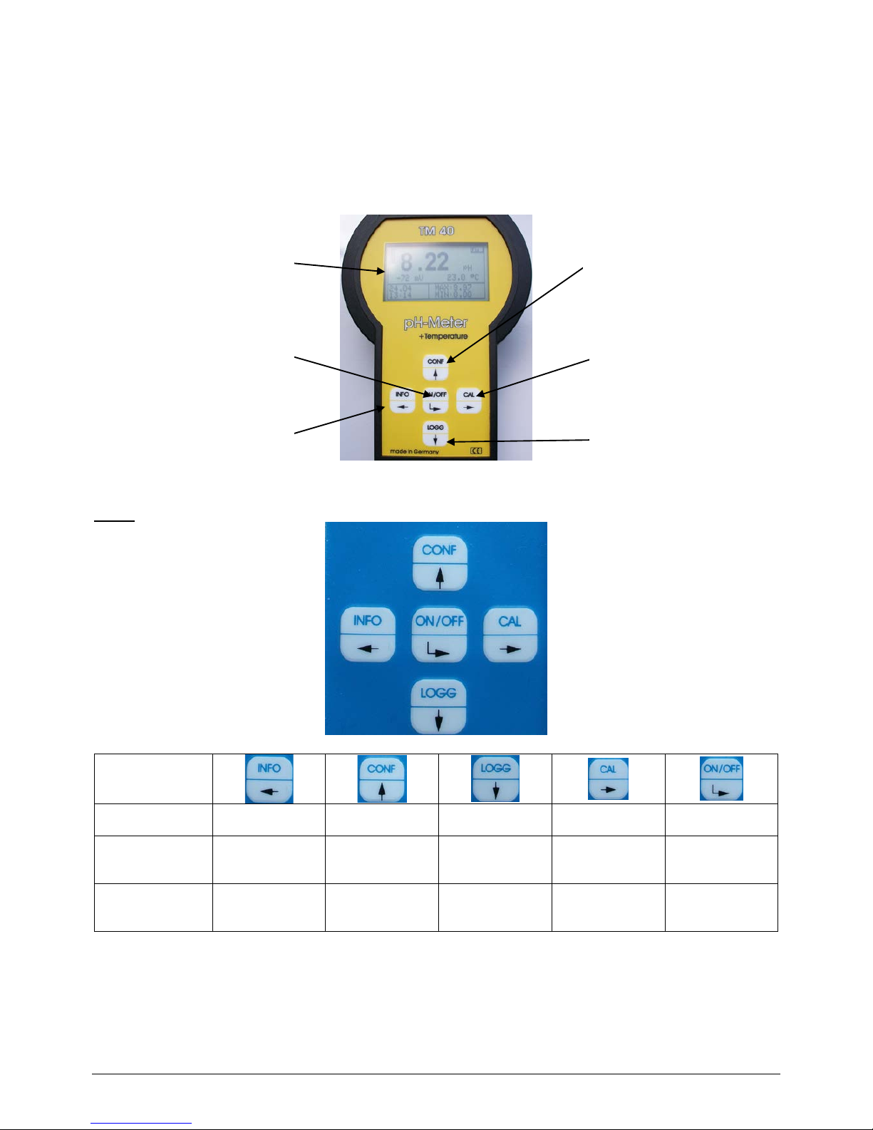
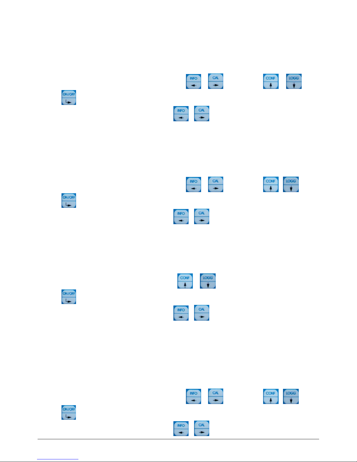
3. Button, Display, Menu structure, Password p rotection
3.1 Operation elements
The instrument features easy operation by mean s of 5 buttons only and a plain text menu structure.
Button
Open a menu Information Configuration Data logger Calibration On / Off
navigation in the
menu
Cursor left Cursor up Cursor down Cursor right
selection /
ENTER
input / change
values
Cursor left position value +1 position value -1 Cursor right
confirm / save
value
By pressing the button “ON/OFF“ the meter switches on. The meter switches off either automatically after a
preset time-out or by long (approximately 3 seconds) pressing th e “ON/OFF“ button.
Only for AM 40:
Also when the AM 40 is switched off, the connected O2-Sensor is supplied with the necessary polarisation
voltage and so the system is directly after switching on always ready to measure.
Configuration
Navigation <up>
Calibration
Navigation <right>
Data logger
Navigation <down>
Graphic display On/Off
Enter
Information
Navigation <left>
7/27
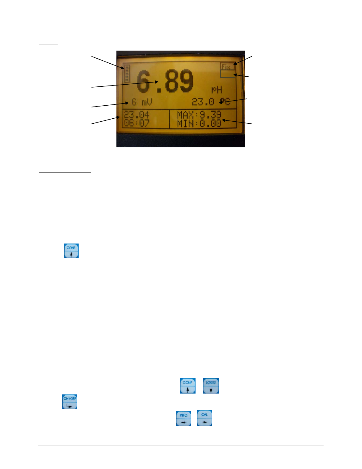
Display
Password protection
The calibration menu (CAL) and the configuration me nu (CONF) are password-protected.
The default password for opening these menus is 1.
4. Configuration the basic settings “General”
Open with
+ password t he configuration menu.
Select the menu item you would like to configure.
Backlight
Password
Clock
Language
Off time
Back
4.1 Configuration Backlight
On the device the backlight for display can be switched o n or off.
For configuration of the backlight do the following step s:
1. Open menu „general“
2. Select „Backlight“ disable/enable
Select the position you would like to use by using the buttons
or .
Press the -button to accept and save the entry.
To cancel the input dialogue without saving the value pre ss
+ .
Battery bar
display
Main
Measurement value
Second
Measurement value
Date / Time
Fix temperature active
Temperature
Min / Max
Main Measurement value
only LF 40:
Temperature compensation
nLF
8/27
4.2 Configuration pass word
For configuration of the password do the following steps:
1. Open menu „general“
2. Select „Pass word“ and enter your new pass word
3. Retry the new pass word
Select the position you would like to change by using the b uttons
or and change with or .
Press the -button to accept and save the entry.
To cancel the input dialogue without saving the val ue press
+ .
4.3 Configurati on clock
For configuration of the clock do the following steps:
1. Open menu „general“
2. Select „clock“ and enter the time and date
Select the position you would like to change by using the buttons
or and change with or .
Press the -button to accept and save the entry.
To cancel the input dialogue without saving the value press
+ .
4.4 Configuration language
For configuration of the language do the following steps:
1. Open menu „general“
2. Select “language“ and enter the language
Select the position you would like to use by using the but tons
or
Press the -button to accept and save the entry.
To cancel the input dialogue without saving the val ue press
+ .
4.5 Configuration off time
You can set the time when the meter switch es off automatically. The data logger will continue to log, if it is set in para 4.6
(Data logger).
To configuration the off tim e do the following step s:
1. Open menu „general“
2. Select “off time“ and enter the time
Select the position you would like to change by using the buttons
or and change with or .
Press the -button to accept and save the entry.
To cancel the input dialogue without saving the val ue press
+ .
9/27
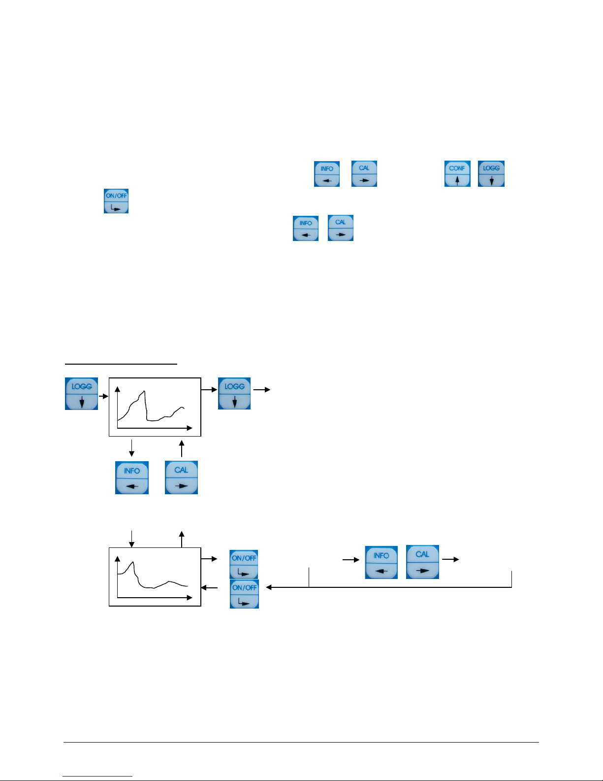
4.6 Data logger
The device has an integrated data logger with real-time clock. So it is possible to save the last about 4.000 data sets (date,
time, main measurement value, second measurement value, temperature ).
The saved data can be either displayed directly in the device display or t ransferred by the USB-interface.
To configuration the data logger d o the following steps:
1. Open menu „general“
2. Enter the time interval in the menu it em „ interval“
Select the position you would like to change by using the buttons
or and change with or .
Press the -button to accept and save the entry.
To cancel the input dialogue without saving the value pre ss
+ .
Data logger Automatic:
If the automatic is switched off, the logger logs only by switched on device. (plea se note also the off time)
If the automatic is switched on, the logger logs continue. (long time logging)
For correct logger function set the real time clock.
During view the logged data’s the recording is stopped.
Menu structure data logger
measuring-info
next period
1 period
back
back to Measuring
next measuring-info
 Loading...