

Page 1
Sensor Partners
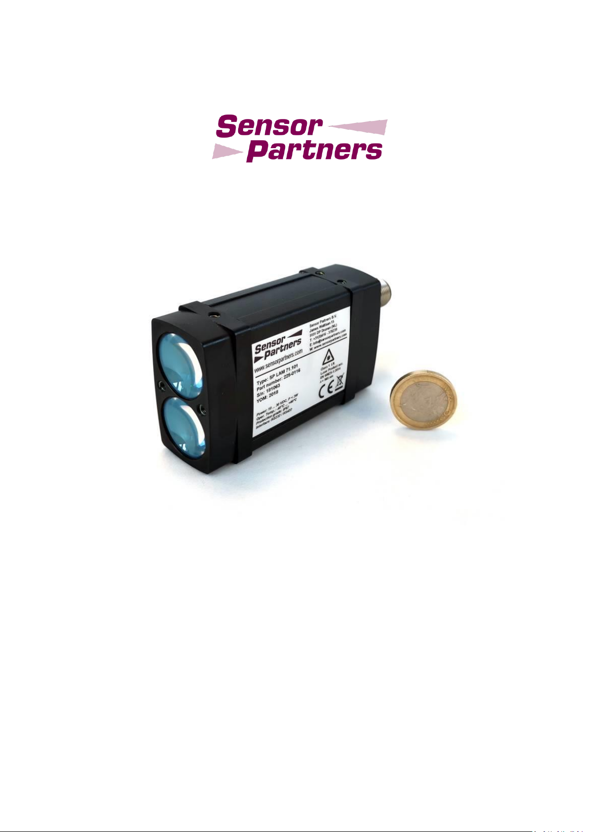
LAM71 Laser Distance Sensor
Manual
Page 2
User advice
LAM71, Release 001_Revision 001
Date
Release
Revision
Remarks/ Modifications
2018 March
001
000
Feasibility study version
2018 November
001
001
functional model
Dear User,
Please read this operating manual carefully before starting to operate the LAM71 laser distance
meter. This is the only way to make sure that you will be able to make full use of the capabilities of
your new laser distance meter, and to prevent any damage caused by operating errors.
Sensor Partners
Sensor Partners BV – Head Office
James Wattlaan 15
5151 DP Drunen
The Netherlands
Revision status:
No part of this manual may be reproduced in any form (photograph, photocopy, microfilm or any
other procedure) without the prior written permission of Sensor Partners BV, nor may contents be
processed, reproduced or distributed using electronic systems . This operating manual was produced with the appropriate care. No liability will be accepted for damage resulting from the nonobservance of the information contained in this manual. We reserve the right to modify the document following technical advancements without notice.
Page 3

Table of contents
LAM71, Release 001_Revision 001
5
1 GENERAL INFORMATION ..................................................................................................... 7
1.1 Warning signs, symbols and references .............................................................................. 7
1.2 Intended use ........................................................................................................................ 7
1.3 Integration of device in a system ......................................................................................... 7
2 SAFETY ADVICE .................................................................................................................... 8
2.1 Laser class ............................................................................................................................ 8
2.2 Basic safety advice ............................................................................................................... 8
2.3 Transport and storage ......................................................................................................... 9
2.4 Cleaning and maintenance .................................................................................................. 9
2.5 Service .................................................................................................................................. 9
3 INTENDED USE/ CONDITIONS ............................................................................................ 10
3.1 Operating and storage conditions ..................................................................................... 10
3.2 Improper use and possible error sources .......................................................................... 10
3.3 Warning signs and type plates ........................................................................................... 10
4 DEVICE DESCRIPTION ......................................................................................................... 11
4.1 General information .......................................................................................................... 11
4.2 Scope of delivery ................................................................................................................ 11
4.3 Laser beam image .............................................................................................................. 12
5 INSTALLATION AND START OF OPERATION ....................................................................... 13
5.1 Preparatory work prior to installation ............................................................................... 13
5.2 Mechanical installation ...................................................................................................... 13
5.3 Connector pin assignment ................................................................................................. 14
5.4 Serial interface RS232 / RS422 ........................................................................................... 15
6 PARAMETER SETUP AND MEASURING OPERATION .......................................................... 16
6.1 General information .......................................................................................................... 16
6.2 Measurement involving moving targets ............................................................................ 17
6.3 Identification ...................................................................................................................... 17
6.3.1 ID recognition .................................................................................................................... 17
6.3.2 ID? – Online help ............................................................................................................... 17
6.4 Operation modes ............................................................................................................... 18
6.4.1 DM – single distance measurement ................................................................................. 18
6.4.2 DT – Continuous distance measurement (distance tracking) ........................................... 18
6.5 Status ................................................................................................................................. 19
Page 4

Table of contents
6
LAM71, Release 001_Revision 001
6.5.1 TP - Internal temperature ................................................................................................. 19
6.5.2 HW – hardware status ...................................................................................................... 19
6.5.3 PA – Display Parameter setting ......................................................................................... 20
6.5.4 PR – Parameter reset ........................................................................................................ 21
6.6 Setup parameters .............................................................................................................. 22
6.6.1 AS – Autostart function ..................................................................................................... 22
6.6.2 BR – Baud rate ................................................................................................................... 22
6.6.3 DR – LAM71 restart (device reset) .................................................................................... 23
6.6.4 GN – Setup GAIN ............................................................................................................... 23
6.6.5 MF – Measurement frequency ......................................................................................... 24
6.6.6 MW – Measurement window ........................................................................................... 26
6.6.7 OF – Offset ........................................................................................................................ 27
6.6.8 QA – Analogue output ....................................................................................................... 28
6.6.9 Q1/ Q2 – Switching output ............................................................................................... 30
6.6.10 SA – Mean value average .................................................................................................. 32
6.6.11 SO – Set offset ................................................................................................................... 33
6.6.12 SD – Data format of serial interface output ...................................................................... 33
6.6.13 SE – Error mode ................................................................................................................. 36
6.6.14 ST – Select Target .............................................................................................................. 36
6.6.15 TC – Time Calibration ........................................................................................................ 37
6.6.16 TE – Terminator ................................................................................................................. 38
6.6.17 TI + TO Trigger ................................................................................................................... 39
6.6.18 UB – Unit for binary output............................................................................................... 43
7 SERIAL INTERFACE AND COMMUNICATION SOFTWARE ................................................... 44
8 ERROR PROCESSING ........................................................................................................... 45
9 TECHNICAL DATA ............................................................................................................... 46
Page 5
LAM71, Release 001_Revision 001
7
1 General information
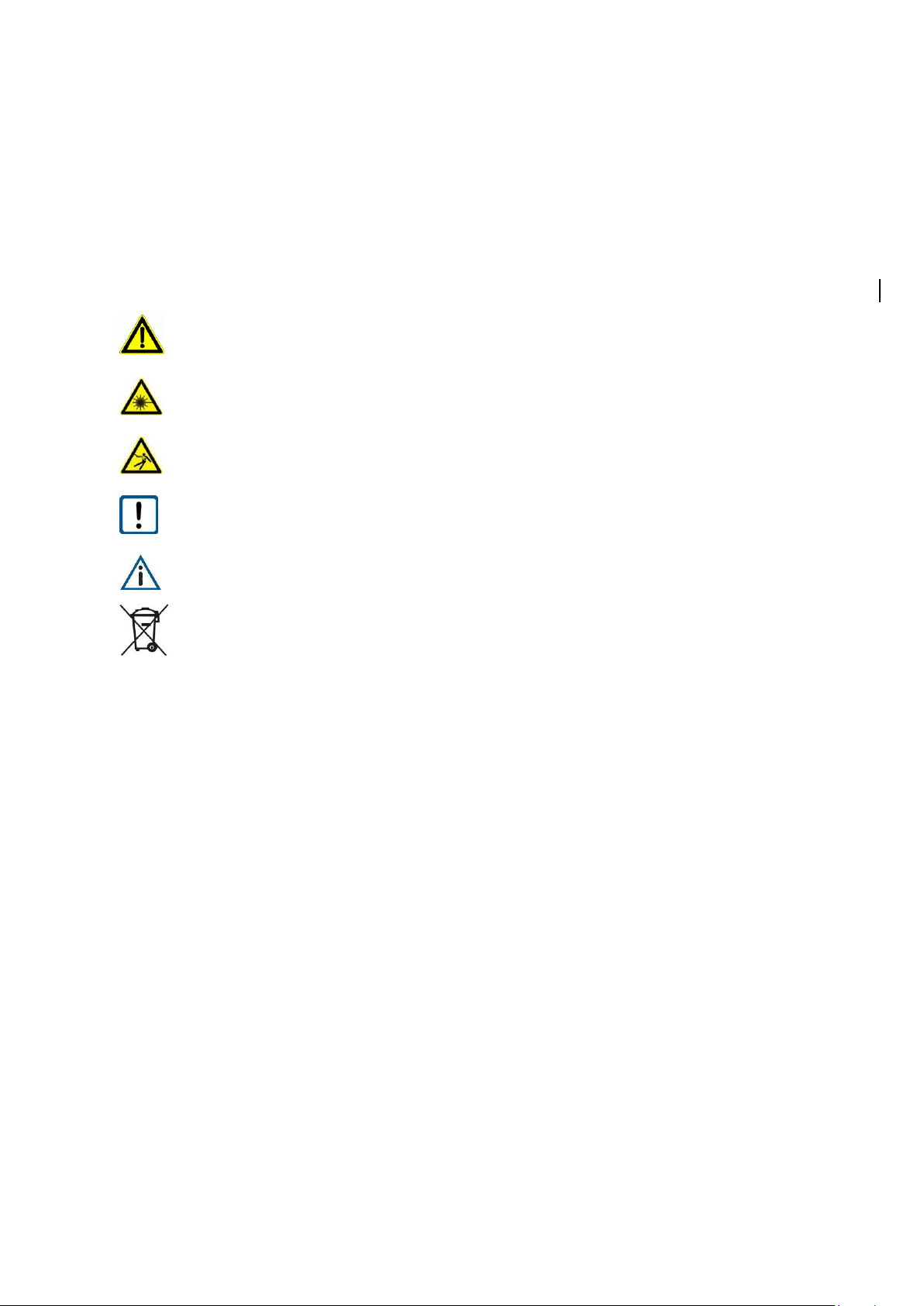
The sign Caution warns against dangers to health which may occur if this advice is not observed
The sign Laser warns against emitting visible or invisible laser radiation.
The sign Electric shock warns against the danger of an electric shock.
The sign Attention warns against possible damage to the device
The sign Information points to important information.
This sign indicates that special environmental protection guidelines must be observed when disposing of the device.
Note / important note
1.1 Warning signs, symbols and references
1.2 Intended use
The laser distance meter LAM71 is a custom built functional model. It is destined for
professionals to be used solely at research and development facilities. The customer and system integrator is responsible for compliance with the relevant guidelines, laws and standards, in particular compliance with the safety requirements.
1.3 Integration of device in a system
The combination or integration of the device, LAM71, with or into a system not provided and authorized
by Sensor Partners for the respective device may result in errors of the data transmission, including but
not limited to failures in the total measurement range, accuracy, repeatability, connectivity or transfer
speed of data. Sensor Partners assumes no liability for any damages, losses, expenses, costs, injuries,
claims or demands arising out of or in connection with the combination or integration of the device,
LAM71, with or into a system not provided and authorized by Sensor Partners for the respective device.
Page 6
8
LAM71, Release 001_Revision 001
2 Safety advice
2.1 Laser class
Based on the standard EN 60825-1:2014 the LAM71 is in correspondence with laser
class 1. The laser radiation of class 1 lasers is not dangerous to the human eye, thus,
any injury can be excluded.
2.2 Basic safety advice
Please read the safety and operating advice carefully, and observe the advice when operating the
LAM71 laser distance measurement device.
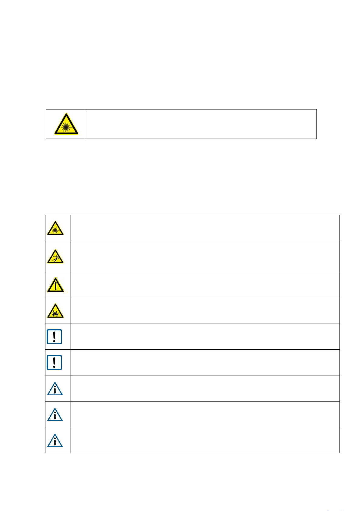
The LAM71 is equipped with a laser diode emitting in the infrared spectrum, which is not visible
to the human eye.
Ensure there is no voltage applied when establishing a connection to the device and while integrating the device into the customer system. There is a potential risk of an electric shock to the
operator or of damage to the device.
Do not operate the device if there is any damage visible. Contact customer service for further assistance.
The device may not be used in explosive environments; otherwise there is the danger of damage
to the LAM71 and the surrounding equipment, and of injuries of the user.
Observe the operating conditions for the LAM71. Adverse use can cause damage to the device
and will void the warranty.
Please consider the assembly advices when integrating the device in the system. By applying the
wrong voltage level and/or polarity to the LAM71 a permanent damage may be caused.
Avoid touching the optics and do not use the device if the optics are soiled or clouded.
Store the device in the delivered packaging.
Do not perform any modification to the device as this may cause potential harm to the operator
and the device. Any modification on the device will void the warranty.
Page 7

LAM71, Release 001_Revision 001
9
2.3 Transport and storage
The laser distance meter LAM71 is delivered in standard packaging. All kinds of transport are permitted.
It is recommended to store the unit inside the transport packaging until it is used. Please observe the
storage conditions.
2.4 Cleaning and maintenance
The LAM71 does not require any maintenance. Keep the optical glass surfaces (laser and receiver
lenses) free of deposits to ensure trouble-free measurements. Dust can be removed using an air brush.
In case of dirt which is hard to remove, please contact the manufacturer. Do not be clean the device by
using solvents or mechanical tools. Electrical, mechanical or optical modifications of the device are not
permitted!
2.5 Service
In case that repair work is necessary, please contact our After Sales and send the device to the address
below:
Sensor Partners
Sensor Partners BV – After Sales
James Wattlaan 15
5151 DP Drunen
The Netherlands
If you have any questions, please contact us via telephone or e-mail:
Page 8
10
LAM71, Release 001_Revision 001
3 Intended use/ Conditions
3.1 Operating and storage conditions
Operating temperature
- 40 °C … + 60 °C
Storage temperature
- 40 °C … + 70 °C
Humidity
15% … 90%, non-condensing
3.2 Improper use and possible error sources
• The unit may be used only as described.
• Please do not remove any labels and type plates.
• Repair work must not be performed by the user. In case of questions or doubt, the
manufacturer is to be consulted. For contact data see section 2.5.
• In order to obtain correct measuring values the following advice is to be observed:
1. Measurements against the sun or onto surfaces with low reflectivity in very bright environ-
ments can result in faulty measurements.
2. Measurements through glass, optical filters, Plexiglas or other translucent materials can re-
sult in measurement errors.
3.3 Warning signs and type plates
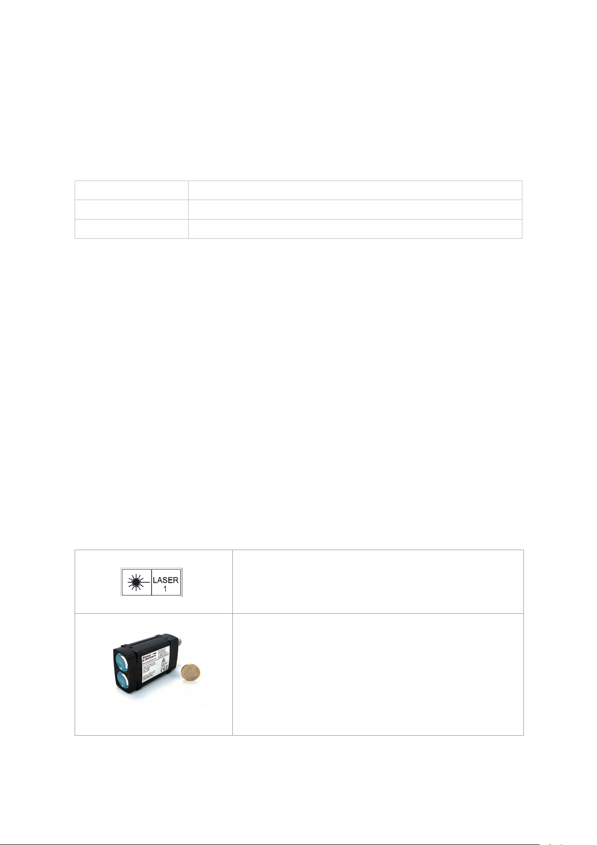
Laser label
The LAM71 works with a class 1 laser.
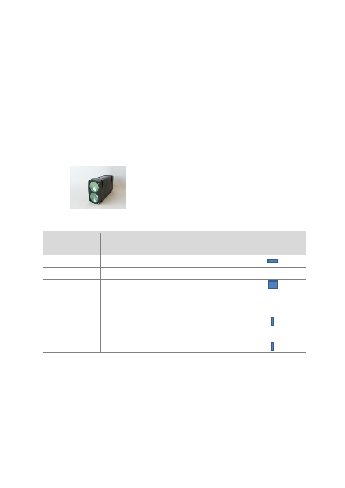
Type plate
The type plate shown is an example. Serial number (SN) may
differ from this image.
Page 9

LAM71, Release 001_Revision 001
11
4 Device description
4.1 General information
The laser distance meter LAM71 is designed as a compact range finder dedicated for easy integration.
Interface solutions like RS232, RS422, analog output and switching outputs are integrated.
LAM71 is designed for an operating temperature (ambient temperature) of as low as -40°C up to +60°C.
The heating element ensures the operating temperature of the components and free optics (no condensation) of the LAM71.
Connecting cables are available, for order numbers please see chapter 4.2.
Devices with a cable length of up to 10 m are demonstrably EMC-safe.
4.2 Scope of delivery
Designation
Part no.
Remarks
LAM71.101
225-0116
RS232 or RS42 (see connecting schema)
Accessories
Interface cable 3 m
18J25019
Interface cable 5 m
18J25020
Interface cable 10 m
18J25021
Light tube
18J25022
Device cables with angled plug-in connector are available upon request.
Page 10
12
LAM71, Release 001_Revision 001
4.3 Laser beam image
Divergence of laser
Transmitter: 2 mrad x 0.4 mrad
Receiver: 5.8 mrad
The table below shows the size of the laser spot on the target in dependence on the distance.
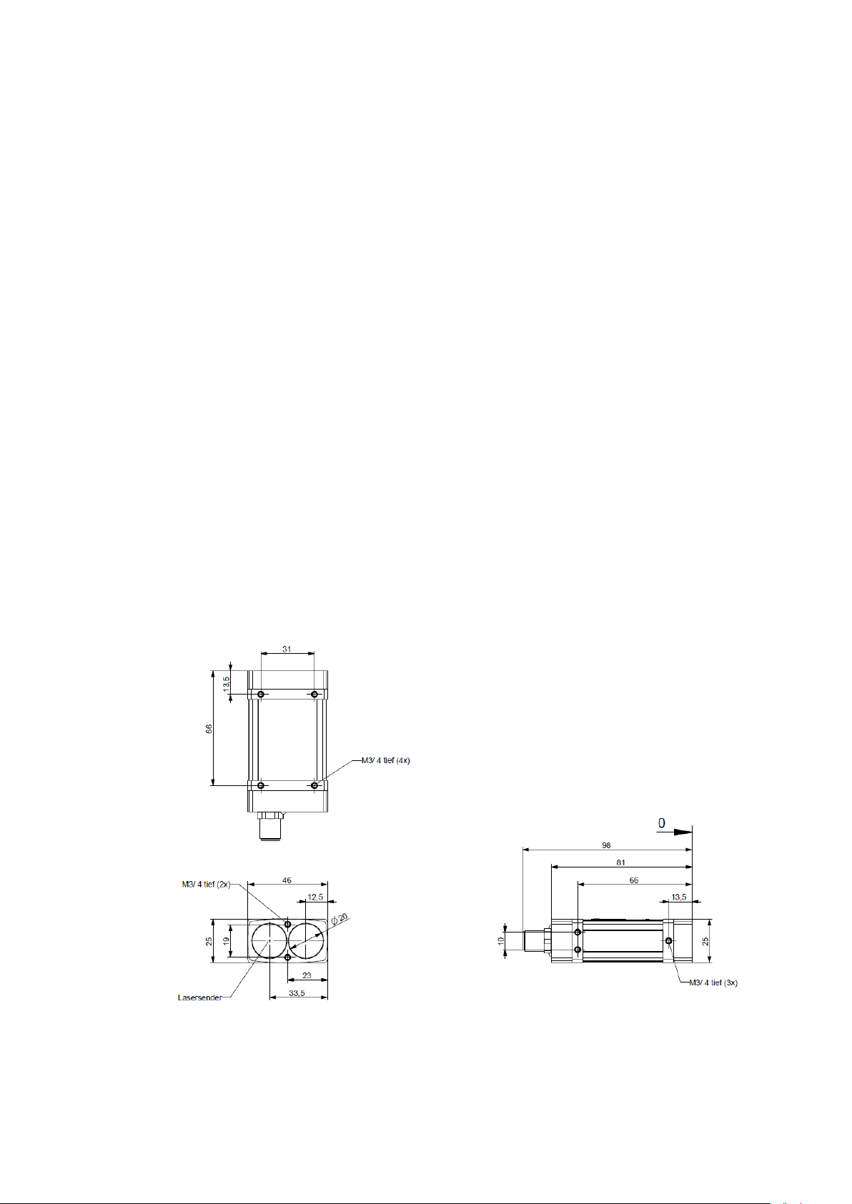
Installation of LAM71
Lenses of LAM71 are vertical about each other.
Distance
Laser spot width
Laser spot height
Footprint laser spot
(not true to scale)
0.2 m
14 mm
9 mm
1 m
14 mm
10 mm
5 m
15 mm
19 mm
10 m
17 mm
30 mm
20 m
19 mm
51 mm
70 m
32 mm
157 mm
150 m
52 mm
327 mm
270 m
87 mm
625 mm
The above-mentioned laser spot holds approx. 50 % of the entire laser energy. An aura with less energy
forms around that spot.
Page 11
LAM71, Release 001_Revision 001
13
5 Installation and start of operation
5.1 Preparatory work prior to installation
• Remove the packaging of the LAM71 and accessories.
• Check the delivery for completeness.
• Examine the device and the accessories for damage.
5.2 Mechanical installation
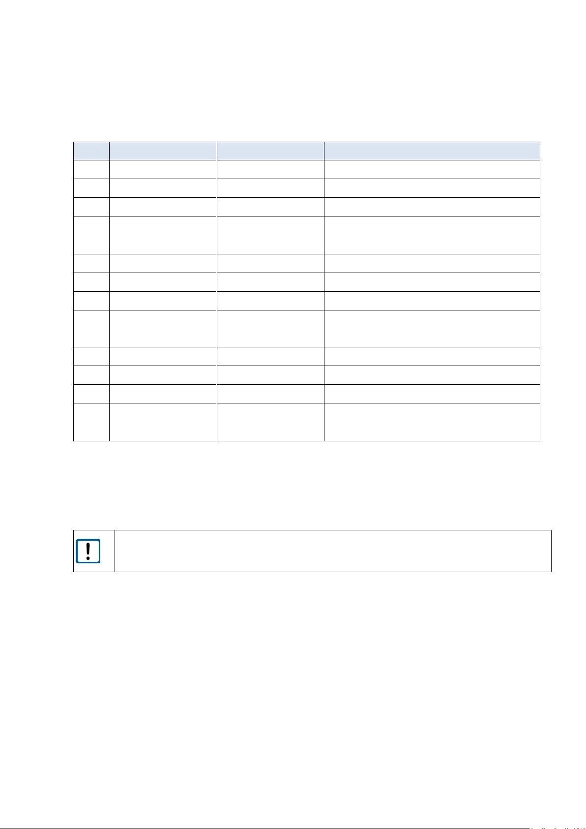
The LAM71 can be screwed on 3 positions:
- front with 2 screws M3
- bottom side with 4 screws M3
- one small side with 3 screws M3
Length to be chosen depending on the counter piece.
Recommendation: Use screws with washer and ring washer
Screws are not included in the scope of delivery.
Exact positions are shown in the picture below.
The zero point for measurement is identical with the housing front face.
0 = zero point for measurement
tief = thread depth
Lasersender = laser transmitter
Figure 1 LAM71 dimensions
Page 12
14
LAM71, Release 001_Revision 001
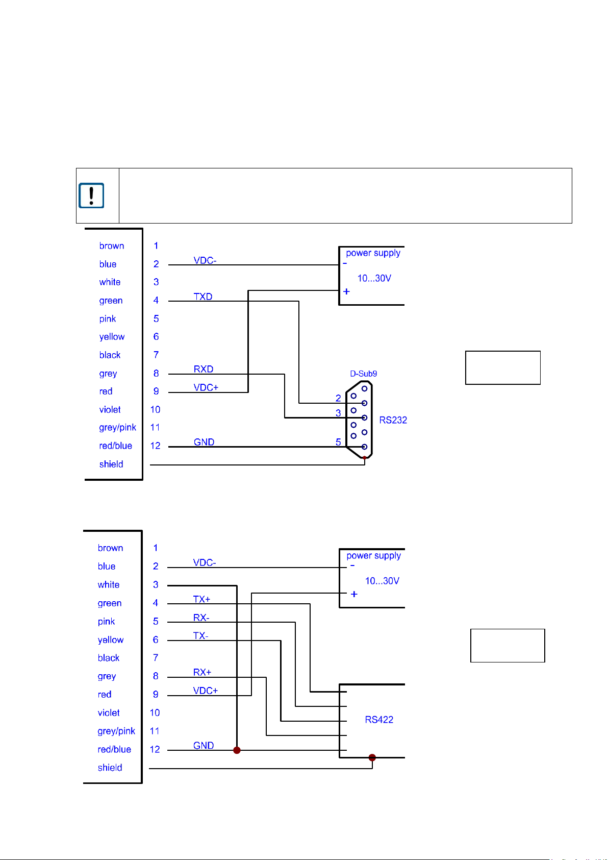
5.3 Connector pin assignment
Pin
Colour
Signal
Description
1
Brown
Q1
Switching output Q1
2
Blue
VDC-
GND of supply voltage
3
White
RS422 / RS232
Setting pin RS422 or RS232
4
Green
TX+
TXD
RS422 transmission data +
RS232 transmission data
5
Pink
RX-
RS422 receiving data -
6
Yellow
TX-
RS422 transmission data -
7
Black
Q2
Switching output Q2
8
Grey
RX+
RXD
RS422 receiving data +
RS232 receiving data
9
Red
VDC+
Supply voltage 10 … 30 V DC
10
Violet
TRIGIO
Trigger signal IN / OUT
11
Grey/ pink
QA
Analog output
12
Red/ blue
GND
Ground measurement
(for QA, RS232, RS422, Trigger)
Inverse polarity protection is provided.
Overvoltage protection is provided up to a maximum of 42 V DC.
The shield of the cable should be connected to the connector housing.
Open, unused cable wires must be insulated.
LAM71 connector: M12-A male panel mount connector 09 3491 970 12
Producer: Binder
Interface cable see chapter 4.2
Page 13
LAM71, Release 001_Revision 001
15
5.4 Serial interface RS232 / RS422
Before using the serial interface RS232 or RS422 the user has to check the connection of PIN 3 (white).
RS232 PIN 3 not connected
RS422 PIN 3 connected with PIN 12 (GND)
Figure 2 Wiring of serial interface RS232
Figure 3 Wiring of serial interface RS422
RS232
RS422
Page 14

16
LAM71, Release 001_Revision 001
6 Parameter setup and measuring operation
6.1 General information
The LAM71 is parameterized using the serial interface. Precondition for programming via UART is a connection provided by a terminal program (e.g. HyperTerminal, Tera Term). The set parameters are stored
in an EEPROM. The last entered data will be available upon restarting.
Retrieval of parameters
Input PARAMETER <ENTER> <ENTER> = CR = (0x0D)
Setting of parameters
Input PARAMETER VARIABLE <ENTER>
The variables are described with the individual parameters.
Several variables are separated by spaces (0x20).
Starting a measurement (operating modes)
Input COMMAND <ENTER> <ENTER> = CR = (0x0D)
Stopping a measurement
<ESC> <ESC> = (0x1B)
Distances are always entered in meter (m).
Examples: 631 cm → Input: 6.310
5.123 m → Input: 5.123
The output values shown in the manual are examples. They may vary depending on the settings and
environmental conditions.
Whenever an incorrect or incomplete command is entered, the following responses are shown:
? The input does not contain any parameter or command.
e.g.: HELLO<ENTER>
Parameter with current value Entry of a parameter with incorrect figure/ parameterization
e.g.:
Input: SAxxx<ENTER>
Output: SA 10 (where SA = 10 prior to input)
The LAM71 has a measurement control LED.
The LED is flashing green during measuring without a failure.
The LED is flashing red if a failure is happened.
Page 15

LAM71, Release 001_Revision 001
17
6.2 Measurement involving moving targets
Where measurements involve a moving object or the LAM71 is moved during measuring, this will have
an impact on the accuracy of the measured value. This must be observed particularly when calculating
average values (parameter SA).
6.3 Identification
6.3.1 ID recognition
When entering the command ID, the LAM71 will respond by displaying the manufacturer’s data in the
following order: ID, serial number, firmware version.
Query: ID Response: ID SN 180004 V3.38R 630
6.3.2 ID? – Online help
By entering the command ID? the user will obtain an overview of all available operations and para-meters described in the following sections.
Query:
ID?
Response:
Operation Mode
DM[Enter]...................single distance
DT[Enter]...................continuous distance
Status
TP[Enter]...................internal temperature [°C]
HW[Enter]...................hardware status
PA[Enter]...................display parameter
Setup Parameter
PR[Enter]...................reset parameter
DR[Enter]...................reset device
AS[Enter]/ASs[Enter]........display/set autostart command
MF[Enter]/MFx[Enter]........display/set measure frequency
GN[Enter]/GNx[Enter]........display/set receiver gain
SA[Enter]/SAx[Enter]........display/set average value
MW[Enter]/MWx y z[Enter]....display/set measure window
OF[Enter]/OFx[Enter]........display/set distance offset
SO[Enter]...................set current distance to offset
SE[Enter]/SEx[Enter]........display/set error mode
Q1[Enter]/Q1w x y z[Enter]..display/set digital out Q1
Q2[Enter]/Q2w x y z[Enter]..display/set digital out Q2
QA[Enter]/QAx y[Enter]......display/set analog out QA
BR[Enter]/BRx[Enter]........display/set serial baud rate
SD[Enter]/SDx y[Enter]......display/set serial output format
UB[Enter]/UBx[Enter]........display/set unit for binary output
TE[Enter]/TEx[Enter]........display/set serial terminator
ST[Enter]/STx[Enter]........display/set first or last target for outout
TC[Enter]/TCx[Enter]........display/set DT recalibration timing x in sec (0 off)
TI[Enter]/TIx y[Enter]......display/setup input trigger
TO[Enter]/TOx[Enter]........display/setup output trigger
Page 16
18
LAM71, Release 001_Revision 001
6.4 Operation modes
6.4.1 DM – single distance measurement
LAM71 performs one measurement and then waits for new commands.
The duration of the measurement depends on the number of preset measuring values SA and the preset measuring frequency MF.
Input: DM
6.4.2 DT – Continuous distance measurement (distance tracking)
The LAM71 performs a continuous measurement.
The measurement can be interrupted by command:
ESC (Escape) = 0x1B
The measurement output frequency is determined by the number of preset measuring values SA, the
preset measuring frequency MF and the data format of serial output SD.
Parameter baud rate is important for the data transfer.
Input: DT
Example response (SD 0 3 setting):
D 0002.935 21.1 57.2
Output format = decimal (D)
Distance = 2.935 m
Signal quality = 21.1
Temperature = 57.2 °C
The output frequency of DT depends baud rate BR.
If the baud rate is to low not all measured values can be output / displayed.
Page 17
LAM71, Release 001_Revision 001
19
6.5 Status
6.5.1 TP - Internal temperature
Output of the internal temperature of the device in °C
The internal temperature of the device is not the same as the operating temperature stated under Technical Data (see chapter 9)! The internal Temperature will be approximately 25 Kelvin
higher as the ambient temperature.
Query:
TP
Example: TP 048.4
The user of the LAM71 must make sure that the stated ambient temperature (operating temperature) is adhered to. In case of deviations below or above the temperature range no measurement
is possible. The LAM71 will send an error message.
6.5.2 HW – hardware status
A device-specific list of parameters and measurements is shown.
All parameters are internal information regarding the hardware status, changes are not possible.
Query:
HW
Example:
Temp (Board) 45.0°C
Laser voltage 25485mV
Measure Result 0
Page 18

20
LAM71, Release 001_Revision 001
Explanation of the hardware status items:
Error code
Fault indication
Temp (Board)
Temperature of the controller, internal
Laser-Voltage
Supply voltage Laser Diode Driver
Measure Result
Classification of measurement conditions, information to source of error message
0 – measurement o.k.
1 – out of measurement window
2 – invalid pulse width
3 – small pulse width
4 – distance out of range
5 – noise pulses detected
6 – no pulses
6.5.3 PA – Display Parameter setting
Output of a parameter list with the current settings
Query:
PA
Response:
measure frequency[MF]............500(max 40000)Hz
average value[SA]................2
measure window[MW]...............-290.000 290.000 0
trigger in[TI]...................internal trigger
trigger out[TO]..................rising edge
distance offset[OF]..............0.000
error mode[SE]...................1
digital out[Q1]..................0.000 1.000 0.050 1
digital out[Q2]..................0.000 1.000 0.050 1
analog out[QA]...................0.000 1.000
receiver gain[GN]................0
serial baud rate[BR].............115200
serial output format[SD].........dec (0), value+amplitude (1)
unit for binary output[UB].......1000.000
serial output terminator[TE].....0Dh0Ah (0)
autostart command[AS]............DT
select target[ST]................0/first
recalibration timing[TC].........1 sec/enabled
Page 19

LAM71, Release 001_Revision 001
21
6.5.4 PR – Parameter reset
All parameters are reset to the factory settings except baud rate (BR) and target selection (ST)
Query:
PR
Response:
reset parameter
measure frequency[MF]............10000(max 40000)Hz
average value[SA]................1000
measure window[MW]...............-290.000 290.000 0
trigger in[TI]...................internal trigger
trigger out[TO]..................rising edge
distance offset[OF]..............0.000
error mode[SE]...................1
digital out[Q1]..................0.000 1.000 0.050 1
digital out[Q2]..................0.000 1.000 0.050 1
analog out[QA]...................0.000 1.000
receiver gain[GN]................0
serial baud rate[BR].............115200
serial output format[SD].........dec (0), value (0)
unit for binary output[UB].......1000.000
serial output terminator[TE].....0Dh0Ah (0)
autostart command[AS]............DT
select target[ST]................0/first
recalibration timing[TC].........1 sec/enabled
Page 20
22
LAM71, Release 001_Revision 001
6.6 Setup parameters
Transfer of the settings to the LAM71: Command + terminator 0x0D (ENTER). In case of commands with
one parameter, that parameter is entered directly or separated by a space (0x20). In case of commands
with several parameters, those are separated from each other by a space (0x20).
6.6.1 AS – Autostart function
The autostart function determines what the LAM71 does after a cold start.
Upon connection to the supply voltage and after the internal switch-on routine, the LAM71 carries out
the command automatically and sends the data to the available outputs.
Query:
AS
Set:
ASx
Value range
parameter x:
BR, DM, DT, HW, ID, ID?, MF, MW, OF, PA, PR, Q1, Q2, QA, SA,
SE, SD, TE, TP
Standard:
DT
The period of time between switching on the supply voltage and the output of the first measured value
is max. 750 ms (if SA=1).
6.6.2 BR – Baud rate
BR enables the adjustment of the serial baud rate x.
As soon as a new baud rate has been set, the device will immediately start to communicate based on
that new baud rate.
Query:
BR
Set:
BRx
Value range parameter x:
9600, 19200, 115200, 230400, 460800, 921600, 1843200, 2000000
Standard:
115200 bauds/ 8 data bits /1 stop bit / no parity
Setting a very high baud rate implies a risk. Some computers are unable to support a baud rate of
460 800, for example. If the baud rate is set via the command BR460800, communication will no
longer be possible without an interface converter, i.e. it will be impossible to reset the baud rate
to a lower value without any auxiliary means!
Example:
Input: BR 9600
Output: BR 9600
Page 21
LAM71, Release 001_Revision 001
23
6.6.3 DR – LAM71 restart (device reset)
DR executes a cold start of the LAM71 and practically simulates a voltage interruption.
This command is useful when the autostart command has been changed.
Input: DR
Response: reset device
wait...<0>
➔ Continue with execution of command in parameter AS
6.6.4 GN – Setup GAIN
GN parameterizes the amplification of the receiver channel.
Query:
GN
Set:
GNx
Value range parameter x:
-1 = automatic GAIN
0, 1, 2 or 3 = selected GAIN with fixed amplification
Standard:
0
Example:
Input: GN -1
Output: GN -1
GN -1 automatic control of amplification depending on the received light
GN 0 optimal amplification value for most applications
GN 1,2 or 3 higher amplification value as GN 0
Advantage of GN > 0: measurements on targets with low reflectivity are possible
Disadvantage of GN > 0: more interference pulses will cause a lower accuracy of the output
values
Page 22
24
LAM71, Release 001_Revision 001
6.6.5 MF – Measurement frequency
MF parameterises the number x of single pulses to be transmitted per second.
Query:
MF
Set:
MFx
Value range parameter x:
1 … 40000, resolution: 1
Standard:
10000
Example:
Input: MF 1000
Output: MF 1000 Hz
MF1000, for example, means that 1000 single laser pulses are transmitted per second.
The realizable output frequency depends on the following parameters:
- interface solution (e.g. serial interface RS232 or RS422; analog output)
- length of the interface cable
- transfer speed (baud rate)
- average (parameter SA)
- data format of output value (binary, decimal --> parameter SD)
- number of output values (distance/ signal strength/ temperature --> parameter SD)
The default value of SA is 1000. This means that 1000 measurements are necessary for 1 output
value. This procedure extends the measurement time! Example: With parameter MF 1 and SA
1000 every 1 second will be started a measurement; but the output time for 1 value is about 17
min.
The baud rate BR will be responsible for the limitation of the output frequency. Please check the
dependence of measuring frequency/ output frequency with baud rate and data format of serial
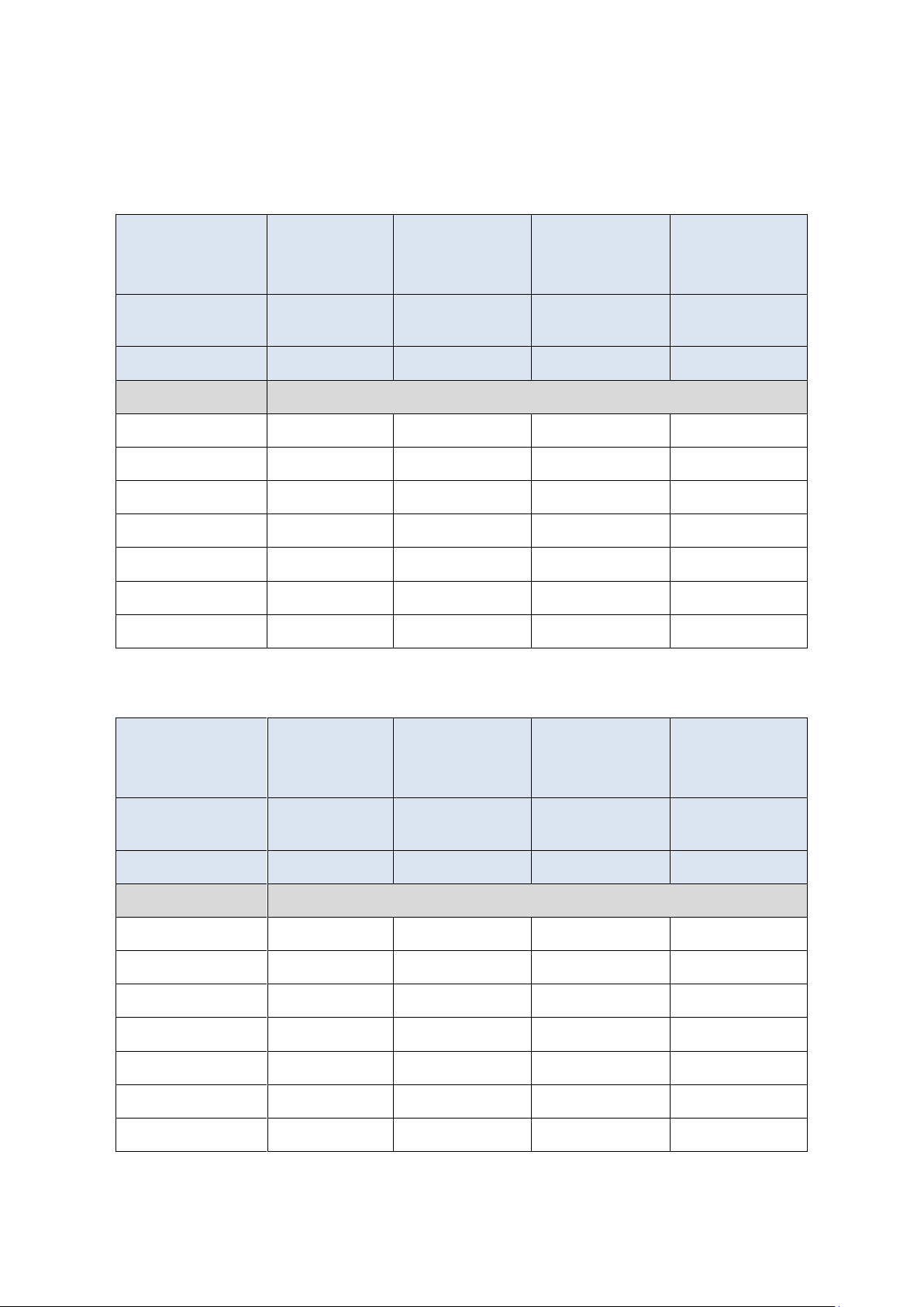
interface output (SD) in the tables below. If measuring frequency will be higher as the values in
the table some measured values will be lost. Please double check with a new setting of measuring frequency MF the BR setting.
Page 23
LAM71, Release 001_Revision 001
25
Binary output
Output values
Distance
Distance
+ signal quality
Distance
+ temperature
Distance
+ signal quality
+ temperature
Length of output data
(Byte)
2 3 3
4
Output data format
SD 2 0
SD 2 1
SD 2 2
SD 2 3
Baud rate
Maximum output frequency = MF max (Hz)
9600
470
300
300
220
19200
900
600
600
450
115200
5750
3800
3800
2880
230400
11600
7700
7700
5800
460800
23200
15500
15500
11600
921600
40000
30300
30300
23000
2000000
40000
40000
40000
34000
Decimal output
Output values
Distance
Distance
+ signal quality
Distance
+ temperature
Distance
+ signal quality
+ temperature
Length of output data
(Byte)
11
16
17
22
Output data format
SD 0 0
SD 0 1
SD 0 2
SD 0 3
Baud rate
Maximum output frequency = MF max (Hz)
9600
80
50
48
40
19200
160
100
90
75
115200
1000
700
660
480
230400
2000
1400
1300
980
460800
4100
2750
2500
1850
921600
7300
4750
4350
3300
2000000
12200
7850
6480
5000
Page 24
26
LAM71, Release 001_Revision 001
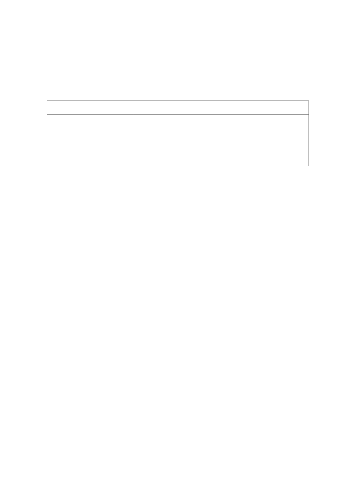
6.6.6 MW – Measurement window
This is for parameterising the range of a measurement window, starting with x and terminating with y.
Parameter z set the output value before and after the range of measurement window (MW).
Only those measured values are put out which are within the range of the measurement window.
For example, the measurement window can be used to:
- Blank out interfering objects before and behind a measurement range
- Determine a defined measurement range
An object detected before or behind the measurement window will generate the output of an invalid
measured value.
Query:
MW
Set:
MWx y z
Value range parameter x:
float32; resolution: 0.001 (= 1 mm)
Value range parameter y:
float32; resolution: 0.001 (= 1 mm)
Value range parameter z:
0 or 1
Standard:
-71.000 71.000 0
Output: MW -71.000 71.000 0
LAM71 does not perform a plausibility check of the preset measurement window. It is the responsibility of the user to set the correct parameters.
Output values:
Measuring window
distance < x
x < distance < y
distance > y
z = 0
DE02
Measuring value
DE02
z = 1
No output/ blanking pulse
Measuring value
No output/ blanking pulse
Page 25
LAM71, Release 001_Revision 001
27
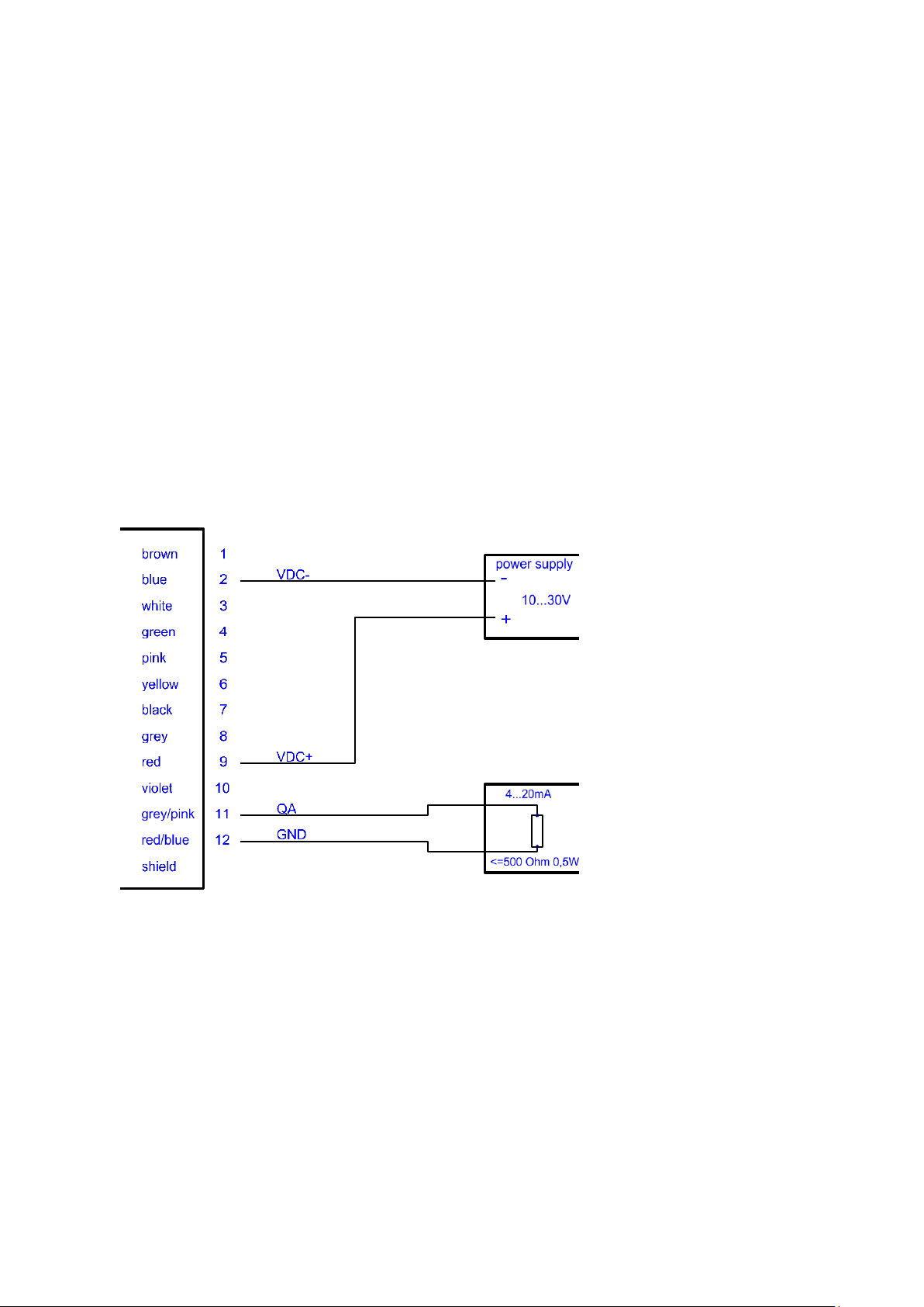
6.6.7 OF – Offset
OF parameterises a user-specific offset x which is added to the measured value.
Query:
OF
Set:
OFx
Value range parameter x:
float32; resolution: 0.001
(-250.000m … +250.000m; resolution 1mm = 0.001m)
Standard:
0.000
Output: OF 0.000
LAM71 does not perform a plausibility check of the preset offset. It is the responsibility of the user to
set the correct parameters.
Page 26
28
LAM71, Release 001_Revision 001
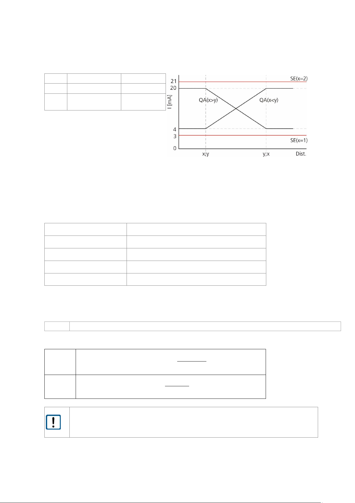
6.6.8 QA – Analogue output
The analogue output enables standardised analogue distance data transfer over long distances by
means of a two-wire line. The current of 4...20 mA impressed in the line is proportional to the measured distance within an adjustable distance interval. Parameterisation is done via the serial interface.
The current to be put out in case of faulty measurements is parameterised via the command SEx.
Analogue output properties:
- 4 mA ... 20 mA
- Indication in case of error: 3 mA or 21 mA (selectable via parameter SE) or last measured value
- Resolution: 16 bit digital-to-analogue converter
If current/voltage is to be converted, there must be a load resistor of < 500 Ohms/0.5 W (12 V of internal voltage --> max. measuring current of 0.024 A) between current output QA and GND.
Fig. 5 Wiring of analogue output QA
Page 27
LAM71, Release 001_Revision 001
29
Value
Description
Specification
x
Lower limit
x ≠ y
y
Upper limit
y ≠ x
Fig. 6 Analogue output
The lower limit value can be lower or higher than the upper limit value; the current range will invert accordingly.
Entries of identical limit values will be ignored and not be transferred.
Query:
QA
Set:
QAx y
Value range parameter x:
float32; resolution: 0.001
Value range parameter y:
float32; resolution: 0.001
Standard:
0.000 1.000
The LAM71 does not perform a plausibility check of the QA settings. It is the responsibility of the user
to set the correct parameters.
The measurement window MW (see 6.6.6) applies to the analogue output as well.
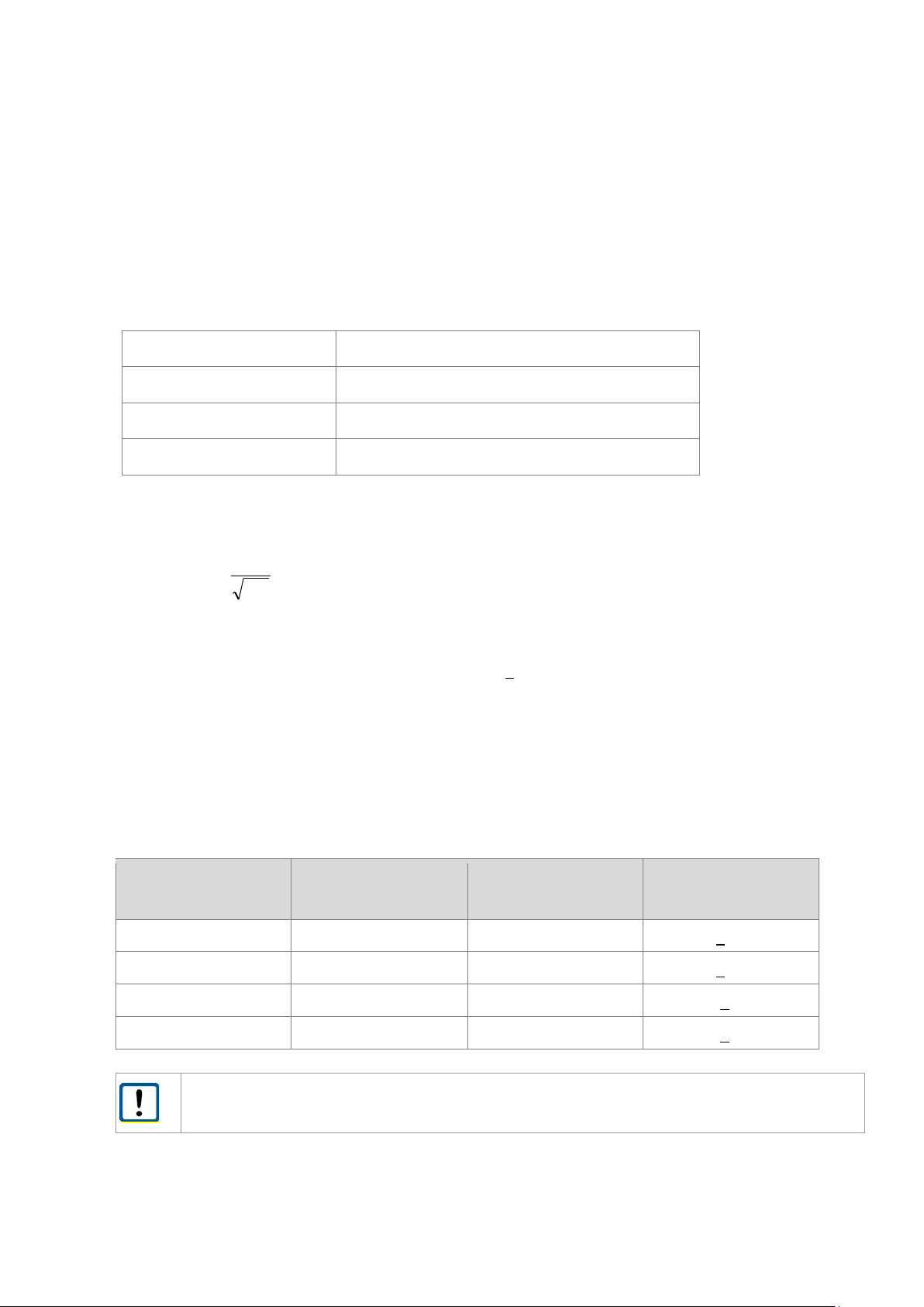
The output current (in mA) is calculated as follows:
x < y
•
xy
xDist
mAmAmAQA
−
−
+= *164][
x > y
•
yx
yDist
mAmAmAQA
−
−
−= *1620][
Dist = measuring distance
Please do not use the analog output for fast processes with high distance changes).
The typical settling time for a jump between 4 mA and 20 mA will be 40 µs .
Page 28
30
LAM71, Release 001_Revision 001
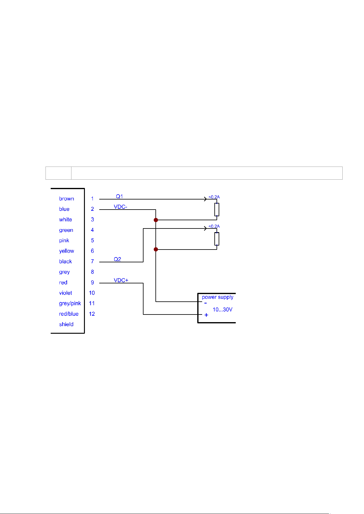
6.6.9 Q1/ Q2 – Switching output
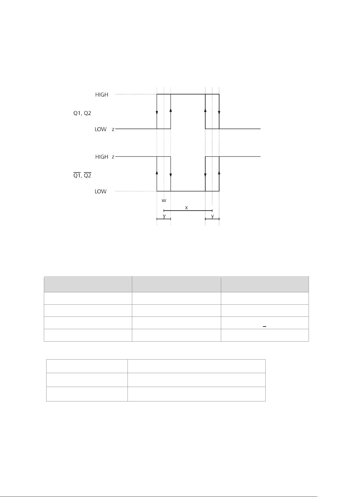
Switching outputs Q1 and Q2 show the distance information as logical switching information. They signalise whether the preset hysteresis switching range is exceeded or fallen short of.
Thus, they are ideally suitable for direct further processing of monitored values such as fill level or object detection. Parameterisation is done via the serial interface.
A load resistor of > 150 Ohms/ 6 W (max. operating voltage of 30 V; max. load current of 0.2 A) must be
switched against VDC- (GND of supply voltage) at the switching output. It is important that the load current of 0.2 A is not exceeded.
Typical resistance: 1 kOhm against VDC- (not against GND)!
Q1/Q2 parameterises the behaviour of the switching outputs.
The parameters include the beginning w of the measuring range when the output switches, the length x
of the measuring range, the hysteresis y as well as the logic behaviour z.
Figure 4 Wiring of switching outputs Q1 and Q2
Page 29
LAM71, Release 001_Revision 001
31
Low = 0 U < 1 V
High = 1 : U = operating voltage – 1V
Variable
Description
Specification
w
Switching threshold
- 9999,999 ... + 9999,999
x
Switching range
x > 0 ; x > y
y
Switching hysteresis
y > 0
z
Switching state
z = 0 or 1
Query:
Q1 or Q2
Set:
Q1w x y z or Q2w x y z
Standard:
0.000 1.000 0.050 1
The LDS30 does not perform a plausibility check of Q1 or Q2 settings respectively.
Figure 5 Switching behaviour of Q1 or Q2 respectively
Page 30
32
LAM71, Release 001_Revision 001
6.6.10 SA – Mean value average
SA parameterises the number x of the single measured values to be averaged for one measurement. SA
directly correlates with the measurement frequency MF.
SA and MF determine the output frequency of the measured values.
Query:
SA
Set:
SAx
Value range parameter x:
32 bit integer; resolution: 1
Standard:
1000
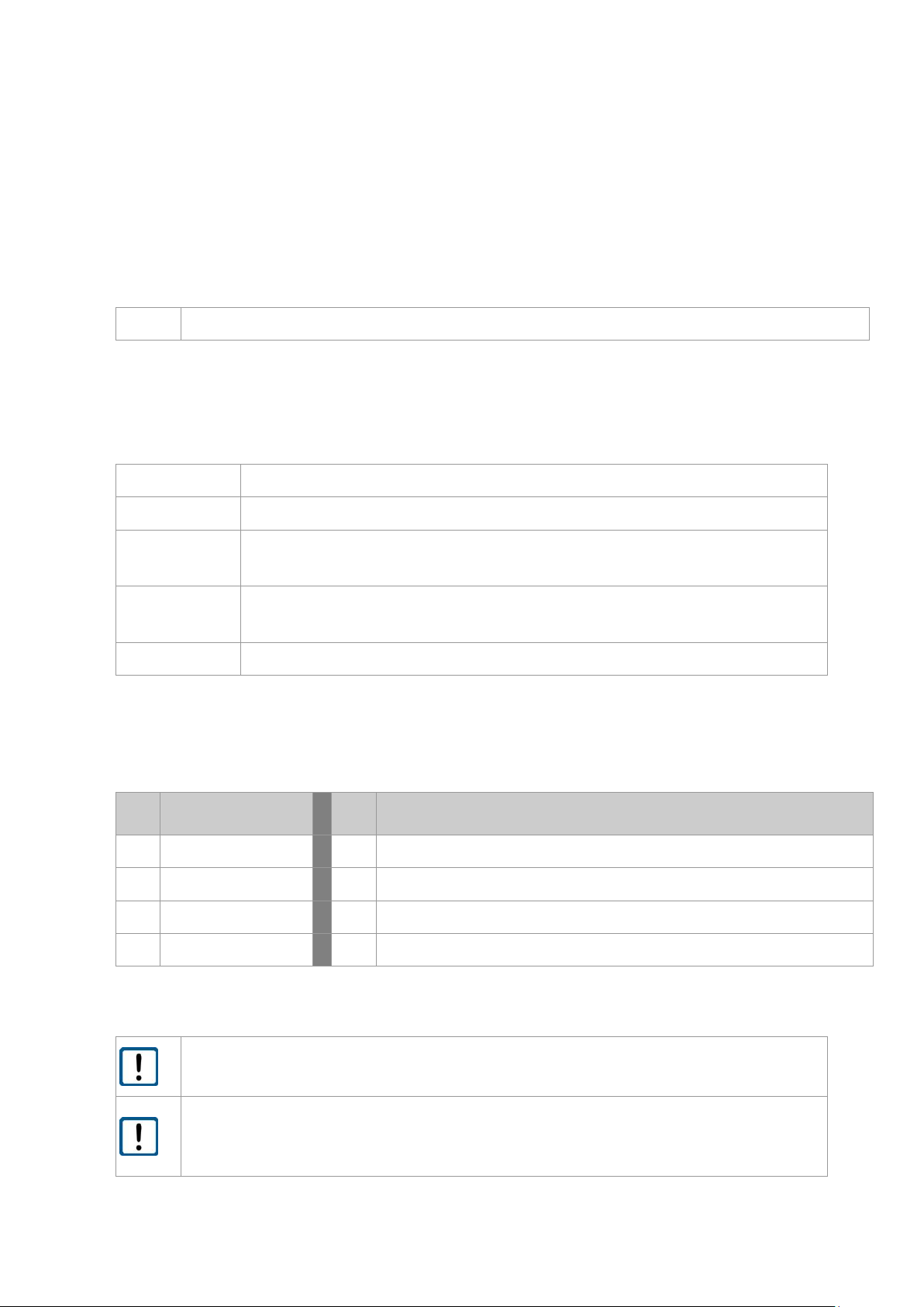
The dispersion of the measured values can be reduced by calculating the mean value.
SA
1
SA
=
σSA Dispersion after mean value determination from several distance
measurements
σ
1
Dispersion of single measured value (+ 60 mm)
SA
Mean value
Example:
For table below applies:
Measuring frequency 15 kHz and output frequency 15 kHz will be achieved with following parameters:
Baud rate 921.600 / binary output
Measurement
frequency MF (Hz)
Mean value SA
Output frequency (Hz)
Dispersion (mm)
15000
1
15000
+ 60
15000
10
1500
+ 19
15000
100
150
+ 6
15000
1000
15
+ 2
For SA will be used all valid measured distance values. If distance is out of the measurement window MW the measured value will ignored for the SA calculation.
Page 31
LAM71, Release 001_Revision 001
33
6.6.11 SO – Set offset
SO carries out a single distance measurement and sets it as - OF (offset). SO can only be executed and is
not really a parameter.
SO can be used for zero adjustment of distances in systems or processes.
Please note the interaction of parameter MW, OF, SO.
6.6.12 SD – Data format of serial interface output
SD parameterises the output format n and the output values m.
Query:
SD
Set:
SDn m
Value range
parameter n:
0, 1, 2
Value range parameter m:
0, 1, 2, 3
Standard:
0 0
Example:
Input: SD 0 3
Output: SD 0 3
n
Output format
m
Output values
0
Decimal
0 Distance
1
not available
1 Distance + signal quality (not available for binary)
2
Binary
2 Distance + temperature (not available for binary)
3 Distance + signal quality + temperature (not available for binary)
Output format 1 (hexadecimal) is not available!
For binary output distance value is available only (not temperature and/ or signal quality).
In conjunction with the baud rate, the output format determines the maximally possible
output speed of measured values. If a higher measurement frequency is set, the results of
some measurements will not be put out.
Page 32
LAM71, Release 001_Revision 001
35
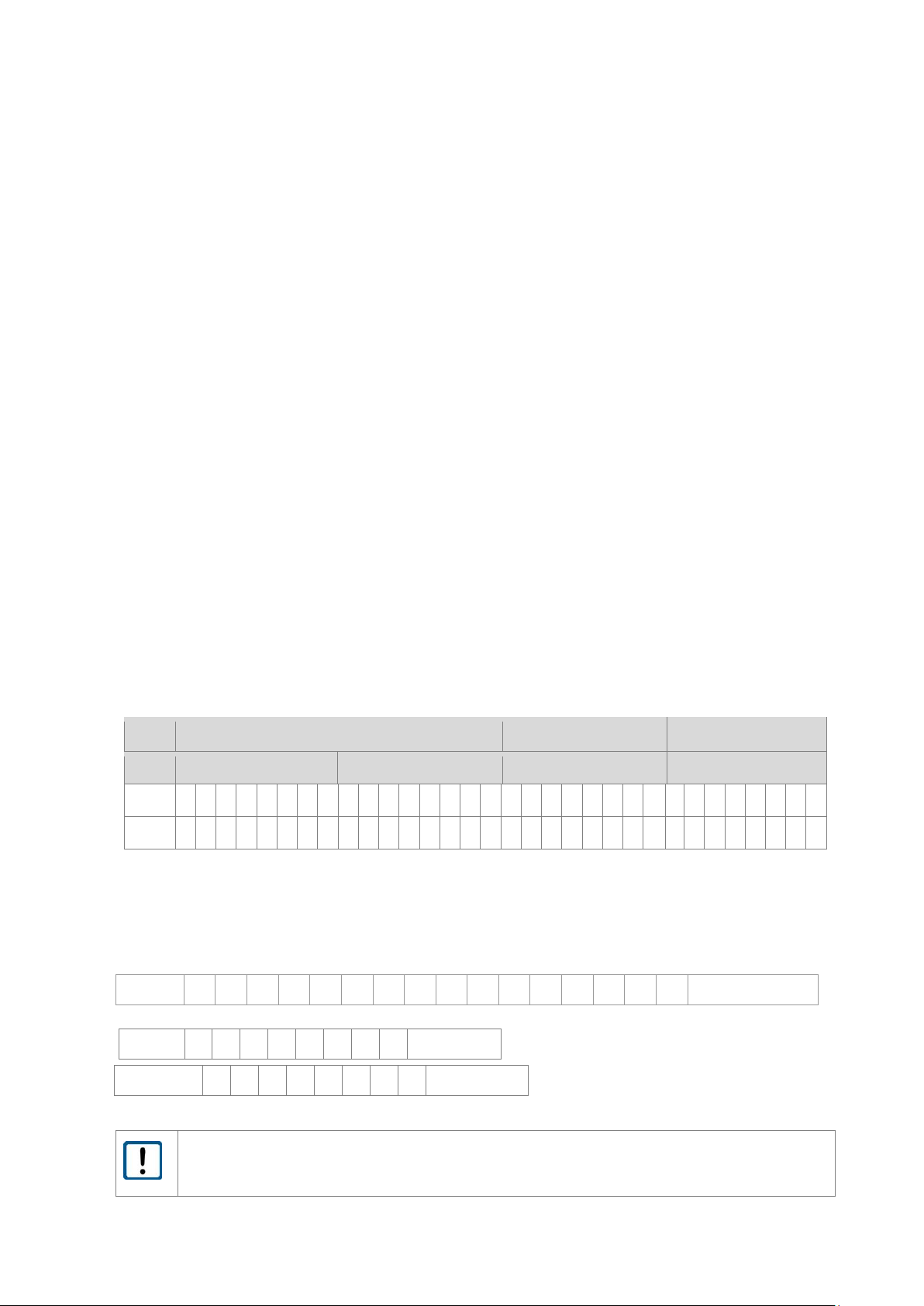
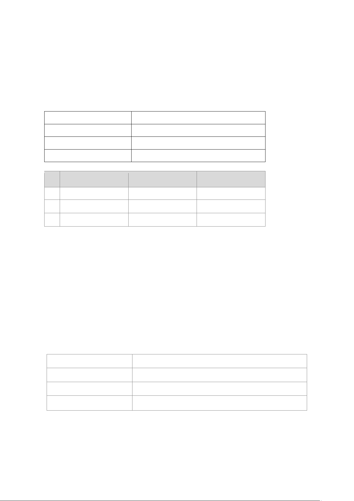
Binary format:
Distance:
2 bytes, MSB = bit 7
MSB of byte 1 is always 1.
MSB of byte 0 is always 0.
Data in each byte = bit 6 … bit 0
Coding: Two’s complement
Conversion of binary value into decimal value: *1/100
Signal:
1 byte
MSB = bit 7
MSB of byte 0 is always 0.
Data = bit 6 … bit 0
Temperature:
1 byte
MSB = bit 7
MSB of byte 1 and 0 is always 0.
Data in each byte = bit 6 … bit 0
Conversion of binary value into decimal value: -40
Distance
1 0 0 0 0 0 1 0 0 1 0 1 0 0 1 0 : 100 = 3.38 m
The binary distance range will determined by parameter UB.
If the distance value is below or above the distance range, the binary output is 0!
Distance (2 bytes)
Signal (1 byte)
Temperature (1 byte)
Byte 1
Byte 0
Byte 0
Byte 0
Bit
7 6 5 4 3 2 1 0 7 6 5 4 3 2 1 0 7 6 5 4 3 2 1 0 7 6 5 4 3 2 1
0
Data
1 x x x x x x x 0 x x x x x x x 0 x x x x x x x 0 x x x x x x
x
Signal
0 0 0 0 1 0 1 1 * 2 = 22
Temperature
0 1 0 1 1 1 0 1 - 40 = 53°C
Page 33
36
LAM71, Release 001_Revision 001
6.6.13 SE – Error mode
Parameterises the behaviour x of switching outputs Q1 and Q2 and of analogue output QA in case of
faulty measurements as well as the state after carrying out a single distance measurement.
Query:
SE
Set:
SEx
Value range parameter x:
0. 1 or 2
Standard:
1
x
Q1, Q2 (z=0)
Q1, Q2 (z=1)
QA
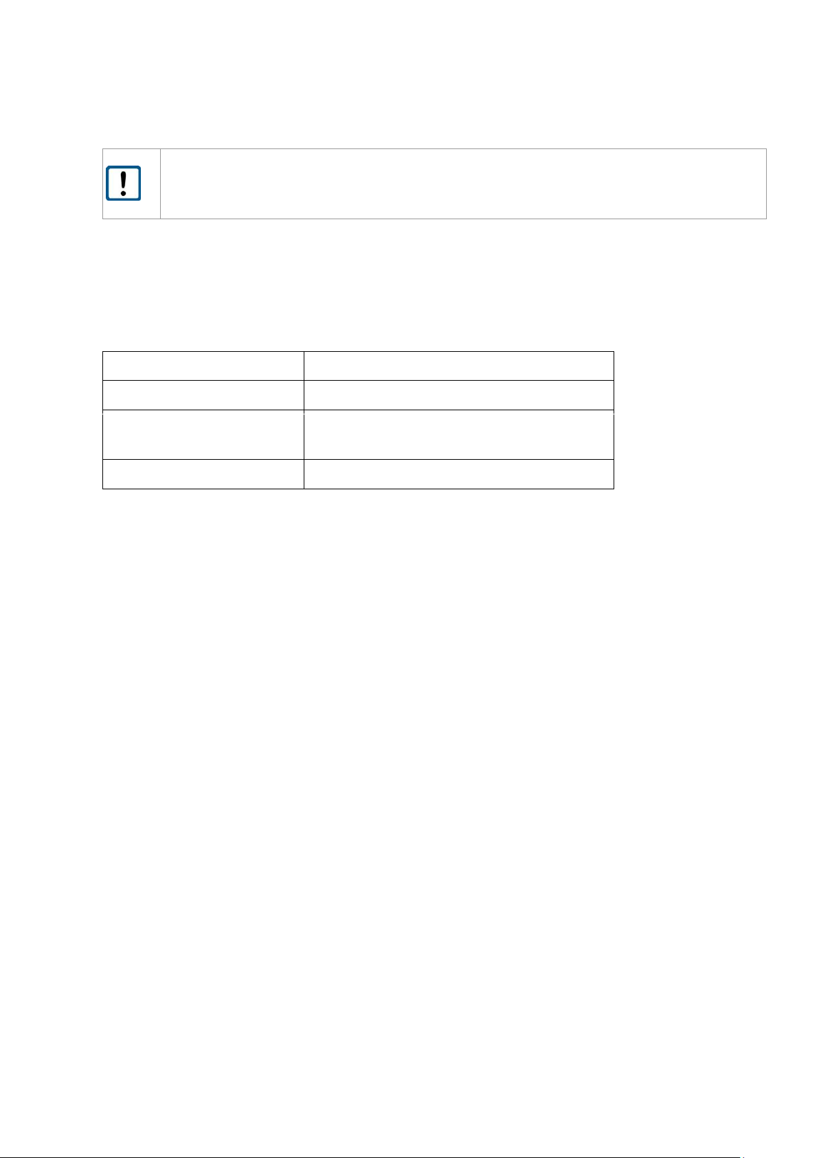
0
Last value
Last value
Last value
1
High
Low
3 mA
2
Low
High
21 mA
Low: U < 1 V
High: U = operating voltage – 1 V
The LAM71 does not perform a plausibility check of the preset error mode.
6.6.14 ST – Select Target
ST defines the target which should be detected. LAM71 is able to detect 4 different target in maximum.
Selection will be done between the first or the last detected target.
first target – target next to the LAM71
last target – last detected target
Output will be the distance of the defined target.
Query:
ST
Set:
STx
Value range parameter x:
0 (first target) or 1 (last target)
Standard:
0
Output: ST 0
Page 34
LAM71, Release 001_Revision 001
37
Parameter MW (measurement window) and SA (mean value, average) will influence the output.
If the selected target will be outside of the range of measurement window the output will be not
a distance values → please see setting of MW parameter z.
6.6.15 TC – Time Calibration
Parameterises the time between 2 customized calibrations.
The calibration is necessary to stabilize the distance accuracy and to avoid a lower accuracy because of
temperature changes in the environmental of the electronic parts.
Query:
TC
Set:
TCx
Value range parameter x:
0 (no calibration),1… 3660 (seconds)
(= 1 sec up to 1 h interval)
Standard:
1
Up to a Measuring frequency of approx. 35 kHz the calibration will be done without any influences of
the output frequency.
Between 35 k Hz and 40 kHz it could be possible that the data output will interrupt for one (1) distance
output every x seconds (x= parameter of TC).
Page 35
38
LAM71, Release 001_Revision 001
6.6.16 TE – Terminator
Sets the terminator for the output of measured values in ASCII format (see also command SD).
Query:
TE
Set:
TEnn
Value range parameter nn:
0 … 9
Standard:
0
Example:
Input: TE 1
Output: TE 1
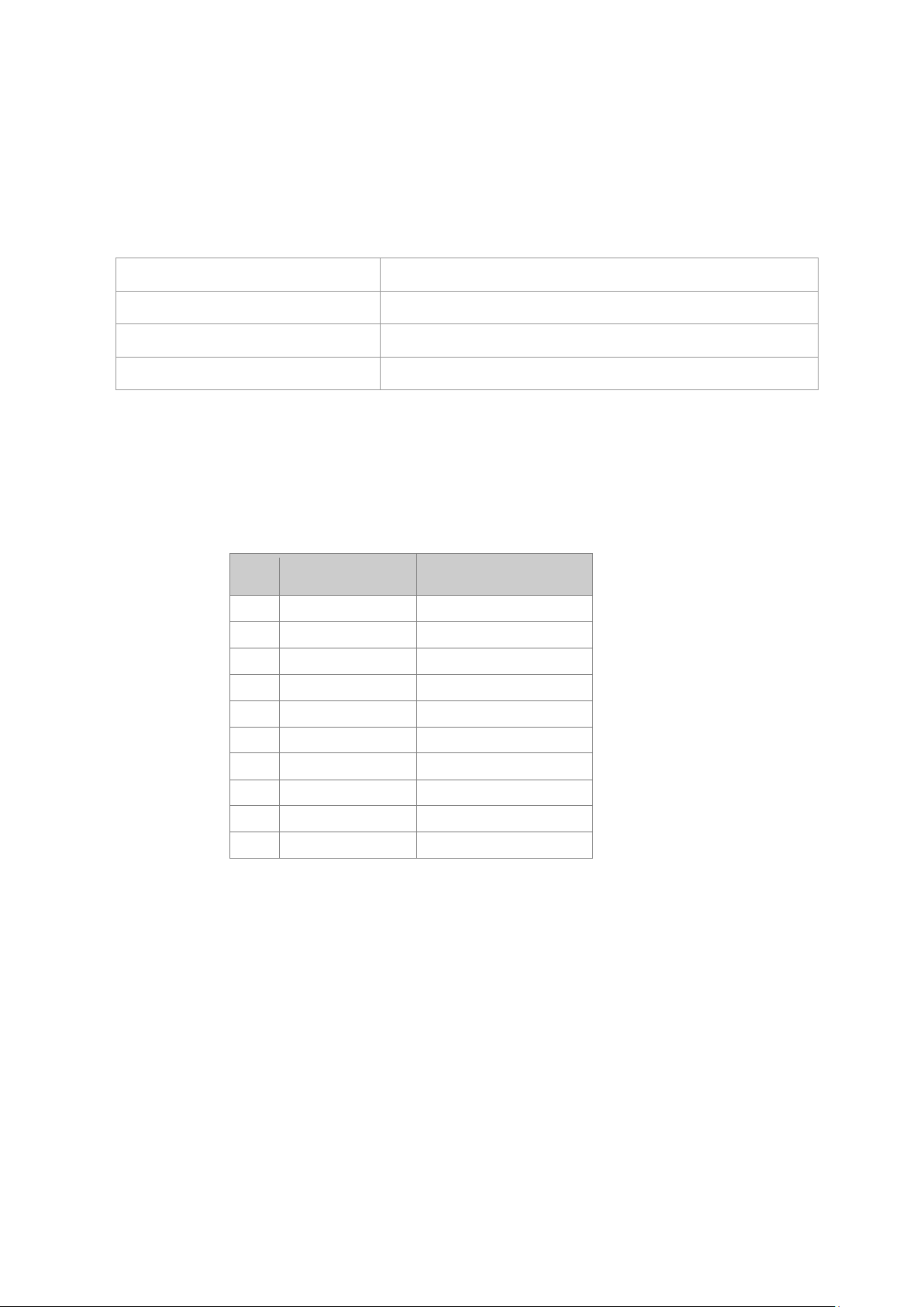
Possible values:
nn
ASCII
Meaning
0
0x0D 0x0A
CR LF 1 0x0D
CR 2 0x0A
LF 3 0x02
STX 4 0x03
ETX 5 0x09
HTab 6 0x20
Space 7 0x2C
Single quote
8
0x3A
Colon 9 0x3B
Semicolon
When an invalid character is entered, it will not be set. The previous terminator will be maintained.
Page 36
LAM71, Release 001_Revision 001
39
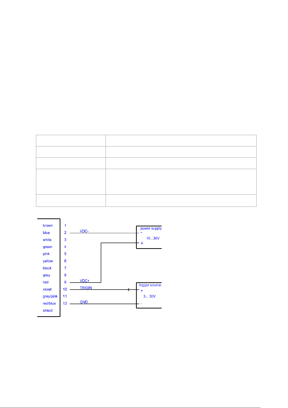
6.6.17 TI + TO Trigger
Trigger function
The LAM71 Trigger could be used as input or output.
1. Trigger input / external trigger function:
External trigger signal will be sent → start of measurement DM in accordance with parameter TI.
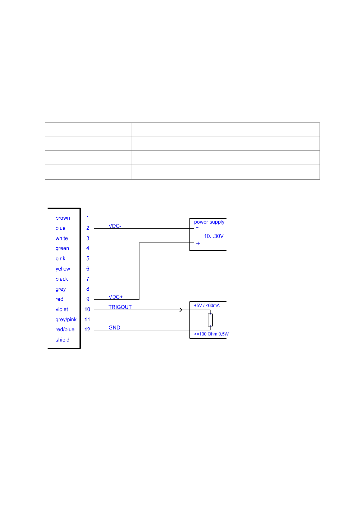
2. Trigger output / e.g. connection between 2 LAM71:
The output trigger signal of the 1. LAM71 (parameterized with TO) starts a single measurement DM
of the second LAM71 (parameterized with TO).
3. Continuous distance tracking controlled by trigger
Differences between trigger input and trigger output
Important is the parameter y of TI and TO.
TI y > 0 / TO y = 0 Trigger input
The measurement starts after an external trigger impulse.
TI y = 0 / TO y >0 Trigger output
LAM71 sends a trigger impulse to the second device.
The parametrization of the trigger connection is carried out via the serial interface or the internal display.
For the trigger function may only be activated TI or TO. A concurrent use of TI and TO is not
possible → output of warning information w1907
Voltage levels for the trigger signals
Low level
0 – 1.5 V
High level
3 – 30 V
Threshold
2.25 V
Hysteresis
0.1 V
Page 37
40
LAM71, Release 001_Revision 001
TI – Trigger input
The parametrization of trigger input will be set with command TI.
x edge parameterized the edge of trigger signal and
start and stop for “Autotrigger function”
0 rising edge (from LOW to HIGH)
1 falling edge (from HIGH to LOW)
2 every edge
3 start or stop of Autotrigger with rising edge
4 start or stop of Autotrigger with falling edge
y delay parameterized the time (delay) up to the measurement in milliseconds msec
Query:
TI
Set:
TI x y
Value range parameter x:
0, 1, 2, 3, 4
Value range parameter y:
0 to max 60 000 msec (equal to 1 minute)
active: from 1 msec upward
disabled: 0 msec
Standard:
0 0
Output: Trigger (input) [TI]: 0, 0
Maximum frequency of external trigger signal for Trigger IN (TI): 30 k Hz
If the trigger frequency is too high, no measurement value can be determined. The output is E02.
The trigger frequency must be reduced.
Figure 6 Wiring of trigger input
Page 38
LAM71, Release 001_Revision 001
41
TO – Trigger output
The parametrization of trigger output will be set with command TO.
x edge parameterized the edge of trigger signal
0 rising edge (from LOW to HIGH)
1 falling edge (from HIGH to LOW)
2 every edge
Query:
TO
Set:
TO x
Value range parameter x:
0, 1, 2
Standard:
0
Output: Trigger (output) [TO]: 0
Maximum frequency of Trigger OUT (TO) = MF (Measurement frequency)
Figure 7 Wiring of trigger output
Page 39

42
LAM71, Release 001_Revision 001
AUTOTRIGGER function_ Continuous distance tracking controlled by trigger
The parametrization of AUTOTRIGGER function will be set with command TI.
The first trigger signal starts the command which is defined in AUTOSTART (command AS) the second
trigger signal will stop the process.
x edge parameterized the edge of start or stop of Autotrigger signal
3 start or stop of Autotrigger with rising edge
4 start or stop of Autotrigger with falling edge
y delay parameterized the time (delay) up to the measurement in milliseconds msec
Query:
TI
Set:
TI x y
Value range parameter x:
3, 4
Value range parameter y:
0 to max 60 000 msec (equal to 1 minute)
active: from 1 msec upward
disabled: 0 msec
Standard:
0 0
Example:
AS DT
TI 3 10
First trigger signal starts a continuous measurement (DT) with the rising edge. The delay
between the triggersignal and start of measurement is 10 msec.
Next trigger signal stops a continuous measurement (DT) with the rising edge. The delay
between the triggersignal and stop of measurement is 10 msec.
Page 40
LAM71, Release 001_Revision 001
43
6.6.18 UB – Unit for binary output
UB parameterized the resolution (in bit) for distance values in binary format (in mm).
Query:
UB
Set:
UBx
Value range parameter x:
float32; resolution: 0.001
Standard:
1000.000
Example:
Input: UB 2.5
Output: UB 2.500
This parameter influences all measurement outputs in binary format independent of the measuring frequency.
The binary output format will be set with parameter SD.
Example:
UB 0.001 → resolution 1 µm
UB 1.000 → resolution 1 m
UB 1000.000 → resolution 1 mm (standard)
The measuring range will be depicted with 14 signed bits.
Distance value (binary) = Distance (mm) / UB
Distance range (binary) : -8192 < Distance < 8191
If the distance value is below or above the distance range, the binary output is 0!
Page 41

44
LAM71, Release 001_Revision 001
7 Serial interface and communication software
Transmittion protocol
• Interface settings: Asynchronous, 8 data bits, no parity, 1 stop bit
• Transmission protocol format / syntax: 7 bit ASCII
• Proprietary transmission protocol
• Commands are case-insensitive (NO differentiation between lower and upper case).
• Decimal separator in the output of figures is the dot “.” (0x2E).
• The terminator of a command (sending command) is ENTER (0x0D, 0x0A) or Carriage Return
(0x0D) or Line Feed (0x0A)
• Where parameters have several values, they are separated by a space (0x20).
• The response to commands with parameters is the respective command including the parame-
ters.
• The response to commands without parameters is the respective command including the cur-
rent parameters.
• The response to commands with parameters outside of the valid value range is the respective
command including the current parameters.
• The response to unknown commands and faulty parameter formats is a “?” (0x3F).
Page 42
LAM71, Release 001_Revision 001
45
8 Error processing
In case of one or more detected errors, the error code with the highest index will be outputted (most
serious defect/ error).
Example:
no distance value identified, no other error: DE02
no distance value identified, in addition temperature out of range: DE06
Non-critical errors will be reset automatically, a critical error requires a device reset (see table) –
command DR or power off/ on. Hardware errors generate error code DE04.
Error code
Description
Reset
DE02
no distance identified
Automatically, with the next measuring
value
DE04
Device error ( hardware )
Not automatic, device reset necessary
DE06
Temperature out of range
Automatically, if measured temperature
is in the specified range
DE10
Internal laser voltage lower than the defined
minimum voltage (ULaser
MIN
)
Not automatic, device reset necessary
In binary format all errors will be sent as “0” (00).
The described error codes will be outputted, if an error is detected during
- LAM71 measurement (DM, DT)
- a measuring mode (DM, DT) will be started.
Output of error message (like output of measuring values):
- once for measuring mode DM
- in the specified output frequency for measuring mode DT
The measuring mode DT could be stopped with <ESC> in the case of error and error message output
too. The communication with LAM71, e.g. parameterizing, reset or start of new measurement, will be
not influence by the error message. If DT is started and the error did not reset automatically, the error
message will be outputted again.
The temperature (check with command TP) may be higher than the ambient temperature. Approx. 30 min after power ON the measured temperature could be 25 Kelvin
higher than ambient temperature.
Page 43
46
LAM71, Release 001_Revision 001
9 Technical Data
Following table shows the specified target values. For all devices which will be delivered before the series approval the specified parameters are not proven and no guarantee is given.
Measurement properties
Measurement principle
Time of flight (TOF)
Measured parameter
Distances
Measuring range 1
Total range
Typical range on target board 1, 2
Typical range on natural surface, 80% reflectivity 1
Typical range on natural surface, 10% reflectivity 1
0.2 m to 270 m
0.2 m … 270 m
0.2 m … 125 m
0.2 m … 70 m
Accuracy, absolute
1 3
+ 60 mm (1 )
Repeatability 4
+ 25 mm (1 )
Resolution of measured values
1 mm
Measurement frequency, maximum
40 kHz
Laser
Laser classification
Laser class 1, EN 60825-1:2014
Wavelength
905 nm (invisible)
Divergence, transmitter
2 mrad x 0.4 mrad
Electric connection conditions
Supply voltage
10 V DC … 30 V DC
Power consumption
< 3 W
Interface/ connections
Connections on device
12 pole jack M12 (Binder 713 series) 09-3491-970-12
Environmental and application conditions
Operating temperature
-40 °C … +60 °C
Storage temperature
-40 °C … +70 °C
Humidity
15 % … 90 %, non-condensing
Housing protection class
IP 67
Dimensions
98 mm x 46 mm x 25 mm (L x W x H) inclusive connector
Weight
approx. 137 g
1
dependent on target reflectivity, stray light, measurement frequency and environmental conditions in addition to distance and operation mode
2
Measuring range for special targets, e.g. Scotchlite Cube
3
Accuracy can be ± 100 mm for close-up ranges up to 1 m.
4
Repeatability ± 50 mm at measurement distance 70 m.
Page 44

Sensor Partners
Sensor Partners BV – Head office
James Wattlaan 15
5151 DP Drunen
The Netherlands
 Loading...