

Page 1
1
LZR®- U905
LASER MEASUREMENT DEVICE
EN
User’s Guide for product version 0300 and more
Page 2
2
1
2
3
4
5
6
7
9
8
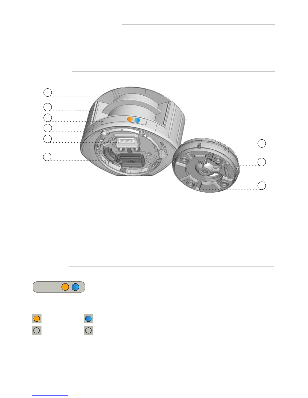
DESCRIPTION
1. laser sweep emission
2. laser sweep reception
3. LED-signal (2)
4. screw for position lock (2)
5. connector
6. protection cover
7. notch for tilt angle adjustment (2)
8. adjustable bracket
9. cable conduit (4)
LED-SIGNAL
ERROR LED POWER LED
no error
error
no power
power
Other use of the device is outside the permitted purpose and can not be guaranteed by the manufacturer.
The manufacturer cannot be held responsible for incorrect installations or inappropriate adjustments of the sensor.
LASER MEASUREMENT DEVICE
Page 3
3
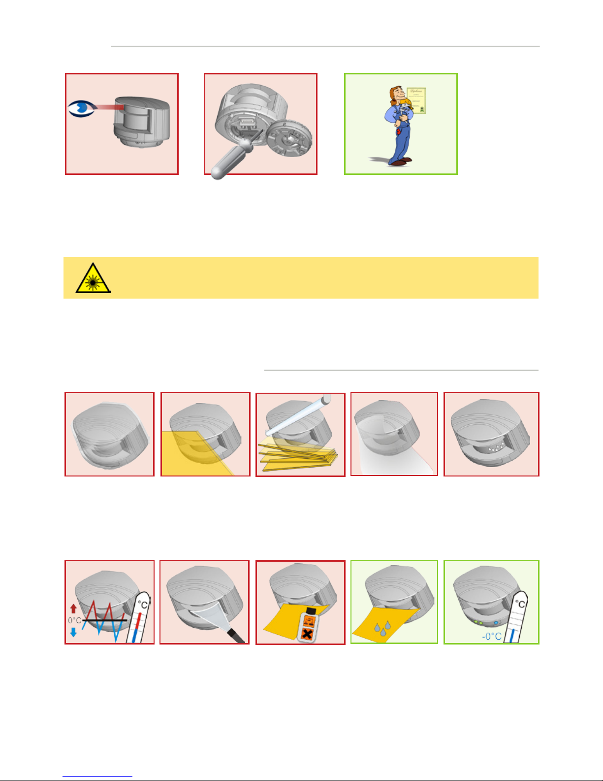
SAFETY
Do not look into the laser
emitter.
The warranty is void if
unauthorized repairs are
made or attempted by
unauthorized personnel.
Only trained and qualified
personnel may install and
adjust the sensor.
INSTALLATION AND MAINTENANCE
Avoid extreme
vibrations.
Do not cover
the front screens.
Avoid moving objects
and light sources in
the detection field.
Avoid condensation.
Avoid the presence
of smoke and fog in
the detection field.
Avoid exposure to
sudden and extreme
temperature changes.
Keep the sensor
permanently powered
in environments where
the temperature can
descend below 0°C.
Wipe the front
screens regularly
with a clean and
damp cloth.
Do not use aggressive
products to clean
the front screens.
Avoid direct exposure
to high pressure
cleaning.
CAUTION!
Use of controls, adjustments or performance of procedures other than those specified herein
may result in hazardous radiation exposure.
Page 4
4
1
5
6
7 8
1 2
3
4
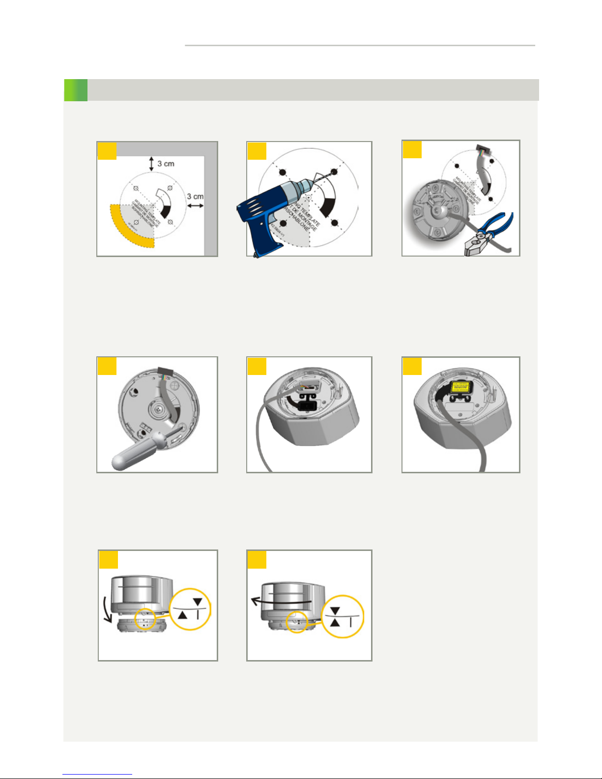
MOUNTING
Use the adhesive mounting
template to position the
sensor correctly. The grey
area indicates the detection
range.
Drill 4 holes as indicated
on the mounting template.
Make a hole for the cable if
possible.
Pass the cable +/- 10 cm
though the cable opening.
If drilling an opening is
not possible, use the cable
conduits on the back side of
the bracket.
Position the bracket and
fasten the 4 screws firmly.
Open the protection cover,
plug the connector and
position the cable in the slit.
Close the protection cover
and fasten it firmly.
Turn the sensor until the two
triangles are face to face.
Position the housing on
the bracket.
INSTALLATION STEPS
Page 5
5
2
1
2
3
3
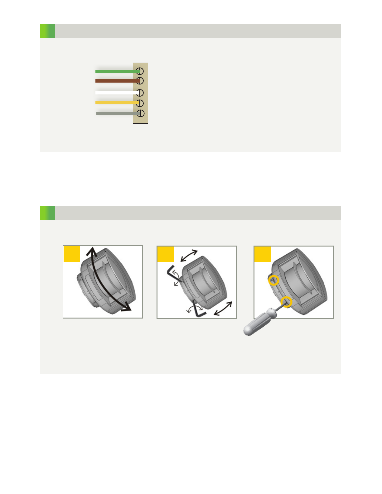
GND
RS485B
RS485A
+ 24 V DC
GND PWR
GREEN
BROWN
WHITE
YELLOW
GREY
WIRING
Adjust the lateral position of
the detection field.
Adjust the tilt angle of the
detection field with the hex
key.
Lock the position of the
mounting bracket to avoid
malfunctioning in case of
extreme vibrations.
POSITIONING
Page 6
6
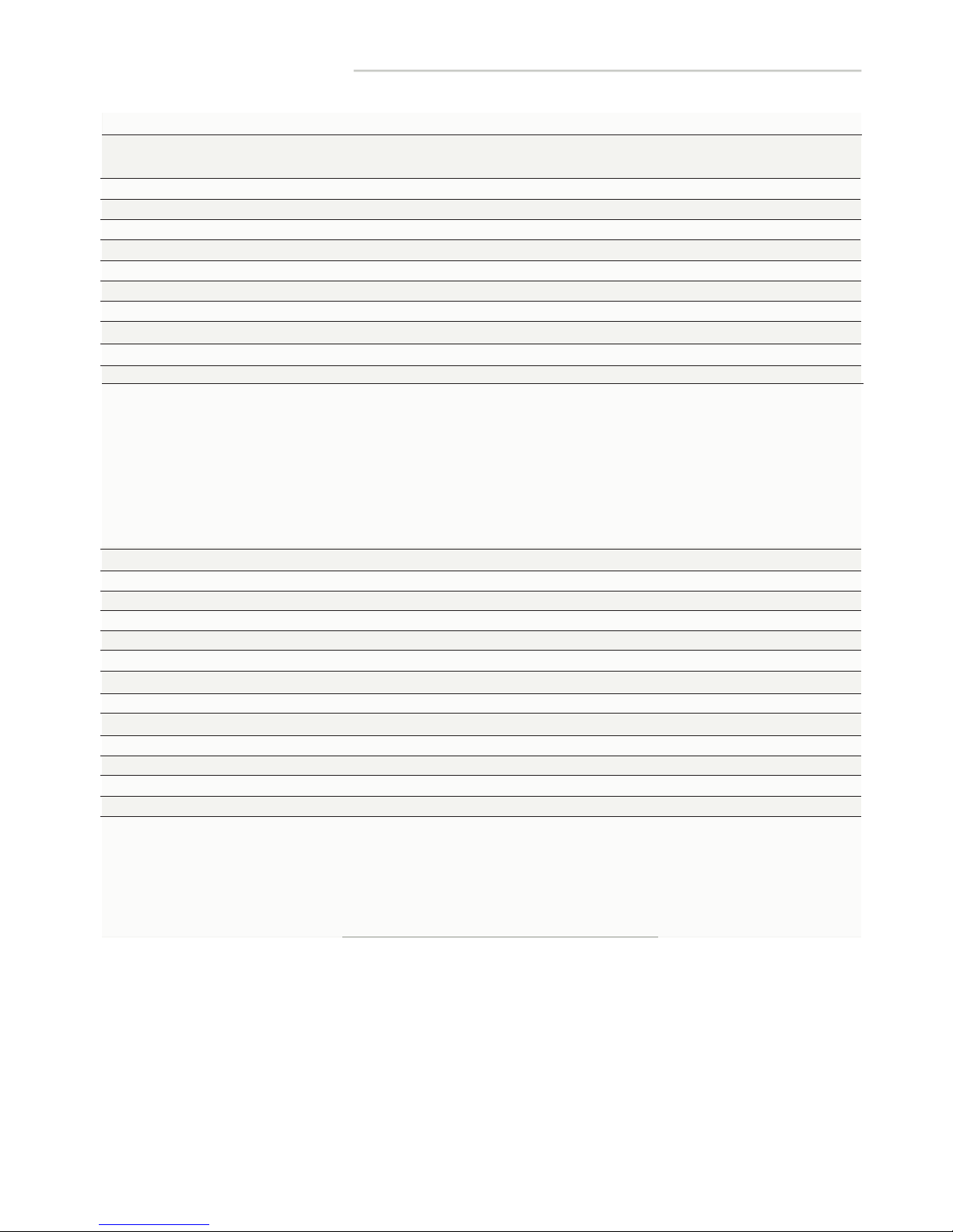
Technology:
Measurement range:
Number of planes:
Number of points/plane:
Angular resolution:
Angular coverage:
Rotating speed:
Remission factor:
Laser emission characteristics:
Supply voltage:
Power consumption:
Peak current at power-on:
Serial communication:
Type
Interface
Communication mode
Transmission speed
Topology
Symbol coding
File type
LED-signal:
Dimensions:
Material:
Colour:
Mounting angles on bracket:
Rotation angles on bracket:
Tilt angles on bracket:
Protection degree:
Temperature range:
Humidity:
Vibrations:
Pollution on front screens:
Expected lifetime:
Norm conformity:
laser scanner, time-of-flight measurement
max 65 m
9 m @ 2% remission factor
4
274
0.3516 °
96.3281 °
900 turns/min
> 2 %
wavelength 905 nm; max. output pulse power 75 W (CLASS 1)
10-35 V DC @ sensor side
< 5 W
1.8 A (max. 80 ms @ 35 V)
see application note LZR®-90X Protocol (available for download on our website)
asynchronous
RS 485
half-duplex
460800 bit/sec
point to point
1 start bit, 1stop bit, no parity bit
8 bits
1 blue LED: power-on status; 1 orange LED: error status
125 mm (D) x 93 mm (W) x 70 mm (H) (mounting bracket + 14 mm)
PC/ASA
black
-45 °, 0 °, 45 °
-5 ° to +5 ° (lockable)
-3 ° to +3 °
IP65
-30 °C to +60 °C if powered; -10 °C to +60 °C unpowered
0-95 % non-condensing
< 2 G
max. 30 %; homogenous
8 years
2006/95/EC: LVD; 2002/95/EC: RoHS; 2004/108/EC: EMC
EN 50155:2007; EN 60529:2001;
IEC 60825-1:2007 Laser Class 1; EN 60950-1:2005
EN 61000-6-2:2005 EMC - Industrial level
EN 61000-6-3:2006 EMC - Commercial level
TECHNICAL SPECIFICATIONS
Specifications are subject to changes without prior notice.
All values measured in specific conditions.
Page 7
7
1
1
1
1
1
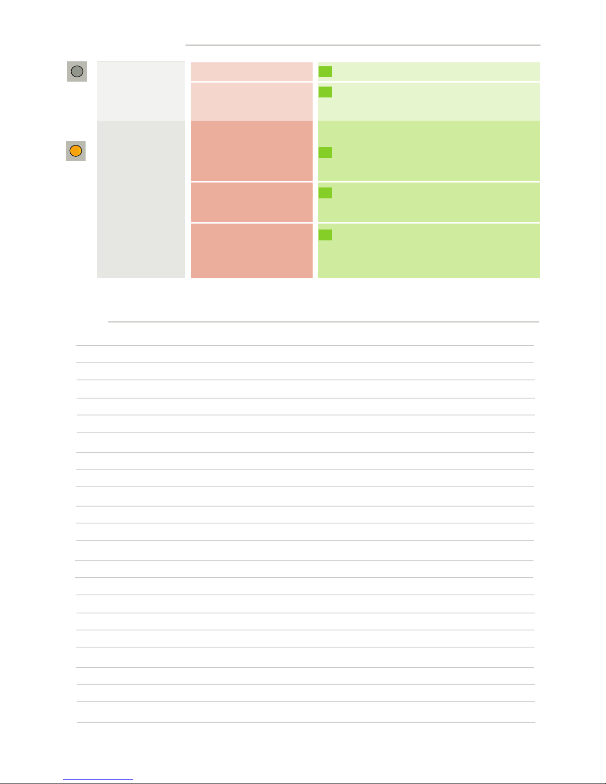
TROUBLESHOOTING
No blue LED
The orange LED
is on.
There is no power.
The power supply voltage
is exceeding the acceptable
limits.
The sensor exceeds its
temperature limits.
Internal error
The polarity of the power
supply is inverted.
Check cable and connexion.
Check the power supply voltage.
Verify the outside temperature where the sensor
is installed. Eventually protect the sensor from
sunlight using a cover.
Wait a few seconds.
If the LED remains ON, reset the power supply.
If the LED turns on again, replace the sensor.
Check the polarity of the power supply.
NOTES
Page 8
8
A DIVISION OF BEA SA | LIEGE SCIENCE PARK | ALLÉE DES NOISETIERS 5 - 4031 ANGLEUR [BELGIUM]
T +32 4 361 65 89 | F +32 4 361 28 58 | [email protected] | WWW.SENSORIO.BE
BEA hereby declares that the LZR®-U905 is in conformity with the basic requirements and the other relevant
provisions of the directives 2006/95/EC, 2002/95/EC and 2004/108/EC.
Angleur, April 2012 Jean-Pierre Valkenberg, authorized representative
The complete declaration of conformity is available on our website: www.sensorio.be
EC countries: according to the directive 2002/96/EC for Waste Electrical and Electronic Equipment (WEEE)
©BEA | ORIGINAL INSTRUCTIONS | 42.7652 / V1 - 04.12
PLEASE KEEP FOR FURTHER USE
DESIGNED FOR COLOUR PRINTING
 Loading...