


1
2
3
4
3
1/8
LZR -S600
®
1. Relay 1 - Field 1
2. Relay 2 - Field 2
3. Error
4. Power
GREEN LED
RED LED
BLUE LED
ORANGE LED
LED
FLASHES
QUICKLY
LED
FLASHES
NORMALLY
LED
FLASHES
SLOWLY
LED
OFF
DETECTION
POWER ON
ERROR
NO
DETECTION
Adjustable bracket
Cable conduit
LED-signal
Visible
laser beams
Laser sweep
reception
Laser sweep
emission
Tilt angle
adjustments
Main connector
Front screens
Caution! Exposure
to laser radiation.
Factory values
See the indicated page
for further information
LASER SCANNER FOR
OBJECT AND BUILDING SECURITY *
LED-SIGNAL
USED SYMBOLS
DESCRIPTION
USER’S GUIDE
*Other use of the device is outside the permitted purpose and can not be guaranteed by the manufacturer.

CLASS 1 LASER PRODUCT
CAUTION! CLASS 3R
LASER RADIATION
ACCESSIBLE DURING
INSTALLATION.
1
2
3
4
°C
-0°C
Ex.
F1
F2
?
x2
1
2
3
4
5
6
7
8
0
9
EFA-SCAN
®
=
=
=
=
0°C
°C
2/8
LZR -S600
®
Do not stare into
the laser emitter.
Do not stare into
the visible red laser
beams.
Do not open the
sensor. Warranty is
void if opened.
The sensor should
only be installed
and adjusted by
authorized and
trained staff.
After installation
enter an access
code to secure the
sensor.
Caution! Use of controls,
adjustments or performance of
procedures other than those
specified herein may result in
hazardous radiation exposure.
The device contains IR and visible red laser diodes.
IR laser (CLASS 1): wavelength 905nm
max. output pulse power 75W
Red laser (CLASS 3R): wavelength 650nm
max. output CW power 3mW
Fasten the sensor
firmly to avoid
vibrations.
If the sensor is used in
environments where
the temperature can
descend below
0°C, keep the sensor
permanently powered.
Avoid exposing the
sensor to sudden and
extreme temperature
changes.
Smoke and fog may
cause unwanted
detections.
Do not cover
the front screens.
Avoid moving objects
in the detection field.
Avoid all types of light
sources in the
detection field.
Wipe the front screens
regularly with a clean
and damp cloth.
Do not use aggressive
detergents or abrasive
cleaning agents to
clean the front screens.
Avoid condensation.
SAFETY INSTRUCTIONS
INSTALLATION TIPS
2/8

4
1
8
5
6
2
7
3
9
MOUNTING
TEMPLA
TE
GABARIT
DE MONTAGE
BOHRSCHABLONE
42.5004-V1
MOUNTING
TEMPLA
TE
GABARIT
DE MONT
AGE
BOHRSCHABLONE
MOUNTING TEMPLA
TE
GABARIT
DE MONTAGE
BOHRSCHABLONE
42.5004-V1
42.5004-V1
MOUNTING
TEMPLATE
GABARIT
DE MONTAGE
BOHRSCHABLONE
42.5004-V1
MOUNTING
TEMPLA
TE
GABARIT DE MONTAGE
BOHRSCHABLONE
42.5004-V1
3/8
LZR -S600
®
Make a hole for the cable
if possible.
Drill 4 holes as indicated on the
mounting template.
Use the adhesive mounting
template to position the sensor
correctly. The grey area
indicates the detection range.
Position the housing on the
bracket.
Turn the sensor until the
two triangles are face to face.
Position the bracket and
fasten the 4 screws firmly in
order to avoid vibrations.
Plug the connector and
position the cable in the slit.
Close the protection sheath
and fasten it firmly.
MOUNTING
Pass the cable at least 8-10 cm
though the cable opening.
If drilling an opening is not
possible, use the cable conduits
on the back side of the bracket.
Power supply +
3/8
+
-
Monitoring
Monitoring
Power supply -
WHITE/BLUE
YELLOW
WHITE
GREEN
PINK
VIOLET
RED
BROWN
WHITE/RED
BLUE
Field 2
Field 1
RELAY 1
RELAY 1
RELAY 2
RELAY 2
No monitoring*:
polarity free connection to power supply
WIRING
* for more info, please contact BEA

REMOTE CONTROL
1
2
3
4/8
LZR -S600
®
Mounting side
1 LEFT with background
2 RIGHT with background
3 LEFT without background
4 RIGHT without background
5 MIDDLE without background
CORRECT POSITIONING
Adjust the tilt angle of the
sensor.
Adjust the lateral position.
Activate the visible laser beams if
you need a visual aid.
Lock the position of the
bracket to avoid
malfunctioning.
To unlock, use a screwdriver.
The beams will stay activated
for 15 minutes or can be
turned off the same way.
MOUNTING SIDE
Select the corresponding mounting side with background.
Make sure you stay at a distance to avoid disturbances.
By choosing a value with background, the sensor is
protected against misuse. The sensor memorizes the
reference to the floor and will signal a fault in case the
orientation of the sensor is changed.
The sensor learns its environment and automatically
determines its detection field(s).
Both RED LEDs flash and the 3 red laser beams
automatically light up during 30 seconds.
4/8
ANTI-VANDALISM
FIELD 1
FIELD 1
FIELD 2
FIELD 2
Field 1 can be configured as desired.
Field 1 can be configured as desired.
Field 2 can be configured as desired.
Field 2 should reach the background
to ensure anti-vandalism.
Mounting side
Mounting side

REMOTE CONTROL
00
05-99
00
05-99
05-99
99
99
99
99
00
05-99
5/8
LZR -S600
®
9.9 m
9.9 m
9.9 m
for a field height of 4 m
for a field height of 4 m
No field 2
0.5 m - 9.9 m
No field 1
0.5 m - 9.9 m
9.9 m
0.5 m - 9.9 m
Field 1 = Field 2
0.5 m - 9.9 m
for a field width of 3.5 m
for a field width of 3.5 m
Field height
Field width
REMOTE CONTROL
FIELD DIMENSIONS
TEACH-IN
Field height*
Field width
FIELD 2
FIELD 1
3 sec.
RED
RED
RED
RED
Before teach-in, you have 3
seconds to step out of the
detection field.
30 sec.
TEACH-IN
Wait for the sensor to learn its
environment.
During the teach-in, the sensor learns the new reference distances to all
objects within its detection zone.
deletes its memory and
Before you launch a teach-in, the selected field size must be bigger than the desired field size.
* if mounting side is set
to 1 or 2, the field height
should be the same as
the distance to the
background
5/8

REMOTE CONTROL
1
2
3
4
5
6
7
8
9
C1 C2 C3 C4
0 5 cm
1 10 cm
2 15 cm
3 20 cm
4 25 cm
6/8
LZR -S600
®
*approximate values, not guaranteed*approximate values, not guaranteed
Number of curtains*
REMOTE CONTROL
OTHER ADJUSTMENTS
Relay configuration
1 Indoor
2 Outdoor LOW
3 Outdoor MEDIUM
4 Outdoor HIGH
0 size filter deactivated
1 > 5 cm
2 > 10 cm
3 > 15 cm
4 > 20 cm
1 Active - NO
2 Passive - NC
3 Passive - NC
4 Active - NO
Passive - NC
Active - NO
Passive - NC
Active - NO
RELAY 1
RELAY 2
Immunity filter
Object size*
Uncovered zone
Relay redirection
0 field 1
1 field 1 or field 2
field 2
field 2
RELAY 1
RELAY 2
*only for field 2, field 1 = 4 curtains
6/8
7/8
LZR -S600
®
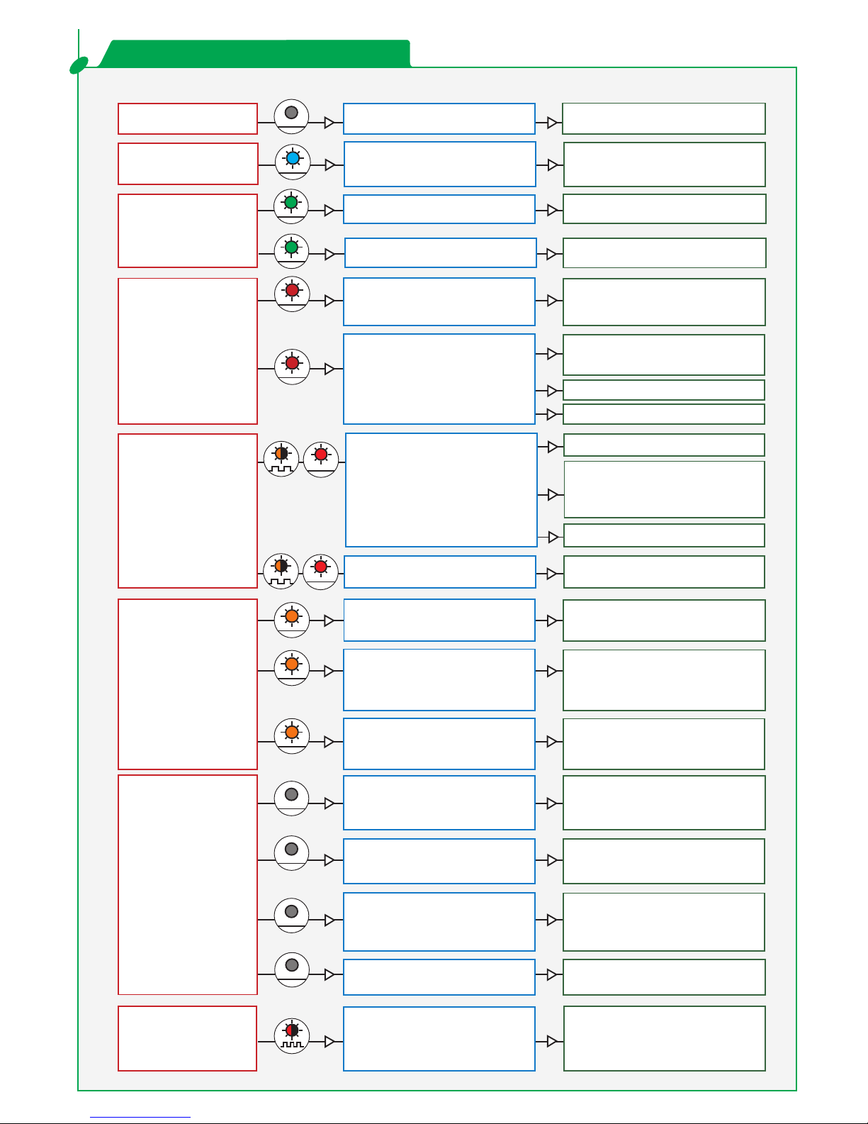
Execute a teach-in.
RED
RED
RED
GREEN
GREEN
RED
ORANGE
ORANGE
ORANGE
ORANGE
ORANGE
BLUE
RED
BLUE
NO LED
NO LED
NO LED
NO LED
Verify or replace the batteries.
Verify the outside temperature where
the sensor is installed. Eventually
protect the sensor from sunlight using
a cover.
Check the power supply voltage.
Wait a few seconds. If the LED remains
ON, reset the power supply. If the LED
turns on again, replace the sensor.
Check wiring.
The RED and BLUE cable have to be
connected to the monitoring input.
Point the remote control towards the
sensor, but with a slight angle. The RC
should not be pointed in a right angle in
front of the sensor.
Cut and restore power supply. No code
is required to unlock during the first
minute after powering.
Check cable and connexion.
Modify object size.
Check the size of the fields.
Walk out of the field and/or remove the
object(s) from the field.
Activate the 3 red beams and check if
the position of the sensor is correct. If
not, adjust the hex screws.
Cut and restore power supply. The
remote control session is accessible
again during 30 minutes.
Verify and clean the front screens.
Avoid highly reflective material in
proximity to the sensor.
Verify the field size.
Check the position of the sensor.
Launch a new teach-in.
Check mounting side setting.
If there is no background,
set the mounting side to value 3 to 5.
The sensor does not
respond to the remote
control.
The detection field LED
remains GREEN.
The detection field LED
remains RED.
Orange LED is flashing
and the detection field
LEDs are red.
Orange LED is ON.
Only the BLUE LED is
ON.
The batteries in the remote control
are not installed properly or dead.
30 minutes after last use of the
remote control, the sensor locks the
access to the remote control
session.
The remote control is badly pointed.
The sensor does not
unlock, even after
entering the access code.
You have to enter a code or the
wrong code was entered. (Maybe it
was changed?).
No blue LED
There is no power.
The detection field is too small.
The object size is too small.
You or any other object moves or
stays in the field.
The field is touching the floor, the
wall or the door, which leads to
detection.
The sensor is masked.
The sensor exceeds its temperature
limits.
The power supply voltage is
exceeding the acceptable limits.
Internal error
The monitoring input is not
connected.
LED
SYMPTOMS
POSSIBLE CAUSES
CORRECTIVE ACTION
TROUBLESHOOTING
A reflective object is in close
proximity to the sensor.
No background (reference point) is
found.
7/8

SENSORIO A division of BEA SA - LIEGE Science Park - Allée des Noisetiers 5 - 4031 Angleur [B] - T +32 4 361 65 89 - F +32 4 361 28 58 - info@sensorio.be - www.sensorio.be
LZR -S600
®
TECHNICAL SPECIFICATIONS
Technology:
Detection mode:
Max. detection range:
Remission factor:
Size of target:
Emission characteristics:
IR laser
Red visible laser
Supply voltage:
Power consumption:
Peak current at power-on:
Cable length:
Response time:
Output:
Max. switching voltage:
Max. switching current:
Switching time:
Output resistance:
Voltage drop on output:
Leakage current:
Input:
Response time monitoring input:
LED-signal:
Dimensions:
Material:
Colour:
Mounting angles on bracket:
Rotation angles on bracket:
Tilt angles on bracket:
Protection degree:
Temperature range:
Humidity:
Vibrations:
Pollution on front screens:
Expected lifetime:
Norm conformity:
Max. contact voltage:
Voltage threshold:
laser scanner, time-of-flight measurement
presence (EN 12453 Typ. E)
9.9 m x m
> 2 %
> 300 mm x 200 mm x 700 mm @ 10 m (EN 12445 testbody A)
Wavelength 905 nm; max. output pulse power 75 W
wavelength 650 nm; max. output CW power 3 mW
10-35 V DC @ sensor terminal
< 5 W
1.8 A (max. 80 ms @ 35 V)
10 m
typ 20 ms; max. 80 ms
2 electronic relays (galvanic isolated - polarity free)
35 V DC / 24 V AC
80 mA (resistive)
t =5 ms; t =5 ms
ON OFF
typ 30 Ù
< 0.7 V @ 20 mA
< 10 µA
1 blue LED: power-on status
1 orange LED: error status
2 bi-coloured LEDs: detection/output status (green LED: no detection; red LED: detection)
125 mm (D) x 93 mm (W) x 70 mm (H) (mounting bracket + 14 mm)
PC/ASA
black
-45 °, 0 °, 45 °
-5 ° to +5 ° (lockable)
-3 ° to +3 °
IP65 (avoid direct exposure to high pressure cleaning)
-30 °C to +60 °C if powered
-10 °C to +60 °C unpowered
0-95 % non-condensing
< 2 G
max. 30 %; homogenous
designed for a lifetime of min. 5 years
9.9
2 optocouplers (galvanic isolated - polarity free)
30 V DC (over-voltage protected)
Log. H: >8 V DC
Log. L: <3 V DC
< 5 ms
2006/95/EC: LVD; 2004/108/EEC: EMC; 2006/42/EC: MD
2002/95/EC: RoHS; EN 60825-1; EN 60950-1; EN 60529; IEC60825;
EN 61000-6-1: EMC - Commercial Level; EN 61000-6-2: EMC - Industrial level;
EN 61508 SILCL1
EN ISO 13849-1:2008 Performance Level «c» CAT 2
Specifications are subject to change without prior notice.
©BEA
42.7269 -V1 / 03.10
/
Original instructions /
Yves Borlez, Authorized representativeLiege, March 2010
The complete declaration of conformity is available on our website: www.bea.be
BEA hereby declares that the LZR -S600 is in conformity with the basic requirements and the other
relevant provisions of the standards 2004/108/EEC and 2006/42/EC.
®
 Loading...