

Page 1

Document No. 05648-01 Rev A4
EnRoute500
Installation Guide
Rev. A4
Internetworking the Physical World™
Sensoria Corporation
15950 Bernardo Center Drive, Suite J, San Diego, CA 92127
www.sensoria.com
technical support email: [email protected]
Page 2

EnRoute500 Installation Guide
Sensoria, the Sensoria logo and EnRoute500 are trademarks of Sensoria Corporation. All rights reserved.
All other company, brand, and product names are referenced for identification purposes only and may be trademarks that are
the properties of their respective owners.
Copyright © 2005-2006, Sensoria Corporation.
05648-01 Rev. A4
2
Page 3
EnRoute500 Installation Guide
FCC Notice to Users and Operators
This device complies with Part 15 of the FCC Rules. Operation is subject to the following two
conditions: (1) This device may not cause harmful interference, and (2) This device must
accept any interference received, including interference that may cause undesired operation.
This equipment has been tested and found to comply with the limits for Class B Digital Device,
pursuant to Part 15 of the FCC Rules. These limits are designed to provide reasonable
protection against harmful interference in a residential installation. This equipment generates
and can radiate radio frequency energy and, if not installed and used in accordance with the
instructions, may cause harmful interference to radio communications. However, there is no
guarantee that interference will not occur in a particular installation. If this equipment does
cause harmful interference to radio or television reception, which can be determined by turning
the equipment off and on, the user is encouraged to try to correct the interference by one or
more of the following measures.
• Reorient or relocate the receiving antenna
• Increase the separation between the equipment and receiver
• Connect the equipment into an outlet on a circuit different from that to which the receiver is
connected
• Consult the dealer or an experienced radio/TV technician for help
Any changes or modification to said product not expressly approved by Sensoria
Corporation could void the user's authority to operate this device.
The Sensoria EnRoute500 Mesh Router must be installed by a trained professional,
value added reseller, or systems integrator who is familiar with RF cell planning
issues and the regulatory limits defined by the FCC for RF exposure, specifically
those limits outlined in sections 1.1307.
05648-01 Rev. A4
3
Page 4
EnRoute500 Installation Guide
EnRoute500 Interfaces
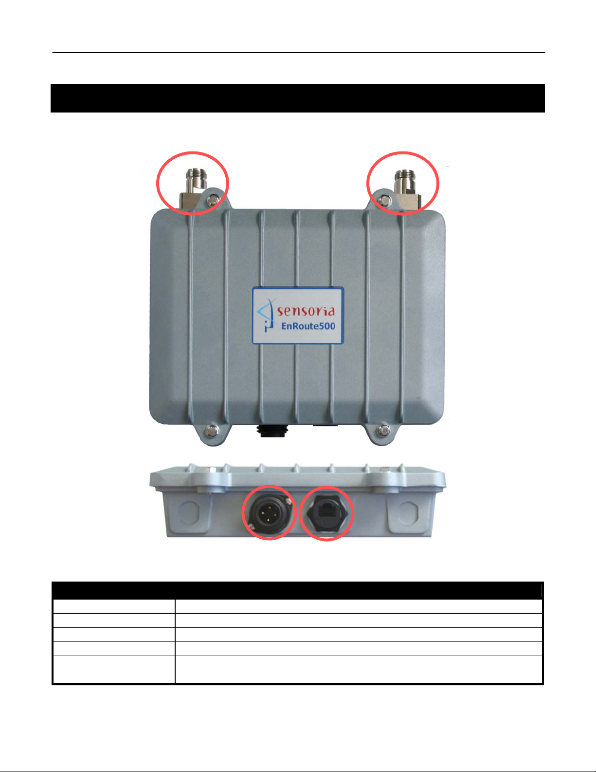
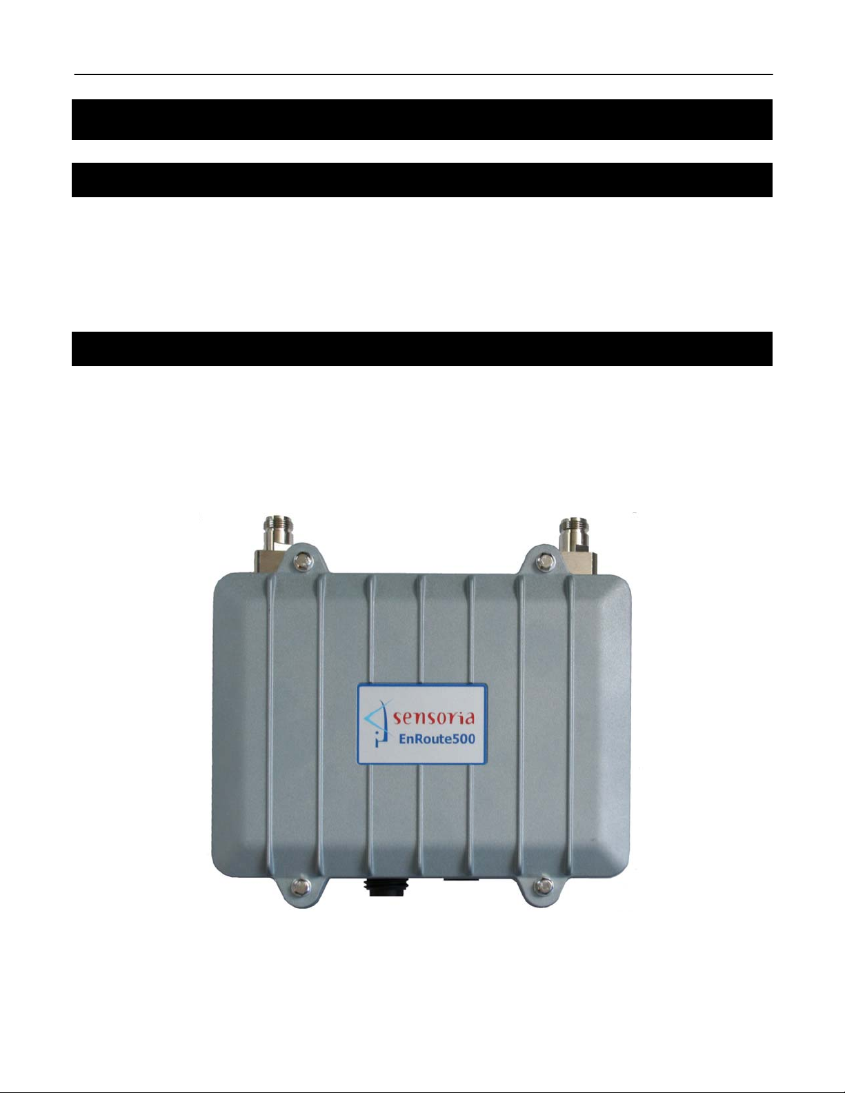
The interfaces available on the EnRoute500 are power, Ethernet and 2 radio antenna ports.
Mesh radio
port
AP radio
port
Power Ethernet
Figure 1. EnRoute500 interfaces
Interface Description
Power (100-240VAC) Main Power input
Radio 1 5.8GHz mesh radio antenna connector
Radio 2 2.4GHz access point antenna connector
Ethernet 10/100 Mbit Ethernet interface
Ethernet (POE) Secondary power input (9-28VDC)
Use supplied equipment only. Not compatible with IEEE 802.3af
05648-01 Rev. A4
4
Page 5
EnRoute500 Installation Guide
Installation Equipment
Mounting kits that cater to different applications are available for the EnRoute 500.
E500 Mounting and power kit, wall SNMNTPW-W
E500 Mounting and power kit, small vertical pole SNMNTPW-V
E500 Street lamp power and mounting kit, horizontal pole SNMNTPW-H
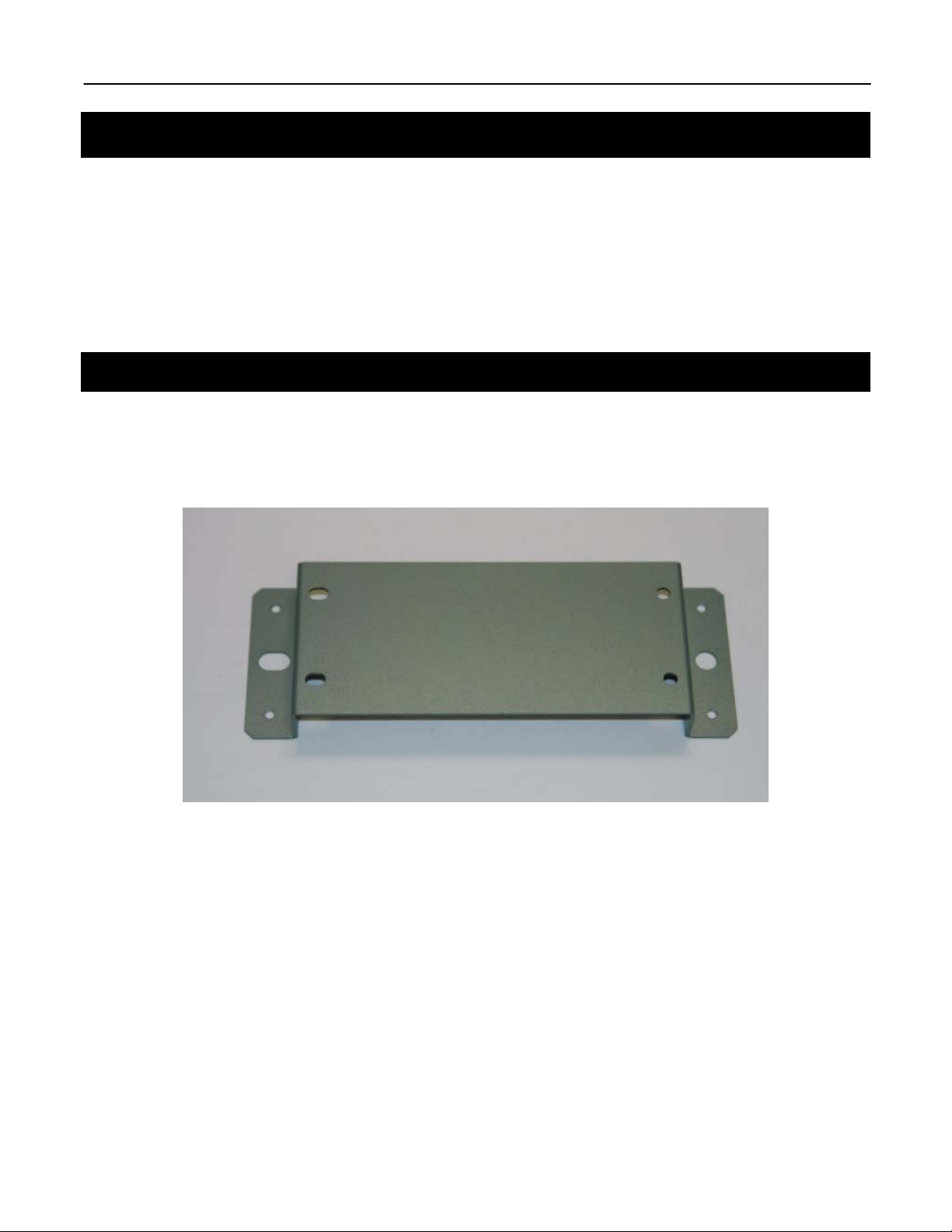
Wall Mounting (SNMNTPW-W)
• Mount to wood structures, with 1/4 " lag bolts
• Mount to masonry with masonry anchors
05648-01 Rev. A4
Figure 2. Wall mount bracket
5
Page 6
EnRoute500 Installation Guide
Vertical Pole Mounting (SNMNTPW-V)
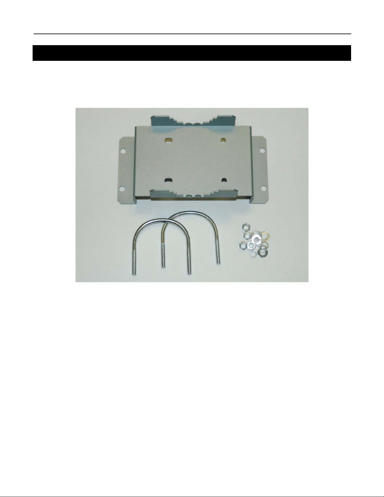
The EnRoute500 can be mounted to any vertical pole up to 1.5” using the SNMNTPW-V
Vertical Pole Mount Kit. The kit includes a mounting bracket, U-bolts and the ancillary
hardware necessary to affix the bracket to the enclosure.
Figure 3. Pole Mount bracket installation kit
05648-01 Rev. A4
6
Page 7
EnRoute500 Installation Guide
Streetlight Horizontal Pole Mounting (SNMNTPW-H)
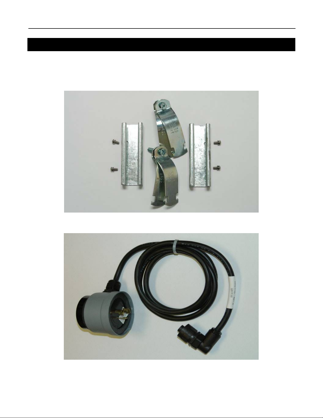
The Horizontal Pole Mounting kit includes two channel bracket mounting rails, two 2” pipe
support straps, four Allen screws and lock washers. It also includes a streetlight power tap
adapter used for supply power to the EnRoute500.
Figure 4. Streetlight horizontal pole mounting bracket kit
05648-01 Rev. A4
Figure 5. Streetlight power tap adapter
7
Page 8
EnRoute500 Installation Guide
Channel Brackets and Pipe Straps
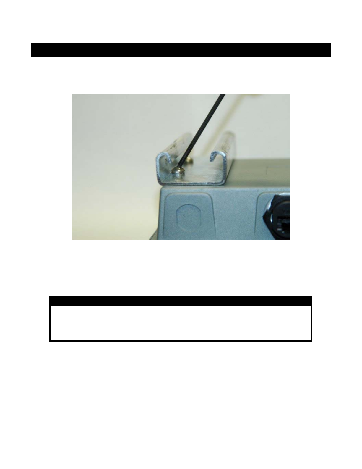
Attach the two channel brackets to the EnRoute enclosure with Allan screws and lock washers.
A ball-head Allan driver will need to be used to affix the screws. See Figure 6.
Figure 6. Channel bracket positioning
The EnRoute500 can be affixed to poles up 1.5” to 2” using the supplies pipe straps. Poles
with diameters larger than 2” up to 4” can be accommodated with the corresponding straps.
See Table 1.
Description Part Number
E500 Mounting accessory, pole strap, 2.5” SNMNTPW-2.5
E500 Mounting accessory, pole strap, 3.0” SNMNTPW-3.0
E500 Mounting accessory, pole strap, 3.5” SNMNTPW-3.5
E500 Mounting accessory, pole strap, 4.0” SNMNTPW-4.0
Table 1. Horizontal pole mounting accessories
05648-01 Rev. A4
8
Page 9
EnRoute500 Installation Guide
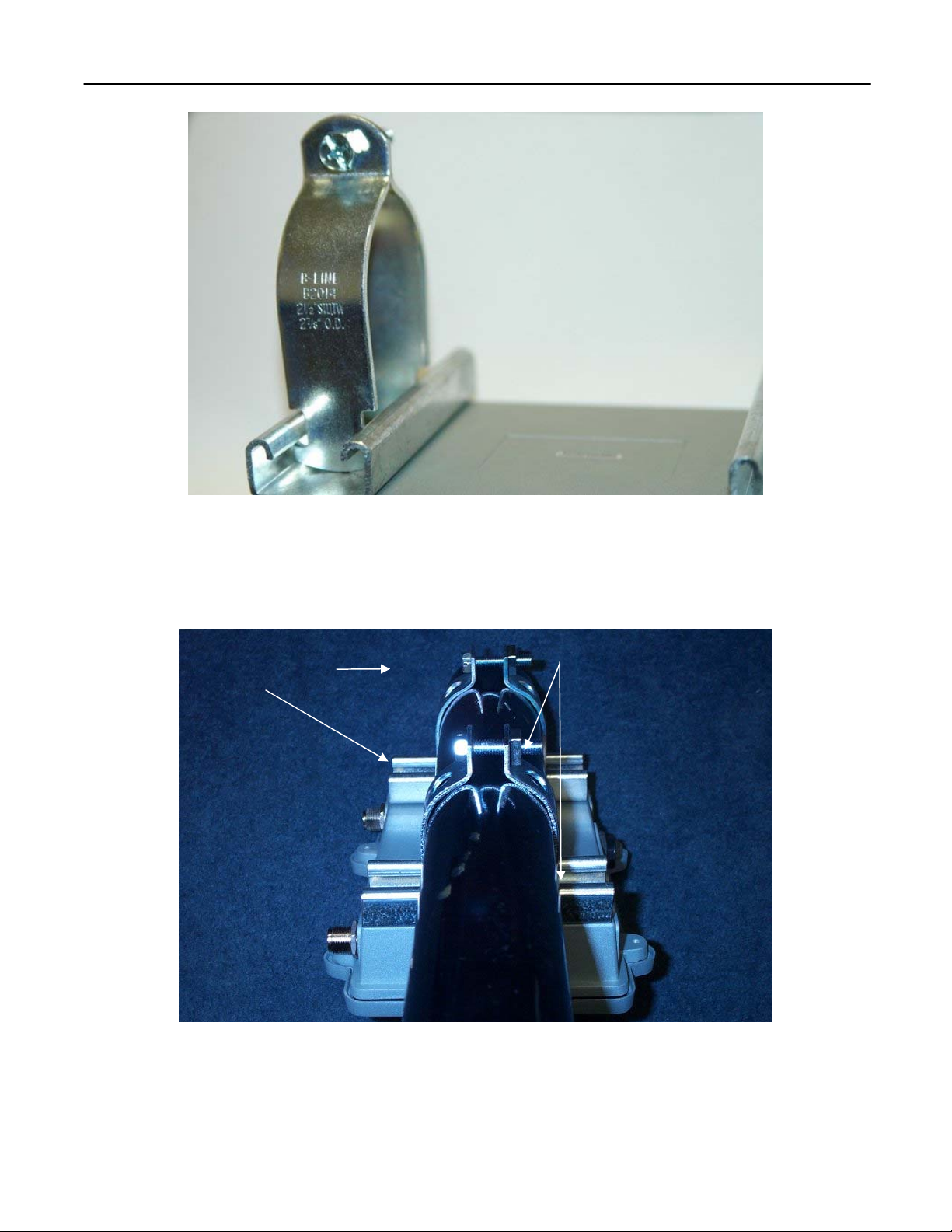
Figure 7. Channel bracket pipe strap
Secure pipe straps to the pole as shown in Figure 7. Pipe strap screws should be tightened
with enough force to prevent the enclosure from rotating.
Channel Brackets
Pipe Straps
05648-01 Rev. A4
Figure 8. Pole Mount bracket installation kit
9
Page 10
EnRoute500 Installation Guide
Power Connections
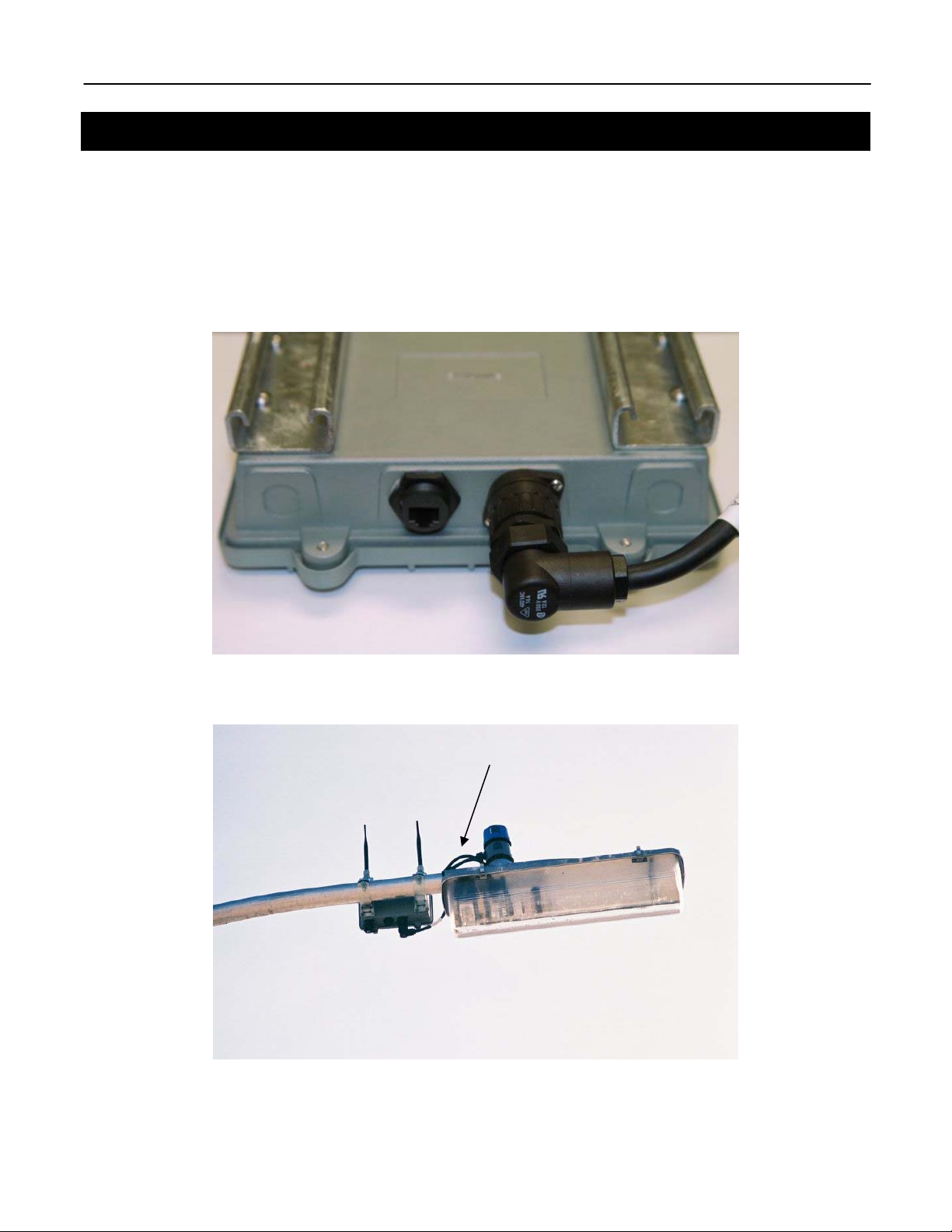
The streetlight power tap adapter should be installed before the cable is connected to the
EnRoute500. Remove the existing light sensor by twisting and pulling up. Once disengaged,
insert the power tap adapter in the socket and twist to lock. Re-install the light sensor in the
socket on top of the power adapter. Plug the opposite end of the power adapter cable into the
EnRoute500. Secure any excess cabling with wire ties. If the Ethernet port is not being used,
install the weather proof dust cap.
Figure 9. EnRoute500 power connection
Power Tap Adapter
Figure 10. Pole Mount bracket assembled
05648-01 Rev. A4
10
Page 11

EnRoute500 Installation Guide
05648-01 Rev. A4
Figure 11. Pole Mount bracket streetlight assembly
11
Page 12
EnRoute500 Installation Guide
EnRoute500 Antennas
Radio 1
Radio-1 is the antenna port for the 5.8GHz mesh radio. Install the ECO6-5800 5.0-6.0GHz
6dBi antenna on the Radio-1 port. The antenna is manufactured Mobile Mark. The datasheet
can be viewed in the Appendix C.
Radio 2
Radio-2 is the antenna port for the 2.4GHz access point radio. Install the rubber duck style
omni directional 2.4GHz 5dBi antenna on Radio-2 port. The antenna is manufactured by
Wanshih. The datasheet can be viewed in the appendix.
Radio 1 port Radio 2 port
05648-01 Rev. A4
Figure 12. EnRoute500 radio ports
12
Page 13

EnRoute500 Installation Guide
Appendix A: Safety Information for the EnRoute500
The Federal Communications Commission (FCC) with its action in ET Docket 96-8 has
adopted a safety standard for human exposure to RF electromagnetic energy emitted by FCC
certified equipment. The Sensoria EnRoute500 meets the uncontrolled environmental limits
found in OET-65 and ANSI C95.1, 1991. Proper operation of this radio according to the
instructions found in this manual and the hardware and software guides on the Sensoria
EnRoute500 will result in user exposure that is substantially below the FCC recommended
limits.
• Do not touch or move the antenna(s) while the unit is transmitting or receiving.
• Do not hold any component containing a radio such that the antenna is very close to or
touching any exposed parts of the body, especially the face or eyes, while transmitting.
• Do not operate the radio or attempt to transmit data unless the antenna is connected;
otherwise, the radio may be damaged.
• Use in specific environments:
o Do not operate a portable transmitter near unshielded blasting caps or in an
explosive environment unless it is a type especially qualified for such use.
o The use of wireless devices in hazardous locations is limited to the constraints
posed by the safety directors of such environments.
o The use of wireless devices on airplanes is governed by the Federal Aviation
Administration (FAA).
o The use of wireless devices in hospitals is restricted to the limits set forth by each
hospital.
• Antenna use:
o In order to comply with FCC RF exposure limits, dipole antennas should be
located at a minimum distance of 7.9 inches (20 cm) or more from the body of all
persons.
o All antennas are designed to be professionally installed and should be located at
a minimum distance of 12 inches (30 cm) or more from the body of all persons.
Please contact your professional installer, VAR, or antenna manufacturer for
proper installation requirements. EnRoute500 Professional Installer Guide Draft
rev-A1: Feb 24, 2006 © 2006, Sensoria Corp.
05648-01 Rev. A4
13
Page 14
EnRoute500 Installation Guide
Appendix B: Configuring Radio Transmit Power
An EnRoute500 is configured through its Ethernet port. The procedure below describes how to
use the user interface to set the radio transmit power for the mesh and access point radios.
1. Connect an Ethernet cable from the Ethernet port of the EnRoute500 to the computer
that you will use to configure the unit.
The EnRoute500 is equipped with an auto-sensing Ethernet port that allows both
regular and cross-over cables to be used to connect to it.
2. Configure the computer that you are using to log in to the EnRoute500 to have an IP
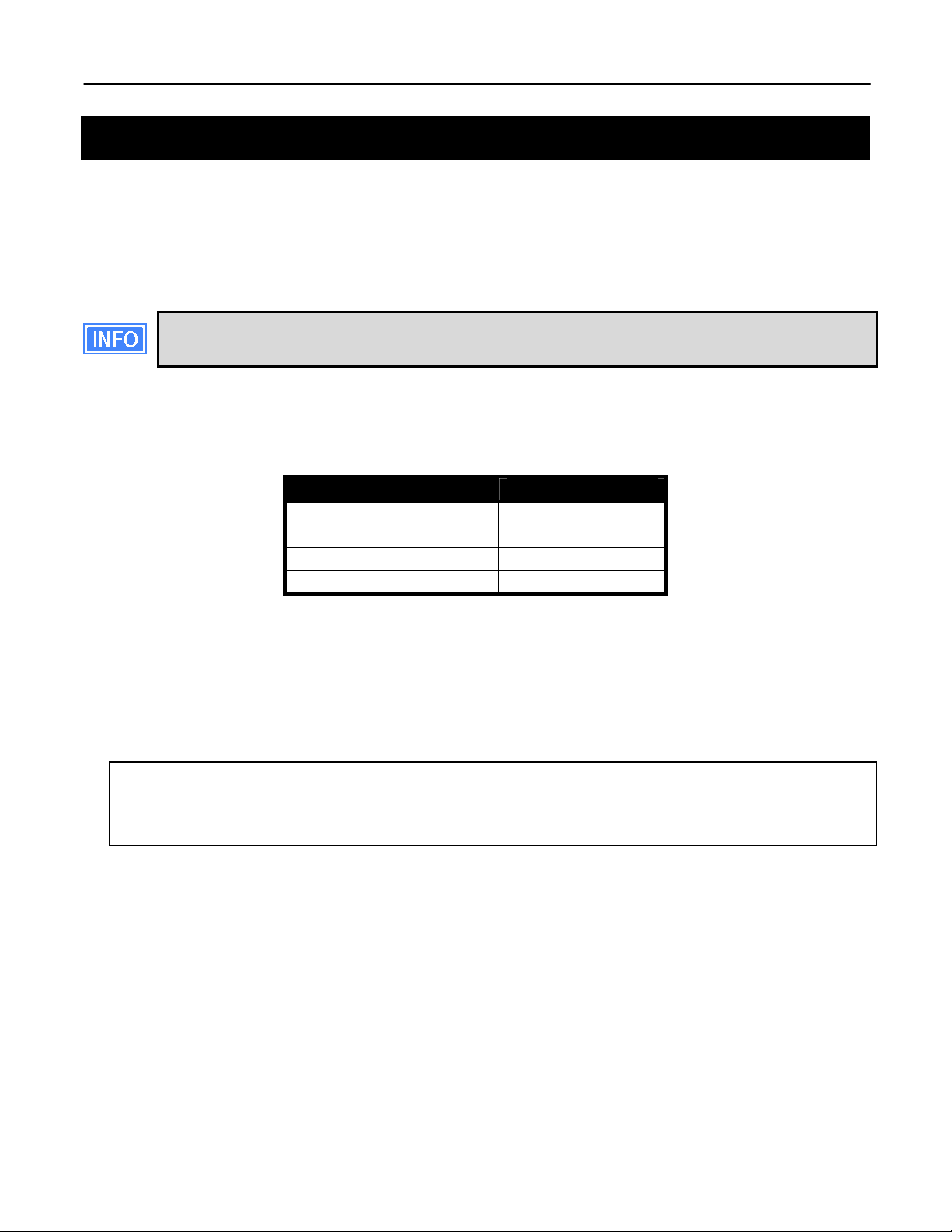
address on the same subnet as the EnRoute500. The parameters for the EnRoute500’s
configuration Ethernet interface are listed in Table 2.
Parameter Setting
IP address 169.254.253.253
Protocol SSH v2
User name admin
Default password mesh
Table 2. EnRoute500 Ethernet configuration interface settings
3. Attach the power cable supplied with the EnRoute500 to the power connector on the
bottom of the unit. The EnRoute500 will automatically power up.
4. Log in to the EnRoute500 using an SSH client. The IP address of the EnRoute500 is
169.254.253.253, the user name is ‘admin’, and the default admin password is ‘mesh’.
Last login: Mon Feb 20 23:11:57 2006 from 169.254.253.1
Shell timeout: 360 minutes.
Press '?' for help..
>
Figure 13. Prompt after login
5. After logging in, you will be presented with a prompt similar to that shown in Figure 13.
Enter
use mesh0
to select the mesh interface.
6. Use
set txpower=<tx power>
to set the transmit power of the mesh radio.
05648-01 Rev. A4
14
Page 15
EnRoute500 Installation Guide
You must set the value of ‘mesh0.txpower’ to be in the range from 1 to 60 to be
in compliance with FCC regulations.
7. Enter
use wlan1
to select the wlan1 interface.
8. Use
set txpower=<tx power>
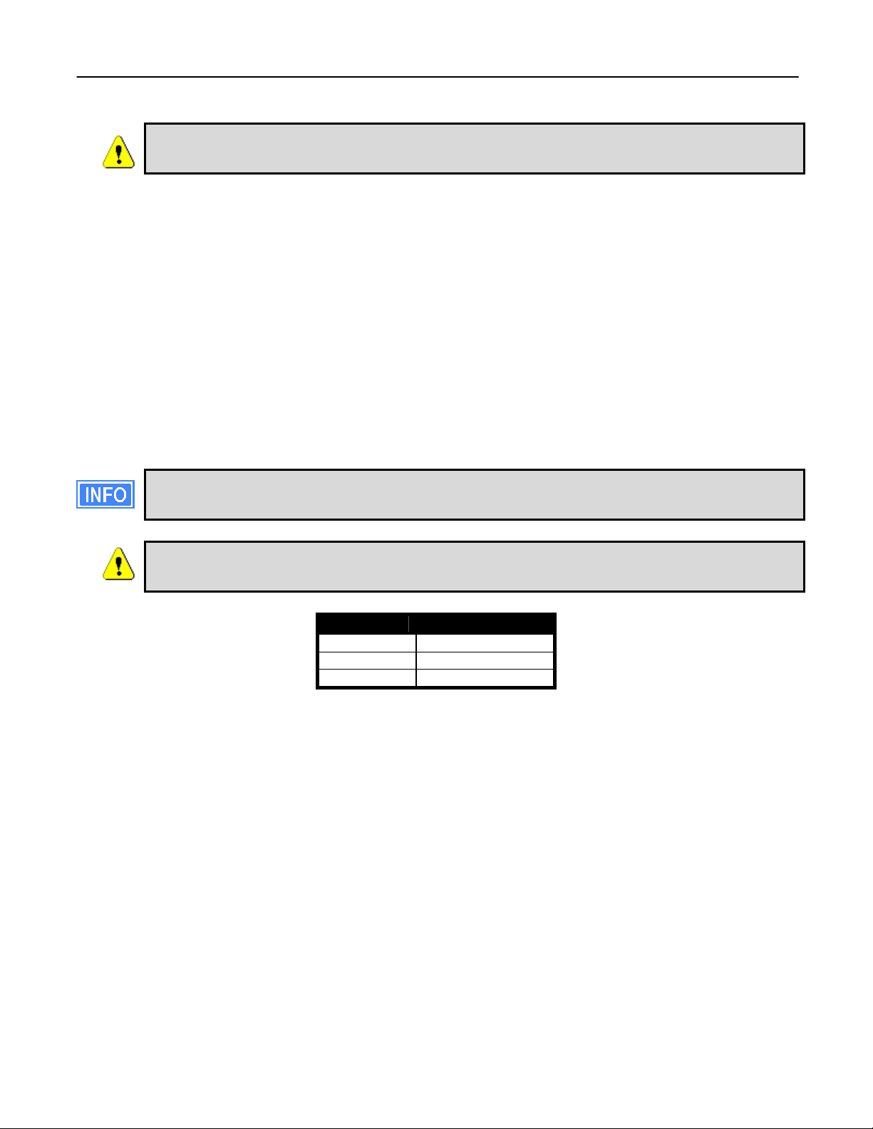
to set the transmit power of the access point radio. The maximum allowed value for
‘txpower’ depends on the access point channel that has been selected, as shown in
Table 3. The minimum allowed value is 1.
To determine the currently selected channel for the access point, use the command
‘show channel’.
You must set the value for ‘wlan1.txpower’ to be in the ranges shown in Table
3 to be in compliance with FCC regulations
Channel txpower setting
1 13
2 – 10 25
11 05
Table 3. Access point transmit power limits
9. Repeat step 8 for all APs that are enabled on the EnRoute 500. To select a new access
point to configure, use the command
use wlanN
where N is in the range from 1 to 4.
05648-01 Rev. A4
15
 Loading...