


&;
Conductivity Transmitter CX2000 S/N: 123456789
ACT
B.L.
10.00
ʳ Intelligent
ʳ ʳ Conductivity
Transmitter
Operation
Manual
Lin
10.00
PM 12:00
2013/04/10
SETUP
Conductivity Transmitter CX2000 S/N: 123456789
CAL
MODE
mS/cm
MTC
25.0 C
ENTER
ACT
B.L.
1

Precautions for installation
!
!
!
!
!
!
!
!
!
!
!
!
!
!
!
!
!
!
!
!
!
!
!
!
Wrong wiring will lead to breakdown or electrical shock of the instrument, please read this
operation manual clearly before installation.
zMake sure to remove AC power from the controller before wiring input, output connections,
and remove it before opening the controller housing.
zThe installation site of the controller should be a well ventiled area and out of direct sunlight.
zThe material of signal cable should be special coaxial cable. We strongly recommend using our
coaxial cable.
zAvoid electrical surges when using power, especially when using three-phase power. Use
ground wire correctly.
zThe internal relay contact of the instruments is for alarm or control function. To ensure safety,
please connect to external relay which can withstand enough amperage to allow safe
operation of the instruments.˄Please refer to chapter 3.6ʳ“Illustration of electrical
connectionϙ˅

CONTENTS
Precautions for installation
Brief Instruction 1
1. Specifications 4
2. Assembly and installation
2.1 Transmitter installation 5
2.2 Illustration of panel mounting 5
2.3 Illustration of Wall mounting and pipe mounting 6
3. Overview of conductivity / resistivity transmitter EC-4110
3.1 Illustration of rear panel 7
3.2 Illustration of terminal function ˊ
3.3 Description of terminal function ˋ
3.4 Wiring of cable ˌ
3.5 Circuit of cable ˌ
3.6 Illustration of electrical connection 10
4. Configuration
4.1 Illustration of front panel 11
4.2 Keypad 11
4.3 LED indicators 11
4.4 Display 12
5. Operation
5.1 Measurement mode 13
5.2 Set-up menu 13
5.3 Calibration menu 13
5.4 Shortcuts 13
5.5 Reset 13
5.5.1 Set-up reset 13
5.5.2 Calibration reset 13
6. Settings
Block diagram of settings 14
6.1 Entry of set-up menu 16
6.2 Security code of settings(Code) 17
6.3 ˟˴˺˴˺˸
6.4 Measurement parameters(Mode)
6.5 Product Adjustment 20
6.6 Temperature 21
6.7 Compensation 22
18
19

6.8 Relay 1 23
6.9 Relay 2
6.10 Wash time(Clean) 25
6.11 Analog output 1 (Cond/Res) 26
6.12 Analog output 2 (˧emperature)
6.13 Date/Time (Clock) 28
6.14 Sample average of measurements (Digital filter) 29
6.15 Backlight settings 30
6.16 Contrast settings 31
6.17 Power frequency (Freq.) 32
6.18 Automatically back to measurement mode(Return) 33
7. Calibration
Block diagram of Calibration 34
7.1 Entry of calibration menu 35
7.2 Automatically back to measurement mode(Return) 36
7.3 Security password of calibration 37
7.4 Cell constant calibration (CELL Const.) 38
7.4.1 Resistivity (Res) 38
24
27
7.4.2 Conductivity (Cond) 39
7.5 Standard solution calibration (Std. Sol.) 40
8. Error messages (Error code) 41
9. Installation of cells
9. Correct installation 42
9. Incorrect installation 43

Brief Instruction
1
Description of set-up settings (see chapter 6 for details) ʳʳʳʳʳʳʳʳʳʳʳʳʳʳʳʳ
Press and simultaneously to see the overview of the set-up settings. Then press I
if you would like to modify set-up settings.
.H\SDGIndex
.eypad )XQFWLRQ Description
Back to upper lHYHO
Choose change to left page
Increase digit
Choose change to right page
Decrease digit
Confirm settings after modifications and then go WR nextVWHS
Selection of set-up items
.eypad )XQFWLRQ 'escription
Mode Measurement mode, to choose Resistivity (Res) or Conductivity
(Cond) measurement
Temperature Temperature measurement and compensation, including MTC,
PTC, NTC MTC---Manual temperature compensation,
PTC/NTC--- auto temperature compensation
Relay 1 First relay setting, to select OFF or Hi/Lo alarm
Relay 2 Second relay setting, to select OFF or Hi/Lo alarm
Clean Automatic wash time setting, to choose electrode clean
equipment’s ON and OFF duration
Analog 1 Current output -Res or Cond
Analog 2 Current output -temperature

Clock
2
Clock setting ('XULQJORVV of power the
instrument’s time
will return to the facory setting)
Black-light Backlight setting, to set Auto/ON/OFF backlight, brightness,
and sensitivity
Contrast Contrast of screen setting
Digital Filter Takes every serial 1~60 measurements and averages them
continuously and displays the average readings
Return Setting of returning to the measurement mode
Code Security code of set-up mode. The factory default is 1111, and a
designated user can change the code.

Description of calibration settings (see chapter 7 for details)ʳ ʳʳʳʳʳʳʳʳʳʳʳʳʳ
3
Press and simultaneously to see the last calibration information. Then press if you
would like to make a new calibration or modify setting of calibration. Press keypad according to
index of keypad on the screen.
Index of keypad:
keypad Accordingly item Description
Back to upper layer
CKDnge to left page
Increase digit
CKange to right page
Decrease digit
Confirm settings after modifications and then go through next
step
Selection of calibration items (up to three-point calibration)
keypad Accordingly item Description
Code Security code of calibration mode. The factory default is 1100.
Return Time interval setting of returning to the measurement mode
Cell Constant To adjust the instrument cell constant setting WRPDWFK the
YDOXHRIWKH cell constant of the sensor
Solution Use the appropriate standard solution to calibrate the system
Note ʳ
Sensorex reserves the right to change the figure of icons and contents. For the actual icons and contents
please refer to the instruments.

1. Specifications
!
!
!
!
!
!
!
!
!
!
!
!
!
!
!
!
!
!
!
4
Model!
Measuring modes
Ranges
Resolutions
Accuracy
Temperature
Compensation
Calibration mode
Ambient Temp.
Resistivity
Conductivity
Tem p.
Resistivity
Conductivity
Tem p.
Resistivity
Conductivity
Tem p.
CX2000
0.00 S/cm~200.0 mS/cm manual or auto range selectable
Manual temperature compensation selectable
(1)Cell constant adjustment (2)Standard solution calibration
Resistivity/Conductivity/Temp.
0.00 M·cm~20.00 M·cm
-30.0~130.0C
0.01 M·cm
0.01 S/cm
0.1C
±1% ± 1Digit
±1% ± 1Digit
±0.2C± 1Digit
NTC30K or PT1000 or
0~50 C
Storage Temp.
Cell Constant
Temperature Coefficient
Display
Analog output 1
Analog output 2
Contact
Settings
Activate
Wash
Certification
Power Supply
Installation
-10~70 C
0.01, 0.05, 0.1, 0.5, 10.00 cm
freely selectable 0.008~19.99 cm
Linear temperature compensation from (0.00%~ 40.00%)
and Non-Linear compensation
Large LCD display with environment light sensor
auto/manual illumination function
Isolated DC 0/4~20mA corresponding to main measurement,
max. load 500:
Isolated DC 0/4~20mA corresponding to Temp., max. load 500:
RELAY contactΔ240VAC 0.5A Max.(recommend)
Two sets of individual HIGH or LOW programmable control
RELAY contact: ON 0~99min. 59sec. / OFF 0~999hr 59min.
IP65 (NEMA 4)
100V~240VAC±10%Δ50/60HzΔ5W max.
Wall or Pipe or Panel Mounting
-1
fixed,
-1
Dimensions
Cut off Dimensions
Weight
Note: The specifications are subject to change without notice.
96m × 96mm × 132mm (HuWuD)
93 mm u 93 mm (HuW)
0.5Kg
2. Assembly and installation
m
m
5
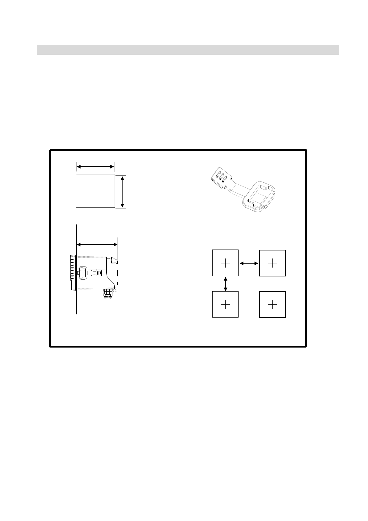
2.1 Transmitter installation: This Transmitter can be installed through panel mounting, wall
mounting and pipe mounting.
Installation of panel mounting: Firstʿ prepare a square hole of 93 x 93mm on the panel box,
and then insert the controller directly into the panel box. Insert the accessorial mounting bracket
from the rear, until it is locked into pickup groove.
2.2 Illustration of panel mounting:
93 m
93 mm
Hole size
112 m
Illustration of panel mounting,
fixed with mounting bracketʳ
Mounting bracket
Ѐ
87 mm
87 mm
Ѐ
Hole distances on the panel box
Ѐ
Ѐ


3.3 Description of terminal function:
ѽѾ
ѽѿ
ѽҀ
ѽҁ
ѽ҂
ѽ҃
҄
ѽ҅
ѽ҆ ʳ
Ѿѽ
ѾѾ ʳ
Ѿѿ
ѾҀ
Ѿҁ
Ѿ҂
Ѿ҃
Ѿ҄
Ѿ҅
Ѿ҆
ѿѽ ʳ
ѿѾʳ ʳ ʳ ʳ ʳ ʳ ʳ ʳ
ѿѿʳ ʳ ʳ ʳ ʳ ʳ ʳ ʳ
ѿҀʳ ʳ ʳ ʳ ʳ ʳ ʳ ʳ
ѿҁʳ ʳ ʳ ʳ ʳ ʳ ʳ ʳ
8
REL1ΚExternal relay terminal first control
REL2ΚExternal relay terminal second control
WA SHΚExternal wash relay terminal
ѽ҄
ʳ NCΚNone contact
100~240ACΚPower supply terminal
NCΚNone contact
ʳ 100~240ACΚPower supply terminal
SHIELDΚThe transparent cell connection line
CELL1ΚThe cell connection line: Current electrode 1
CELL3ΚThe cell connection line: Voltage electrode 2
CELL4ΚThe cell connection line: Current electrode 2
ʳ
CELL2ΚThe cell connection line: Voltage electrode 1
SGΚNC
TPΚConnect the cell connection line of temperature probe
SGΚNC
4~20mAЀterminalΚMaster measure current output terminal +, for external
recorder or PLC control
4~20mAЁterminalΚMaster measure current output terminal -, for external
recorder or PLC control
4~20mAЀterminal / D+(B)ΚTemperature current output terminal +, for
external recorder or PLC control
4~20mAЁterminal / GΚTemperature current output terminal -, for external
recorder or PLC control
NC / D-ΰAαΚNC


3.6 Illustration of electrical connection:
10
100 ~ 240VAC
Transmitter
Surge absorber
Surge absorber
Surge absorber
Washing device
Dose feeder
Dose feeder
Surge absorber
External relay
Surge absorber
External relay
Surge absorber
External relay

4. Configuration:
ʳ ʳ ʳ ʳ ʳ ʳ ʳ ʳ ʳ ʳ ʳ ʳ ʳ ʳ ʳ ʳ ʳ ʳ ʳ ʳ ʳ ʳ ʳ ʳ ʳ ʳ ʳ
11
Conductivity Transmitter CX2000 S/N: 123456789
ACT
B.L.
10.00
4.1 Illustration of front panel:
10.00
PM 12:00
2013/04/10
Lin
mS/cm
MTC
25.0 C
ACT
B.L.
SETUP
CAL
Conductivity Transmitter CX2000 S/N: 123456789
MODE
ENTER
4.2 Keypad:
In order to prevent inappropriate operation by others, before the parameter setting and
calibration, the operation applies multi-keysʿʳand coding protection if necessary. Description of
the key functions is in the following:
ΚIn the parameter set-up mode, pressing this key allows you exit parameter set-up mode
and back to Measurement mode.
ˍ In the Calibration mode, pressing this key allows you exit Calibration mode and back to
Measurement mode.
Κ1. In the parameter set-up mode and Calibration mode, pressing this key to select
leftward or change to another page.
2. When adjusting value, press this key to increase the value.
Κ1. In the parameter set-up mode and Calibration mode, pressing this key to select
rightward or change to another page.
2. When adjusting value, press this key to decrease the value.
ΚKey for confirmation; pressing this key is essential when modifying data value or
selecting the parameter setting items in the window.
4.3 LED indicators:
ACTΚWashing device operation indicator ˴˷ʳ˶ontrolling operation indicator (Relay 1ΕRelay 2)
B.L. : Light sensor; in the automatic display backlit mode, the lamp will light or go out as the
change of environmental brightness.

4.4 Display:
12
:Measurement mode
:Set-up mode
:Calibration mode
Control function
on hold
Clock
RELʳ1ʳhighʳʳ
˿ point alarm
RELʳ˅ʳhighʳʳ
˿ point alarm
Analog 1 output
current over range
alarm
Analog 2 output
current over range
alarm
Compensation unit
Meaurementʳ˼
Temperature
compensation mode
(MTC/ATC)
Temperature valueʳ
˴˷ʳ˼
Wash device in
action condition
Note: 1. When the wash device is turned on, the display shows and flashes the description, “Clean
Running”. At the same time, the ACT indicator LED lights up, and the transmitter
automatically turns off Relay 1 and Relay 2 function. After finishing cleaning, elay 1
and Relay 2 will automatically return to normal status.
2. When Relay 1 which is set in high setting point is in action, the display shows and flashes
the description, “REL 1_Hi”, and ACT indicator LED lights up. When Relay 1 which is set
in low setting point is in action, the display shows and flashes the description, “REL 1_Lo”,
and ACT indicator LED lights up.
3.When Relay 2 which is set in high setting point is in action, the display shows and flashes
the description, “REL 2_Hi”, and ACT indicator LED lights up. When Relay 2 which is set
in low setting point is in action, the display shows and flashes the description, “REL 2_Lo”,
and ACT indicator LED lights up.
4. When under measurement mode, if the temperature compensation mode is set in MTC
(Manual adjustment), press or to adjust the MTC temperature manual.

5. Operation
ʳ ʳ ʳ ʳ ʳ ʳ ʳ ʳ ʳ ʳ ʳ ʳ ʳ ʳ ʳ ʳ ʳ ʳ ʳ ʳ ʳ ʳ ʳ ʳ
13
5.1 Measurement mode:
ʳʳʳAfter all electrical connections are finished and tested, connect the instrument to the power
supply and turn it on. The transmitter will automatically enter measurement mode with the
factory default settings or the last settings from user.
5.2 Set-up menu:
ʳʳʳPlease refer to the set-up instructions in Chapter 6. Press and simultaneously to
enter into set-up menu, and press toʳgo press to back to measurementʳmode.
5.3 Calibration menu:
ʳʳʳPlease refer to the calibration instructions in Chapter 7. Press and
simultaneously to enter into calibration menu, and press to go back to measurementʳmode.
5.4 Shortcuts: In the measurement mode, if selecting MTC for temperature compensation mode, you
may press and to adjust MTC temperature value.ʳ
5.5 Reset:
5.5.1 Master reset:ʳʳʳʳʳʳʳʳʳʳʳʳʳʳʳʳʳʳʳʳʳʳʳʳʳʳʳʳʳʳʳʳʳʳʳʳ
Measurement mode: Conductivity, Auto-Range
Temperature compensation: MTC 25ć
Temperature Coefficient: Lin, 2.00%
Relay 1ΚHigh point alarm: AUTOʿʳSP1= 100.0mSΔDB=10.0mS
Relay 2ΚLow point alarm: AUTOʿʳSP2 =10.0 mSΔDB= 1.00 mS
Wash time: OFF
Analog 1 current output (Cond/Res)Κ420 mAΔ0.00199.9mS
Analog 2 current output (Temp)Κ(Temp)Κ420 mAΔ0100.0C
Display backlit:ʳOFF
Contrast: 0
Code: OFF
Date & TimeΚ2010/1/1 00:00:00
Auto back: Auto, 3 minutes
5.5.2 Calibration reset:
Cal TimeΚ2010/01/01
Cal TypeΚNo Cal
Cell ConstantΚ0.5000
Cal Temp.Κnone
Auto back: Auto, 3 minutes
Note: The factory default of calibration presetting is “No Cal”, and the cell constant setting is “0.5000”.
It means that the user has not calibrated the sensor with the transmitter yet. When selecting
standard solution to finish calibration, the display shows cell constant of the cell and the value of
the standard solution.

6. Settings
ʳ ʳ ʳ ʳ ʳ ʳ ʳ ʳ ʳ ʳ ʳ ʳ ʳ ʳ ʳ ʳ ʳ ʳ ʳ ʳ ʳ ʳ ʳ ʳ ʳ ʳ ʳ ʳ ʳ ʳ ʳ ʳ ʳ ʳ ʳ ʳ ʳ ʳ ʳ ʳ ʳ ʳ ʳ ʳ ʳ
14
Block diagram of settings 1:
Settings
Overview
Return
Setting
Code
Setting
Code Input
OFF ON
New
Code
Setting
Ɠ
Ɠ
Ɠ
Setting Mode
Mode
Setting
Res/Cond
mode select
Cond
Range
select
5HVLVWLYLW\
PRGHRQO\
Product Adj.
Setting
OFFON
ResCond
MTC
ATC
Value
Value
correc
correc
-tiont
-tion
Modify
CF
Temperature
Setting
Compensation
mode
MTC PTC
Value
input
Value
correct
NTC
Value
correct
Lin
T.C.
value
input
T.C.
Setting
Non-Lins
Relay1
Setting
Relay1
ON/Off
select
Relay 1
Hi/Lo select
Relay 1
SP input
Relay 1
DB input
Relay 1
Test
Relay2
Setting
Relay2
ON/Off
select
Relay 2
Hi/Lo select
Relay 2
SP input
Relay 2
DB input
Relay 2
Test
Clean
Setting
Clean
ON/Off
select
Clean ON
time input
Clean OFF
time input
Clean
DB input
Clean
Test
Cond/Res
Settom g
Continued on next page
˕˴˶˾ʳʳ˻˸ʳ˸˼
˶˿˴ʳ˂ʳ˴˶˼ˍ
Continued on next page

Block diagram of settings 2:
15
Connected with previous page
Clean
Setting
Cond/Res
current
output 1
0/20 or
4/20mA
mode select
Relative
value to 0 or
4mA
Relative
value to
20mA
Κ
Κ
Temp
current
output 2
0/20 or
4/20mA
mode select
Relative
value to 0 or
4mA
Relative
value to
20mA
Clock
Setting
Year
Input
Date
Input
Time
Input
Digital
Filter
Setting
Signal
average
Auto ON OFF
Bright-
ness
setting
Sensi-
tivity
setting
Backlight
Setting
Mode
select
Bright-
ness
setting
Contrast
Setting
Contrast
Input
Freq.
Setting
Freq.
Select
Auto
Return
time
input
Return
Setting
Method
select
Code
Setting
Manual
Connected with previous page
Κ
Back to the previous
class / action:

16
6.1 Entry of set-up menu
In the measurement mode, pressing the two keys and simultaneously allows
you enter the overview of current setting, and press to enter the set-up mode to
modify the setting if necessary.
“Measurement (Mode)”
Pressʳʳor
Pressʳʳor
Pressʳʳto confirm it
Enter set-up menu
Pressʳʳ

17
6.2 Security code of settings:
After entering set-up mode, select “code” item, press to enter into code
procedure. The pre-set code is 1111.
Note: Set the code of setting mode prior to the code for calibration. That means that
the code of setting mode can be used for the code of calibration mode.
When a wrong password
is keyed in, the display
shows “Error 5”, press
to re-key in it, or press
to exit.
(Select to turn on or turn off
code protection function. If
you select turn on, please
key in a new code. There
will be a code requirement
showing in display when you
re-enter to the setup mode.
Key in the correct password
to enter into setup mode.)
Press to confirm it.
Press to confirm it.
Press or
或 鍵
The first ‘0” of digits ‘0000” start
to twinkle. Press or to
adjust the value, and then press
to confirm it and continually key
in the next digit, and so on.
Press to confirm it.
Key in new password
Press to confirm it.
Enter “Language” Setup

18
6.3 Language
Enter Language setup menu, select the system language from English, Traditional
Chinese and Simplified Chinese.
Press to confirm it.
Pressʳ or ʳʳ
to select language
type.
Press to confirm it.
Enter “Measurement Mode” Setup

19
6.4 Mode
Enter setup of “Mode”. Select between “Conductivity (Cond)” or “Resistivity
(Res)” measurement. If select “Conductivity”, then the range limit needs to be selected
from AUTO, 20.00S, 200.0S, 2000S, 20.00mS or 200.0mS.
Select “Res”.
Press to confirm it.
Press to confirm it.
Select “Cond”.
Press to confirm it.
Select “mS/cm”.
Press to confirm it.
Select “GEAR”.
Press to confirm it.
Select “S/cm”.
Press to confirm it.
Select “GEAR”.
Press to confirm it.
Select “AUTO”.
Press to confirm it.
Enter ”Temperature” Setup
Enter ”Product Adjustment” Setup

20
6.5 Product Adjustment (Resistivity mode only)
Enter setup of product Adjustment to make the fine adjustment of the measurement
reading. For ultra-pure water application, the function can increase the resolution of cell
constant, and it makes users to adjust the cell constant through a Cell Factor (CF
adjustable range: 0.7000~1.3000). It also allows two decimal of the temperature display
which increases the sensitivity of cell constant and temperature change and achieves the
fine adjustment of reading up to 0.01Meg ohm. It helps the users to see the small
change of reading or trend in ultra-pure water application.
Press to confirm it.
Press or
to switch
on or switch off.
ATC Mode MTC Mode
Use standard
thermometer to test
the actual temperature
of the solution, and
press or
to input the correct
temperature value.
Users may compare the reading with the
actual measured resistivity value. Press
or to adjust the Cell Factor( a
cell constant’s multiplier) in the main
display in order to modify the reading of
If necessary, compare
with the actual
temperature value
tested by standard
thermometer.
Press or
to input the modified
value.
measurement which shows in the bottom
part of display.
Enter “Temperature” Setup

21
6.6 Temperature
Enter setup of “Temperature” to select temperature compensation mode. Select from
NTC(NTC 30K), PTC(PT 1K) or MTC(Manual adjustment), or you may press &
simultaneously to back to default setting. In the measurement mode, if selecting MTC
for temperature compensation mode, you may press or to adjust MTC
temperature value.
Press to confirm it.
Press
or to select
Press to confirm it.
Press
or to select
Press to confirm it.
Use standard thermometer to test
the actual temperature of the
solution, and press or
to input the correct temperature
value.
If necessary, compare with
the actual temperature value
tested by standard
thermometer.
Press or to
input the modified value.
Press to confirm it.
Enter “Compensation” Setup

22
6.7 Compensation
Enter setup of compensation mode, and select Linear Compensation or Non-linear
compensation mode. According to your measurement need for temperature coefficient,
you may select linear (Lin), non-linear (nLin), or non-compensated (Lin 0.00%).
Normally, select linear compensation for conductivity measurement(Cond)(Range:
0.00%~40.00%), and select non-linear compensation for Resistivity measurement.
Temperature coefficient (hereinafter referred to as TC): Conductivity of solution
increases with temperature increase. The relationship is as follows:
C
Ct
T
Conductivity at 25C
25
Conductivity at TC
Measured solution temperature
Formula 1ΚCt = C
Formula 2Κ= ( CtЁC25 ) / { C25 ( TЁ25 )}
{ 1+( TЁ25 ) }
25
Temperature compensation
How to get TC of solution: For obtaining higher accuracy of measurement, you may
calculate the TC value according to the formulas above and set an appropriate TC value
for the instrument. Take an example for 0.01N KCl. Set the TC of the instrument to
non-compensatedΰLin, 0.00иα, and control the temperature at 25C and at 20C.ʳC
means the measurement value at 25C(Such as C
measurement value at 20C(Such as C
= 1278S). According to the formulas above,
25
= 1413S). Ct means the
25
25
Ј1.91%.
Press to confirm it.
Pressʳ or ʳʳ
to select Linear or
Non-linear
com
pensation.
Press to confirm it.
The range of linear compensation:
0.00% ~ 40.00%
Pressʳ or ʳʳ
to set percentage
Linear compensation.
MAX: 40.00%
Default: 2.00%
Enter “Relay 1” Setup

23
6.8 Relay 1
Enter setup of Relay 1. Select the item to turn on or turn of the relay 1 function. If you
select to turn on the relay 1, then select for using relay 1 as “Hi set-point” alarm or
“Low set-point” alarm. Set the value of set-point (SP) and dead-band (DB). The range
for set-point isʳ00.00M~19.99 M/00.00s~1999mS; while the range for DB is
00.00M~2.00 M/00.00s~19.99mS.ʳ(The measurement unit is depending on the use
of measuring range)
Press to confirm it.
Press to confirm it.
Press or to adjust
set-point (SP) value.
If the measuring range of
conductivity measurement is set
as AUTO, then it needs to be set
unit((S /cm or mS/cm), value,
and decimal point by order.
Press ʳ or
to select to activate
REL1 or not. If
not, the guide
menu goes to setup
of Relay 2.
Press or to adjust
dead-band(DB) value
Press to confirm it. Press to confirm it.
Press ʳ or
to select use REL1
as Hi point or Lo
point alarm.
Press ʳ or
to select to activate
a test of REL1 or
not. If “ON”, the
relay 1 is in action,
and the “ACT”
indication light
will light up.
Press to confirm it.
Press to confirm it.
Enter “Relay 2” Setup

24
6.9 Relay 2
Enter setup of Relay 2. Select the item to turn on or turn off the relay 2 function. If you
select to turn on the relay 2, then select relay 2 as “Hi set-point” alarm or
“Low set-point” alarm. Set the value of set-point (SP) and dead-band (DB). The range
for set-point isʳ00.00M~19.99 M/00.00s~1999mS; while the range for DB is
00.00M~2.00 M/00.00s~19.99mS.ʳ(The measurement unit is depending on the use
of measuring range)
Press to confirm it.
Press to confirm it.
Press or to adjust
set-point (SP) value.
If the measuring range of
conductivity measurement is set
as AUTO, then it needs to be set
to S /cm or mS/cm value,
and decimal point by order.
Press to confirm it.
Press to confirm it.
Press ʳ or
to select to activate
REL2 or not. If
not, the guide
menu goes to setup
of Clean.
Press ʳ or
to select use REL2
as Hi point or Lo
point alarm.
Press or to adjust
dead-band(DB) value
Press to confirm it.
Press ʳ or
to select to activate
a test of REL2 or
not. If “ON”, the
relay 2 is in action,
and the “ACT”
indication light
will light up.
Press to confirm it.
Enter “Clean” Setup

25
6.10 Clean
Enter setup of “Clean” function. Select the icon to turn on or turn off the clean function.
If you select “Auto” turning on, this sets the timer of the clean function including
automatically turning on time and turning off time, and the bead-band value(DB).
Note: When the clean function is turned on, if any value is set to 0, the instrument
will automatically turn off this function.
Press or to adjust
set-point(SP) value
Press to confirm it. Press to confirm it.
Press ʳ or
to select to activate
Clean or not. If
not, the guide
menu goes to setup
of Analog 1.
Press or to adjust
dead-band(DB) value
Press to confirm it.
Press ʳ or
to adjust the auto
turning on time.
Press to
confirm the
minute part, and
move to adjust
the second part.
Press to confirm it.
Press to confirm it.
Press ʳ or
to select to activate
a test of Clean or
not. If “ON”, the
Clean function is in
action, and the
“ACT” indication
light will light up.
Press to confirm it.
Enter “Analog 1” Setup

26
6.11 Analog output 1 (Cond/Res):
Enter setup of Analog 1. Select 0~20mA or 4~20mA current output. Set the related
value to the range of Cond./Res. measurement. If the range of the Cond./Res.
measurement is set smaller, the resolution of current output is higher. When the
measurement value exceeds the upper limit of setting range, the current output remains
at around 22mA. When the measurement value exceeds the lower limit of setting range,
the current output remains at 0mA under 0~20mA mode, or the current output remains
at around 2mA under 4~20mA mode. The phenomenon can be used as a judgment
reference of abnormality. If under HOLD status, the current output will remain at last
current output value before the HOLD status is activated. For the convenience of
connecting external recorder or PLC controller, the current output will remain 0/4mA or
20mA while setting its relative measurement value.
Press to confirm it.
Press to confirm it.
Press ʳ or
to select to current
output range,
0-20mA or
4-20mA.
Press or to
set the lower limit of
Cond. value relative to
4.0mA output signal. If
the measuring range of
conductivity
measurement is set as
AUTO, then it needs to
be set unit((S /cm or
mS/cm), value, and
decimal point by order.
Press to confirm it.
Press or to
set the upper limit of
pH value relative to
20.0mA output signal.
Press to confirm it.
Press or to
set the lower limit of
Cond. value relative to
0.0mA output signal. If
the measuring range of
conductivity
measurement is set as
AUTO, then it needs to
be set unit((S /cm or
mS/cm), value, and
decimal point by order.
Press to confirm it.
Enter “Analog 2” Setup(Temperature)

27
6.12 Analog output 2 (Temperature):
Enter setup of Analog 2. Select 0~20mA or 4~20mA current output. Set the related
value to the range of temperature measurement. If the range or the temperature
measurement is smaller, the resolution of current output is higher. When the
measurement value exceeds the upper limit of setting range, the current output remains
at around 22mA. When the measurement value exceeds the lower limit of setting range,
the current output remains at 0mA under 0~20mA mode, or the current output remains
at around 2mA under 4~20mA mode. If under HOLD status, the current output will remain at the last
current output value before the HOLD status is activated.
Press to confirm it.
Press to confirm it.
Press ʳ or
to select to current
output range,
0-20mA or
4-20mA.
Press or to
set the lower limit of
Temp. value relative to
4.0mA output signal.
Press or to
set the lower limit of
Temp. value relative to
0.0mA output signal.
Press to confirm it.
Press or to
set the upper limit of
Temp. value relative to
20.0mA output signal.
Press to confirm it.
Enter “Date/Time(Clock)” Setup

28
6.13 Date/Time(Clock)
Enter setup of Date/Time(Clock). Set the “Year”, “Month”, “Date”, “Hour”, and
“Minute” time. Note: The clock needs to be reset in the event of a power failure.
Press to confirm it.
Press or to
set the year.
Press to confirm it.
Press or to
set the month part, and
press to move to
adjust the date part.
Press to confirm it.
Press or to
set the hour part, and
press to move to
adjust the minute part.
Enter “ Sample average of measurements
(Digital Filter) ” Setup

29
6.14 Sample averaging of measurements (Digital Filter)
Enter the setup of Digital filter. You may select the number of samples to be averaged
each time to increase the stability of measurement.
Press to confirm it.
Press or to
set the number of
sample to be averaged.
Press to confirm it.
Enter “Back Light” Setup

30
6.15 Backlight settings
Enter setup of backlight display. As needed, you can set the brightness of
display(-2~2, dark~ bright) and sensitivity of the baclight sensor(-2~2, insensitive~
sensitive).
ON: Backlight light up OFF: Backlight turns off & Touch-on mode
AUTO: According to ambient condition turn on & off automatically & Touch-on mode
Press to confirm it.
Press or
to select
backlight mode.
Press to confirm it.
Pressʳ or ʳʳ
to
select -2, -1, 0,
1, 2, five
Backlit
Brightness
levels
Press to confirm it.
Pressʳ or ʳʳ
to select
-2, -1, 0, 1, 2, five
Backlit sensitization
levels.
Press or
to select
backlight mode.
Press to confirm it.
Pressʳ or ʳʳ
to
select -2, -1, 0,
1, 2, five
Backlit
Brightness
levels
Press to confirm it.
Press to confirm it.
Press to confirm it.
Enter “Contrast” Setup
Press to confirm it.

31
6.16 Contrast settings
Enter setup of display contrast. You can set the contrast of display according to your
need.
Press to confirm it.
Pressʳ or ʳʳ
to select display
contrast level.
Press to confirm it.
Enter “Power frequency (Freq)” Setup

32
6.17 Power frequency (Freq.)
Enter setup of power frequency. You may select power frequency setting of the
instrument 50Hz or 60Hz according to the local power frequency.
Note: This setting significantly affects the normal measurement of instrument, thus, be
sure to make the setting correctly.
Press to confirm it.
Pressʳ or ʳʳ
to select power frequency.
Press to confirm it. Press to confirm it.
Enter ”Auto return mode (Return)” Setup

33
6.18 Return
Enter setup of auto return mode (Return) to set the function that the instrument
automatically exit the setup menu after a period of time without pressing any key. The
“Manual Exit” means that it needs to exit setup menu manually, while “Auto” means
that the display automatically exit the setup menu and back to measurement mode after
a period of time without pressing any key.
Press to confirm it.
Pressʳ or ʳʳ
to select Auto return
or manual exit.
Press to confirm it.
Pressʳ or ʳʳ
to adjust “minute”
part, and press
to confirm it and
move to” second” part.
Press to confirm it.
Return to “Password (Code)”Setup
Press to confirm it.

7. Calibration
34
Block diagram of Calibration
Cal. Info.
Cal. mode
MTC
Temp.
adjust
CELL
Const.
CELL
constant
select
ATC
CELL
constant
adjust
Auto
Time
input
Return
setting
Manual
Exit
Std. Sol.
Std. Sol.
select
Std. Sol.
MTC
Temp.
adjust
Κ
Κ
adjust
ATC
calibrate
Indicate
CELL
constant
Code
setting
Code
input
OFF ON
New Code
input
Κ
Back to the previous class / action
or the end of the procedure:

35
7.1 Entry of calibration menu
In the measurement mode, pressing the two keys and simultaneously
allows you enter theʳCalibration Information. If you do not need to re-calibrate the
measurement system, press to go back to measurement mode. If you need to
re-calibrate the system, press to enter to the calibration setup menu.
Measurement mode
Press and simultaneously
ʳ
Press to confirm it.
Enter Calibration setup menu

36
7.2 Return
Enter setup of auto return mode (Return) to set the function that the instrument
automatically exit the setup menu after a period of time without pressing any key. The
“Manual Exit” means that it needs to exit calibration setup menu manually, while
“Auto” means that the display automatically exit the calibration setup menu and back
to measurement mode after a period of time without pressing any key.
Note: the return function of setup menu and calibration setup menu are independent
settings.
Press to confirm it.
Pressʳ or ʳʳ
to select Auto return
or manual exit.
Press to confirm it.
Pressʳ or ʳʳ
to adjust “minute”
part, and press
to confirm it and
move to ”second” part.
Press to confirm it.
Press to confirm it.
Enter “Password (Code)” Setup

37
7.3 Security password of calibration (Code)
Select the Code (password) icon after entering calibration setup mode. Select to
activate code function or not. The default Calibration setting code is “1100”.
If you input a wrong code,
then the display shows a
“Error 5” message. Press
to restart inputting another
code, or press to
exit the calibration menu.
Press to confirm it.
The first ‘0” of digits ‘0000” start
to IODVK. Pressor to
adjust th
to confirm it and continually key
in the next digit, and so on.
Press to confirm it.
e value, and th
en press
(Select to turn on or turn off
code protection function. If
you select turn on, please
key in a new code. There
will be a code requirement
showing in display when you
re-enter to the setup mode.
Key in the correct password
to enter into calibration setup
menu.)
If you input a wrong code,
then the display shows a
“Error 5” message. Press
to restart inputting another
code, or press to
exit the calibration menu.
Press or
Press to confirm it.
Input new code
Press to confirm it.
Enter “Cell Constant Calibration
(CELL Const.)”Setup

38
7.4 Cell constant calibration (CELL Const.)
7.4.1 Resistivity (Res)
Enter setup of cell constant to directly set cell constant. Press or to
select the preset value closest to your sensor's one. There are three sets of preset value
(0.01, 0.05, 0.10). Select the most appropriate cell constant value and press to
confirm it and enter to the next screen. At the time, the cell constant starts to flash.
Press or to adjust the cell constant value. Correct the measurement value to
known standard solution value by adjusting the cell constant, or setting the known cell constant
directly. Press to confirm it.
Resistivity cell constant setting range:
0.0100 Adjustable range: 0.0080 ~ 0.0120
0.0500 Adjustable range: 0.0400 ~ 0.0600
0.1000 Adjustable range: 0.0800 ~ 0.1200
Press to confirm it.
According to the cell constant of the
resistivity sensor, press or
to select the nearest preset value.
Press to confirm it.
Under MTC temperature mode, press
or to adjust temperature value.
If under ATC temperature mode(PTC or
NTC), the temperature value is read
automatically, and the instrument
directly goes to next screen.
Press to confirm it.
According to labeled cell constant of the
resistivity sensor, press or to
adjust to the corresponding value. Press
to confirm it.
Press to confirm it.
Enter “Standard solution calibtaion” mode

39
7.4.2 Conductivity (Cond)
Enter setup of cell constant to directly set cell constant. Press or to
select the preset value to near an appropriate one. There are four sets of preset values
(0.01, 0.10, 0.50, 10.00). Select the most appropriate cell constant value and press
to confirm it and enter to the next screen. At thLV time, the cell constant starts to )ODVK
. Press or to adjust the cell constant value. Correct the measurement
value to known standard solution value by adjustLQJWKH cell constant, or set the known cell
constant directly. Press to confirm it.
Conductivity cell constant setting range:
0.0100 Adjustable range: 0.0080Д0.1200
0.1000 Adjustable range: 0.0400Д0.6000
0.500 Adjustable range: 0.0800Д1.999
10.00 Adjustable range: 2.00Д19.99
Press to confirm it.
According to the cell constant of the
resistivity sensor, press or
to select the nearest preset value.
Press to confirm it.
Under MTC temperature mode, press
or to adjust temperature value.
If under ATC temperature mode(PTC or
NTC), the temperature value is read
automatically, and the instrument
directly goes to next screen.
Press to confirm it.
According to labeled cell constant of the
conductivity sensor, press or
to adjust to the corresponding value.
Press to to confirm it.
Enter “Standard solution calibtaion” mode
Press to confirm it.

40
7.5 Standard solution calibration (Std. Sol.)
Applying known standard solution for calibration is only suitable for
conductivity measurement mode. Press or to select from preset standard
solution value. There are three preset value from 84.0S/cm, 1413S/cm, to
12.88mS/cm. After selecting proper preset value, put the cleaned conductivity sensor
into standard solution, and press to enter the calibration screen. At the time, the
conductivity value can be adjusted according to standard solution value. Press to
initiate the calibration. The display shows the sign , and it starts the auto
calibration procedure. After finishing calibration, the display automatically shows the
cell constant after calibration. Press to exit.
Press to confirm it.
Press or to select it.
Press or to adjust the
standard solution value. Press
to confirm it.
Under MTC temperature mode, press
or to adjust temperature value.
If under ATC temperature mode(PTC or
NTC), the temperature value is read
automatically, and the instrument
directly goes to next screen.
The system measure the
standard solution. Press to
show the reading, or wait for
the reading which shows
automatically.
Display shows calculated
cell constant value
Enter ”Auto return
mode (Return)” Setup

41
8. Error messages (Error code)
Messages Reason Dispositions
Error9
Error3
Error2
Error1
Serious error that does
not permit any further
measuring
Please call Customer service.
Wrong password Re-enter a password
Cell constant of the electrode
exceeds the upper or lower
limit
The readout is unstable when
calibration
1. Replace with new standard
solution
2. Maintain the electrode or
change to a new electrode, and
make another calibration
1. Replace with new standard
solution
2. Maintain the electrode or
change to a new electrode, and
make another calibration

42
9. Installation of cells
9.1 Correct installation of cells

43
9.2Incorrect installation
9.2 .1 Insufficient immersion: This installation can result in stagnant water inside
the cell and thus lead to measurement error.
9.2.2 Insufficient water flow: This installation is prone to error due to
insufficient water flow.
9.2.3 Insufficient immersion: This installation can result in stagnant water inside
the cell and thus lead to measurement error.

 Loading...