

Page 1
PCI Express
4-Channel
Frame G
rabber
User’s Manual
Model 810 | Rev.A | September 2013
Page 2

Table of Contents
TABLE OF CONTENTS .................................................................................................2
LIMITED WARRANTY ..................................................................................................4
SPECIAL HANDLING INSTRUCTIONS............................................................................5
INTRODUCTION .........................................................................................................6
Feature Summary...................................................................................................7
REFERENCE ................................................................................................................8
Board Picture and Connector Layout........................................................................8
Connector List........................................................................................................9
Connector Signal/Pin Definitions............................................................................10
PCI-Express Bus Connector: P1 .................................................................10
Audio Input Connectors, DB15: J1 .............................................................10
Composite Video Input Connector, BNC: J2, J3, J4, and J5.......................... 10
Full A/V (Video & Audio) and Digital I/O Connector: J6 ............................... 11
Stereo Audio Input Connectors, 3.5mm TRS StereoJack: J7, J8, J9, J10....... 11
Digital I/O Connectors: JP3 .......................................................................11
DIP Switches ....................................................................................................... 12
Manufacturing DIP Switch: SW1 ................................................................12
Digital I/O Configuration DIP Switch: SW2 ................................................. 12
LED .....................................................................................................................13
Power-OK indicators: D3 and D4 ............................................................... 13
GPIO Status Indicators: D5 ~ D8: ............................................................. 13
Channel Status Indicators: D9 ~ D12.........................................................13
SOFTWARE............................................................................................................... 14
Device Driver and SDK .........................................................................................14
Page 3

Windows ....................................................................................................14
Linux .........................................................................................................14
SPECIFICATIONS ......................................................................................................15
3
Page 4

Limited warranty
Sensoray Company, Incorporated (Sensoray) warrants the hardware to be free from
defects in material and workmanship and perform to applicable published Sensoray
specifications for two years from the date of shipment to purchaser. Sensoray will, at
its option, repair or replace equipment that proves to be defective during the
warranty period. This warranty includes parts and labor.
The warranty provided herein does not cover equipment subjected to abuse, misuse,
accident, alteration, neglect, or unauthorized repair or installation. Sensoray shall
have the right of final determination as to the existence and cause of defect.
As for items repaired or replaced under warranty, the warranty shall continue in
effect for the remainder of the original warranty period, or for ninety days following
date of shipment by Sensoray of the repaired or replaced part, whichever period is
longer.
A Return Material Authorization (RMA) number must be obtained from the factory
and clearly marked on the outside of the package before any equipment will be
accepted for warranty work. Sensoray will pay the shipping costs of returning to the
owner parts that are covered by warranty. A restocking charge of 25% of the product
purchase price will be charged for returning a product to stock.
Sensoray believes that the information in this manual is accurate. The document has
been carefully reviewed for technical accuracy. In the event that technical or
typographical errors exist, Sensoray reserves the right to make changes to
subsequent editions of this document without prior notice to holders of this edition.
The reader should consult Sensoray if errors are suspected. In no event shall
Sensoray be liable for any damages arising out of or related to this document or the
information contained in it.
EXCEPT AS SPECIFIED HEREIN, SENSORAY MAKES NO WARRANTIES,
EXPRESS OR IMPLIED, AND SPECIFICALLY DISCLAIMS ANY WARRANTY OF
MERCHANTABILITY OR FITNESS FOR A PARTICULAR PURPOSE.
CUSTOMER’S RIGHT TO RECOVER DAMAGES CAUSED BY FAULT OR
NEGLIGENCE ON THE PART OF SENSORAY SHALL BE LIMITED TO THE
AMOUNT THERETOFORE PAID BY THE CUSTOMER. SENSORAY WILL NOT BE
LIABLE FOR DAMAGES RESULTING FROM LOSS OF DATA, PROFITS, USE OF
PRODUCTS, OR INCIDENTAL OR CONSEQUENTIAL DAMAGES, EVEN IF
ADVISED OF THE POSSIBILITY THEREOF.
Third party brands, names and trademarks are the property of their respective owners.
4
Page 5

Special handling instructions
The circuit board contains CMOS circuitry that is sensitive to Electrostatic Discharge
(ESD).
Special care should be taken in handling, transporting, and installing circuit board to
prevent ESD damage to the board. In particular:
• Do not remove the circuit board from its protective anti-static bag until you
are ready to install the board into the enclosure.
•
Handle the circuit board only at grounded, ESD protected stations.
• Remove power from the equipment before installing or removing the circuit
board.
5
Page 6

Introduction
Model 810 is a PCI-Express 4-channel frame/video capture device, designed for the
applications requiring broadcast-grade video quality and high capture rate from multiple
input video channels. It supports capturing from NTSC/PAL/SECAM video sources.
For the need of audio capturing, Model 810 provides four channels of stereo or
monochrome audio capturing associated with four channels of video respectively.
Also, as designated as a broadcast grade product, it supports VBI (Vertical Blanking
Interval) like used for Closed Caption or Teletext applications.
For each video channel, the capturing frame rate is up to 30 fps for NTSC and 25 fps for
PAL. It makes total frame/video capturing rate up to 120 fps for NTSC and 100 fps for
PAL. The capturing resolution can be from followings: D1.N (NTSC), D1.P (PAL), VGA,
QVGA, QQVGA, SIF, 2SIF, 4SIF, CIF, QCIF, SQCIF, 4CIF.
Associated with each channel, general digital I/O signals are provided, for the control
and/or alarming purpose.
A single +3.3V power supply through PCI-Express bus is required to power the board.
Model 810 implements a single-lane (x1) PCI-Express interface. It can be plugged into a
PCI Express slot of any width.
6
Page 7

Feature Summary
PCI-Express Video/Audio Capturing
Video input: 4 individual input video channels (Composite or S-Video per channel)
Audio input: 4 pair of stereo or 4 mono
Resolution (Max): Full-D1:
NTSC: 720 x 480 @ 30 fps x 4 (Total: 120 fps)
PAL: 720 x 576 @ 25 fps x 4 (Total: 100 fps)
Other supported video Resolution:
D1.N: 720 x 480 D1.P: 720 x 576 D.5: 480 x 352
SIF: 352 x 240 2SIF: 704 x 240 4SIF: 704 x 480
VGA: 640 x 480 QVGA: 320 x 240 QQVGA: 160 x 112
CIF: 352 x 288 QCIF: 176 x 144 SQCIF: 128 x 96
4CIF: 704 x 576
Frame/Video capturing and encoding:
Raw frame capturing: YCrCb / RGB
up to 30 fps x 4, for NTSC (Total: 120 fps)
up to 25 fps x 4, for PAL (Total: 100 fps)
Raw video capturing: YCrCb / RGB
video up to 30 fps x 4, for NTSC (Total: 120 fps)
video up to 25 fps x 4, for PAL (Total: 100 fps)
Raw audio capturing:
audio sampling rate @ 32KHz / 48KHz
JPEG frame, MPEG-1/2/4, H.264, or MJPEG A/V capturing:
Can be done with 3rd party software or library,
or OSS software like FFMPEG, MEncoder, and etc.
VBI (Vertical Blanking Interval) support: Raw VBI decoding, 27Mhz sampling rate
4 digital inputs and/or 4 digital outputs: TTL signals
Driver and SDK for Windows available
Linux drive natively supported by kernel.org, complying with V4L and/or V4l2
7
Page 8
Reference
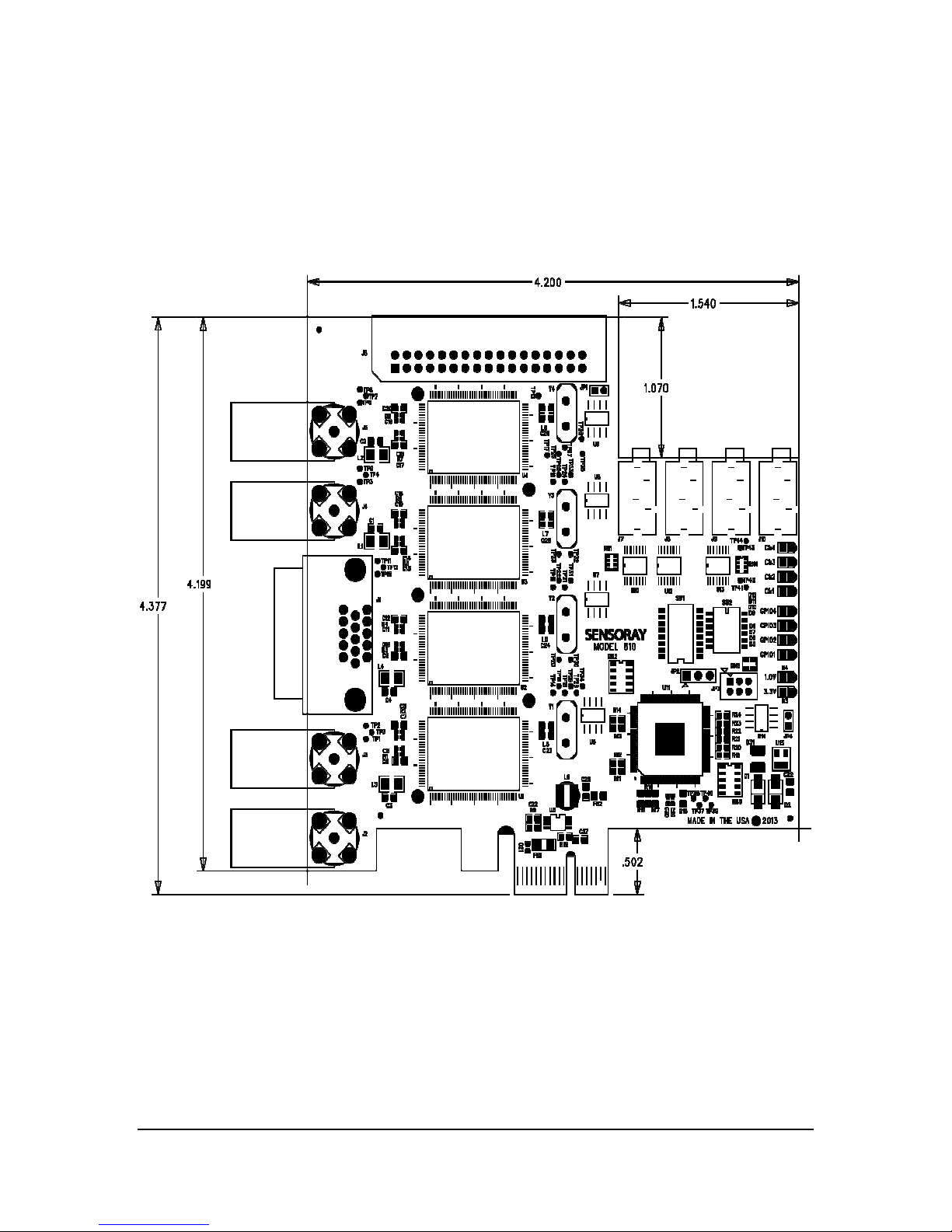
Board Picture and Connector Layout
8
Page 9
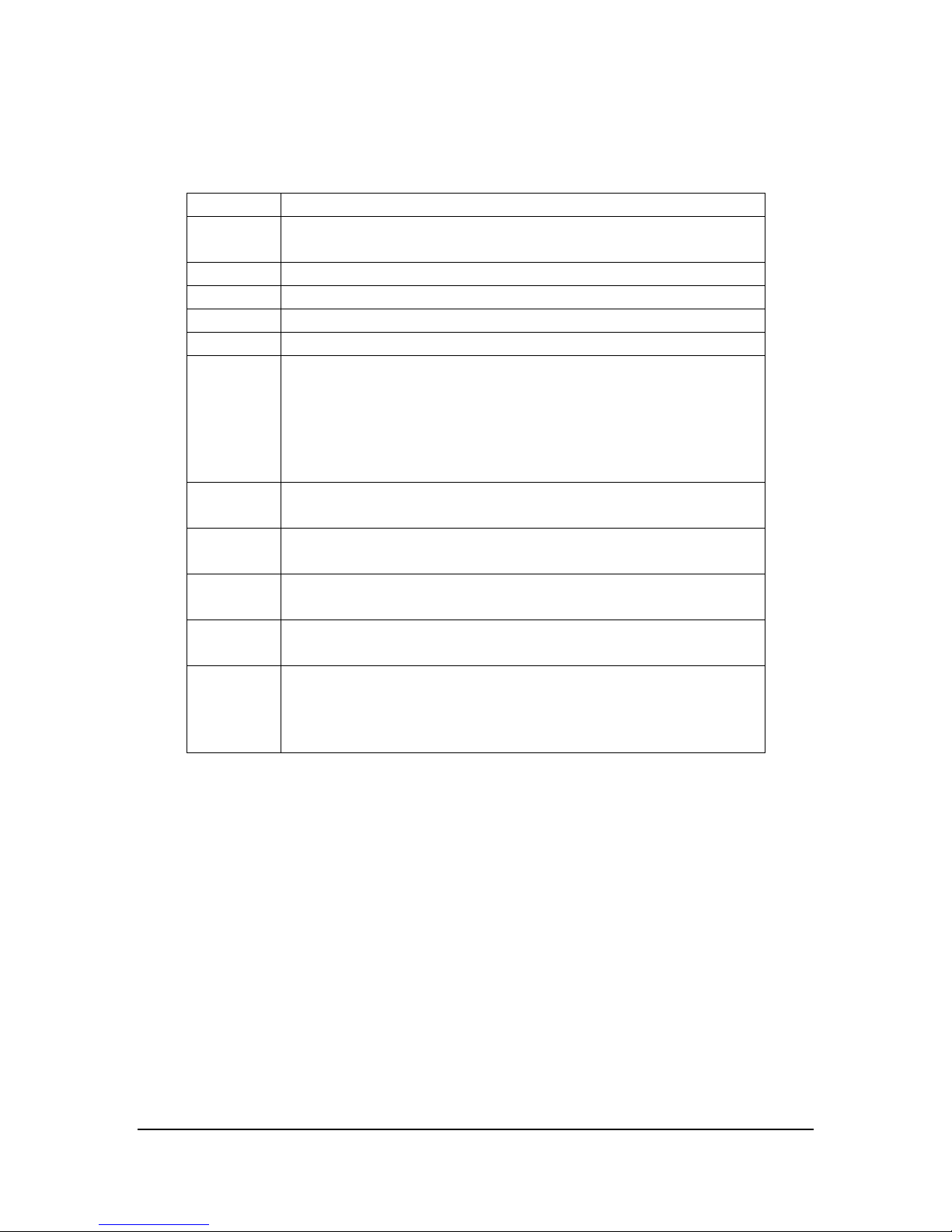
Connector List
P1 PCI-Express Connector
J1 DB-15: Audio Input Breack-in, for all
J2 BNC: Composite Video Input for Channel-1
J3 BNC: Composite Video Input for Channel-2
J4 BNC: Composite Video Input for Channel-3
J5 BNC: Composite Video Input for Channel-4
J6 34-pin Connector:
J7 3.5mm AudioJack: Stereo/Mono Audio Input, Channel-1
J8 3.5mm AudioJack: Stereo/Mono Audio Input, Channel-2
J9 3.5mm AudioJack: Stereo/Mono Audio Input, Channel-3
J10 3.5mm AudioJack: Stereo/Mono Audio Input, Channel-4
JP3 General Purpose Digital I/O: configurable
4 channels of Stereo/Mone, Line-in level
break-in/out for
Composite Video Input for Channel-1, 2, 3, and 4
S-Video Input for Channel-1, 2, 3, and 4
Stereo/Mono Audio Input for Channel-1, 2, 3, & 4
Digital Inputs for Channel-1, 2, 3, and 4
Digital Output for Channel-1, 2, 3, and 4
(optional -- not populated as default)
(optional -- not populated as default)
(optional -- not populated as default)
(optional -- not populated as default)
Digital Inputs for Channel-1, 2, 3, and 4
or
Digital Output for Channel-1, 2, 3, and 4
9
Page 10
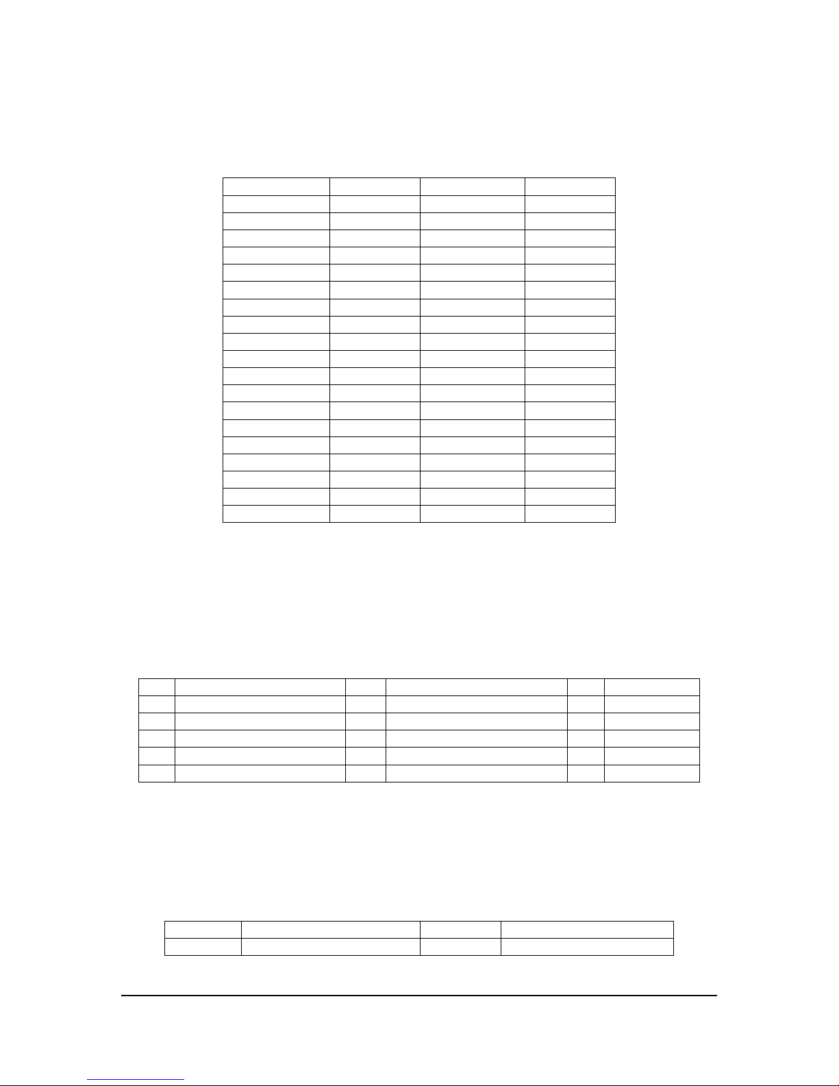
Connector Signal/Pin Definitions
PCI-Express Bus Connector: P1
Pin – Side B Signal Pin – Side A Signal
B1 +12V A1 PRSNT#1
B2 +12V A2 +12V
B3 Reserved * A3 +12V
B4 Ground A4 Ground
B5 SMCLK * A5 TCK
B6 SMDAT * A6 TDI *
B7 Ground A7 TDO*
B8 +3.3V A8 TMS *
B9 TRST# * A9 +3.3V
B10 +3.3VAUX * A10 +3.3V
B11 WAKE# * A11 PWRGOOD
( C-Key ) ( C-Key )
B12 Reserved * A12 Ground
B13 Ground A13 REFCLKP
B14 HSOP0 A14 REFCLKN
B15 HSON0 A15 Ground
B16 Ground A16 HSIP0
B17 PRSNT#2 A17 HSIN0
B18 Ground A18 Ground
Note:
* Not connected.
C-Key Connector Key
Audio Input Connectors, DB15: J1
Pin
1 Audio-In Channel-1 Right 6 Audio-In Channel-4 Right 11 *
2 Audio-In Channel-2 Left 7 Audio-In Channel-4 Left 12 *
3 Audio-In Channel-2 Right 8 GND 13 *
4 Audio-In Channel-3 Left 9 * 14 *
5 Audio-In Channel-3 Right 10 Audio-In Channel-1 Left 15 *
Note:
* Not Used
Signal Pin Signal Pin
Composite Video Input Connector, BNC: J2, J3, J4, and J5
Pin Signal Pin Signal
Inner Composite Video Signal Outer/Ring Shield, Analog ground
10
Signal
Page 11
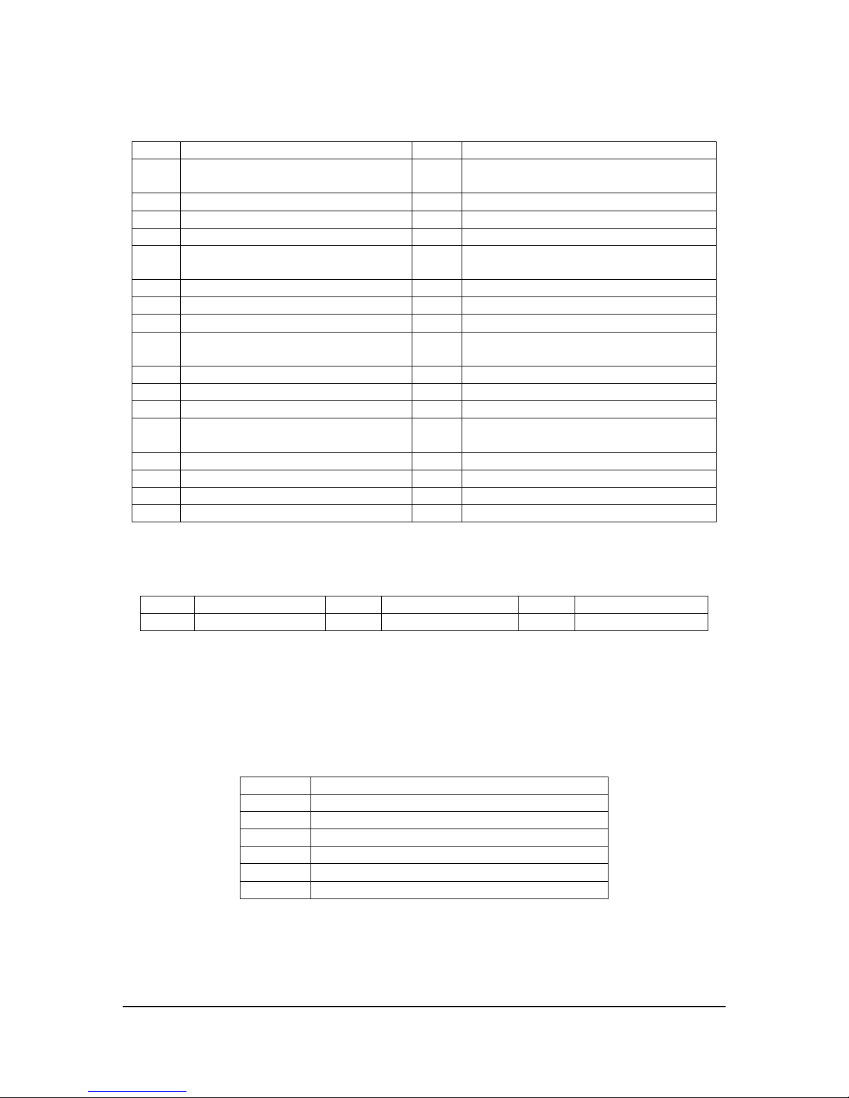
Full A/V (Video & Audio) and Digital I/O Connector: J6
Pin Signal Pin Signal
1 Analog Ground 2 Composite Video In / S-Video In – Y
for Channel-1
3 S-Video In – C for Channel-1 4 Audio In – L for Channel-1
5 Audio In – R for Channel-1 6 Digital Input for Channel-1
7 Digital Output for Channel-1 8 Digital Ground
9 Analog Ground 10 Composite Video In / S-Video In – Y
for Channel-2
11 S-Video In – C for Channel-2 12 Audio In – L for Channel-2
13 Audio In – R for Channel-2 14 Digital Input for Channel-2
15 Digital Output for Channel-2 16 Digital Ground
17 Analog Ground 18 Composite Video In / S-Video In – Y
for Channel-3
19 S-Video In – C for Channel-3 20 Audio In – L for Channel-3
21 Audio In – R for Channel-3 22 Digital Input for Channel-3
23 Digital Output for Channel-3 24 Digital Ground
25 Analog Ground 26 Composite Video In / S-Video In – Y
for Channel-4
27 S-Video In – C for Channel-4 28 Audio In – L for Channel-4
29 Audio In – R for Channel-4 30 Digital Input for Channel-4
31 Digital Output for Channel-4 32 Digital Ground
33 +3.3V 24 Not Used
Stereo Audio Input Connectors, 3.5mm TRS StereoJack: J7, J8, J9, J10
Pin Signal Pin Signal Pin Signal
Tip Stereo Line-in Left Ring Stereo Line-in Right Sleeve Analog ground
Note:
* J7 to J10 are
optional (as default, they are not populated).
Digital I/O Connectors: JP3
Pin Signal
Digital Ground
2 GPIO1 – Digital Input/Output for Channel-1
3 GPIO2 – Digital Input/Output for Channel-2
4 GPIO3 – Digital Input/Output for Channel-3
5 GPIO4 – Digital Input/Output for Channel-4
6 +3.3V
11
Page 12
DIP Switches
Manufacturing DIP Switch: SW1
The DIP switch, SW1, is used for manufacturing only. Therefore, it is not described in
this manual.
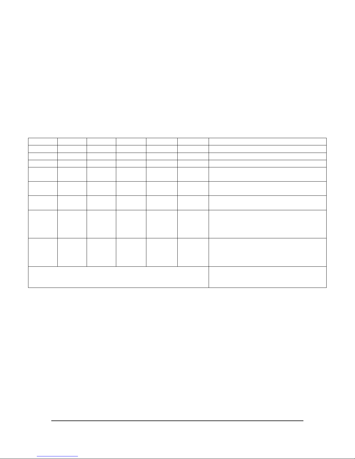
Digital I/O Configuration DIP Switch: SW2
The DIP switch, SW2, is used for configuring Digital I/O routing. Refer to the table
below for the routing details:
SW2-1 SW2-2 SW2-3 SW2-4 SW2-5 SW2-6 Description
OFF X X X X X Disconnect all digital I/O to JP3
X X OFF X X X Disconnect all digital inputs from J6
X X X X OFF X Disconnect all digital outputs to J6
X X ON OFF X X Enable connectivity from J6’s digital input
pins to the board (for all 4 channels)
X X X X ON OFF Enable connectivity from the board to J6’s
digital output pins (for all 4 channels)
X X ON OFF ON OFF Enable connectivity for both digital inputs
& outputs from/to J6 connector
ON ON ON OFF ON OFF Enable connectivity for both digital inputs
& outputs from/to J9 connector;
And, route the digital inputs connected to
the JP3
ON OFF ON OFF ON OFF Enable connectivity for both digital inputs
& outputs from/to J6 connector;
And, route the digital outputs connected to
the JP3
Others
Reserved
12
Page 13
LED
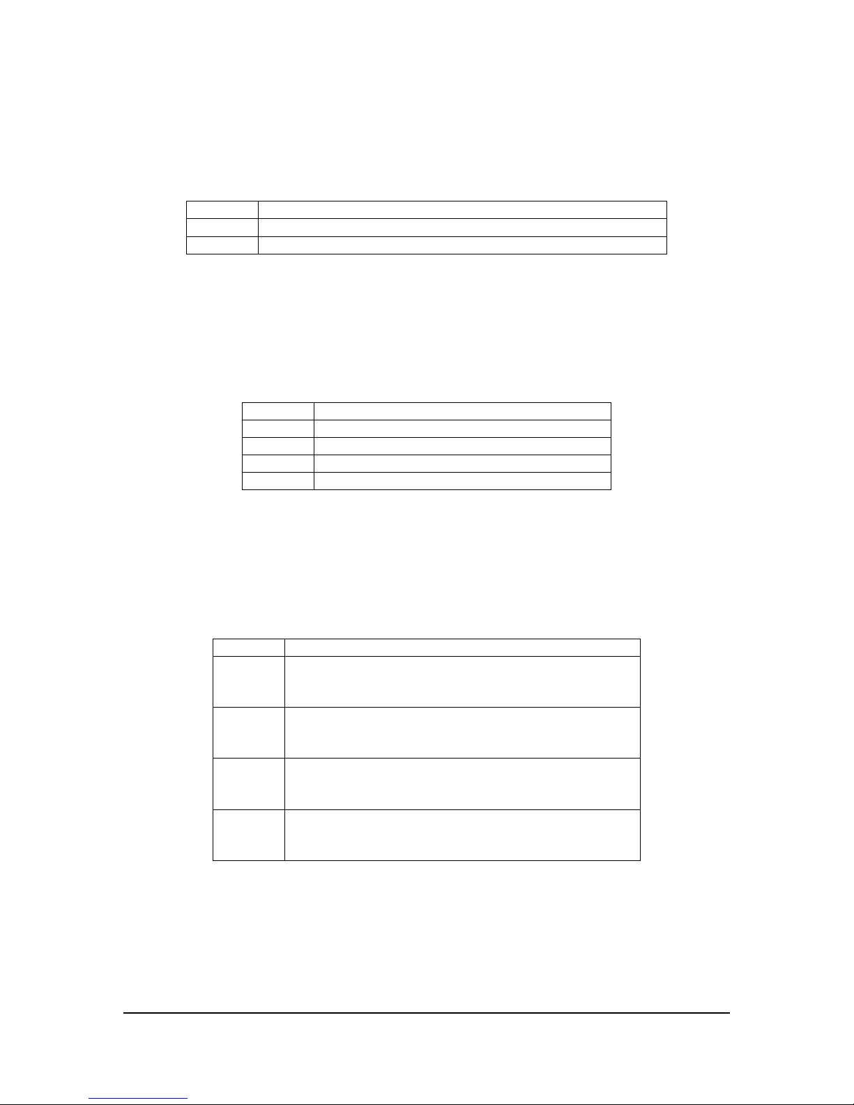
Power-OK indicators: D3 and D4
The LED D3 and D4 are used for indicating on-board Power-OK status.
LED Signal
D3 3.3V Power-OK Status
D4 1.0V Power-OK Status
GPIO Status Indicators: D5 ~ D8:
The LED D5, D6, D7, & D8 are used for indicating the status of the digital input/output
signals (pins), labeled as GPIO1 ~ GPIO4 on the board, and directly connected to the
TB1 ~ TB4. A logic 0 (low) turns the LED on and a logic 1 (high) turns it off.
LED Signal
D5 Status of GPIO1 (associated with Channel-1)
D6 Status of GPIO2 (associated with Channel-2)
D7 Status of GPIO3 (associated with Channel-3)
D8 Status of GPIO4 (associated with Channel-4)
Note:
* The D5 to D8 are
optional (as default, they are not populated).
Channel Status Indicators: D9 ~ D12
The LED D1, D2, D3, and D4 can be used for indicating the channel status, respectively.
LED Signal
D9 Status for Channel-1, the driving signal is connected to
the Channel-1 capturing chipset SAA713xHL’s GPIO15.
A logic low turns the LED on, and a high turns it off
D10 Status for Channel-2, the driving signal is connected to
the Channel-2 capturing chipset SAA713xHL’s GPIO15.
A logic low turns the LED on, and a high turns it off
D11 Status for Channel-3, the driving signal is connected to
the Channel-3 capturing chipset SAA713xHL’s GPIO15.
A logic low turns the LED on, and a high turns it off
D12 Status for Channel-4, the driving signal is connected to
the Channel-4 capturing chipset SAA713xHL’s GPIO15.
A logic low turns the LED on, and a high turns it off
13
Page 14

Software
Device Driver and SDK
Device driver and SDK including driver API & demo application programs are available
for both Windows and Linux.
Windows
Sensoray Co. provides Model 810 WDM driver and DirectX filter for Windows platform.
The SDK includes the Windows driver, DLL, Demo application & source code, etc. It is
packaged in a “s811_v1xx.zip” file for distribution and/or for customer(s) to download
from Sensoray’s website.
Refer to the “Model 811/810 Windows SDK User’s Manual” for the SDK, DLL, API, and
programming details.
Since the driver is built and based on the WDM BDA and DirectShow oriented
architecture, the Microsoft GraphEdit utility can be used for building live A/V preview
and/or capturing application. Also, 3rd party OSS/freeware/shareware like VLC player,
AMCap, MPC (Media Player Classic), and VirtualDub software can be used for still/live
video capturing and/or preview.
Linux
The device driver for Linux is natively provided by kernel.org and comes with most
commonly used or popular Linux distributions. The API complies with standard V4L2
(Video for Linux Version 2), formerly known as V4L (Video for Linux). The API spec and
capturing sample program can be downloaded from following websites:
http://v4l2spec.bytesex.org/
http://www.linuxtv.org/downloads/video4linux/API/V4L2_API/spec-single/v4l2.html
In addition to the application samples from V4L/V4L2, Sensoray Co. provides customized
capturing sample/demo programs and HOW-TO type of app/instruction notes for the
Model 810/811, upon customer’s requests.
For live video preview or capturing, commonly used V4L application programs like
XawTV and TV-Time can be used for capturing/previewing from each channel of the
Model 810/811.
For capturing JPEG frame, MPEG-1/2/4, H.264 or MJPEG video, 3rd party’s or OSS
libraries or CODECs can be used and integrated in the application programs. As a good
example, FFMPEG is a well-know and highly recommended OSS that can be used for the
Model 810/811. Sensoray Co. provides an allocation note on how to use command-line
based FFMPEG to capture A/V (Video or Audio).
14
Page 15
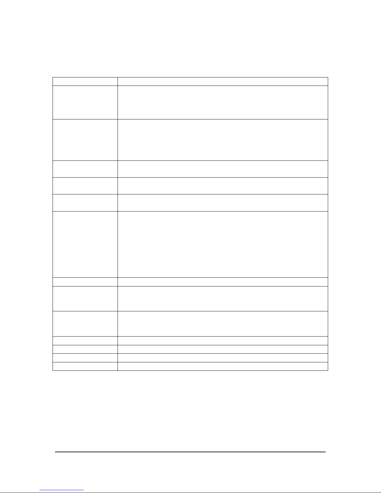
Specifications
Video Formats NTSC, PAL, SECAM
Video Inputs 4 input channels, simultaneously:
4 Composite video via 4 NBC connectors, 75 Ohms; or
4 S-Video via a 34-pin breakout connector, 75 Ohms; or
combinations up to 4 channels , 75 Ohms
Audio Inputs 4 input channels: associated with 4 separated video channels
Stereo or mono for each channel, via four 3.5mm TRS
StereoJacsk;
Or, break-in stereo/mono signal from a 34-pin connector
Signal level: Line-in level, +/- 1.0V
Capturing Mode Raw:
RGB or YUV
Capture Rate Up to: 120 (30x4) frames/sec for NTSC/RS-170/CCIR
100 (25x4) frames/sec for PAL/SECAM
Frame/Video
Encoding
Resolution Up to Full-D1:
VBI Raw VBI decoding, 27Mhz sampling rate
Digital I/O 4 inputs + 4 outputs: TTL signals
Bus PCI-Express x1: Compliant of
OS Platform Windows and Linux
Power 8.25W, +3.3V @ 2.5A
Temperature 0 – 70 C
Board Size 4.2” x 4.37” (107mm x 111mm)
Could be done by software and/or 3rd party CODEC:
JPEG, MPEG-1/2/4, MJPEG, and H.264
NTSC: 720x480 PAL: 720x576
Supported:
D1.N: 720x480 D1.P: 720x576 D.5: 480x352
SIF: 352x240 2SIF: 704x240 4SIF: 704x480
VGA: 640x480 QVGA: 320x240 QQVGA: 160x112
CIF: 352x288 QCIF: 176x144 SQCIF: 128x96
4CIF: 704x576
4 configurable inputs/outputs, via I/O terminals;
all 4 inputs + all 4 outputs on breakout 34-pin connector
PCI-Express Base Specification (Revision 1.0/1.1)
PCI-to-PCI Bridge Specification (Revision1.2)
15
 Loading...