

Page 1

3G-SDI 4x4 Matrix Switch
Model 2444
Hardware Manual
Ver.1.0.2 | May 2014
Page 2

Table of Contents
LIMITED WARRANTY...............................................................................................................3
INTRODUCTION......................................................................................................................4
FRONT PANEL INTERFACE.......................................................................................................5
NETWORK INTERFACE............................................................................................................7
Network setup.....................................................................................................................7
Step 1 – Set up a temporary IP address.............................................................................7
Step 2 – Set up a permanent IP address............................................................................8
HTTP Server........................................................................................................................9
Control page....................................................................................................................9
Switch configuration page...............................................................................................10
Network configuration page............................................................................................11
Information page............................................................................................................12
Telnet server.....................................................................................................................13
Telnet commands...........................................................................................................13
SERIAL COMMUNICATION INTERFACE...................................................................................16
Hardware configuration......................................................................................................16
Software configuration.......................................................................................................17
SPECIFICATIONS..................................................................................................................18
REVISION HISTORY..............................................................................................................19
2
Page 3

Limited warranty
Sensoray Company, Incorporated (Sensoray) warrants the hardware to be free from
defects in material and workmanship and perform to applicable published Sensoray
specifications for two years from the date of shipment to purchaser. Sensoray will, at
its option, repair or replace equipment that proves to be defective during the
warranty period. This warranty includes parts and labor.
The warranty provided herein does not cover equipment subjected to abuse, misuse,
accident, alteration, neglect, or unauthorized repair or installation. Sensoray shall
have the right of final determination as to the existence and cause of defect.
As for items repaired or replaced under warranty, the warranty shall continue in
effect for the remainder of the original warranty period, or for ninety days following
date of shipment by Sensoray of the repaired or replaced part, whichever period is
longer.
A Return Material Authorization (RMA) number must be obtained from the factory
and clearly marked on the outside of the package before any equipment will be
accepted for warranty work. Sensoray will pay the shipping costs of returning to the
owner parts that are covered by warranty. A restocking charge of 25% of the product
purchase price will be charged for returning a product to stock.
Sensoray believes that the information in this manual is accurate. The document has
been carefully reviewed for technical accuracy. In the event that technical or
typographical errors exist, Sensoray reserves the right to make changes to
subsequent editions of this document without prior notice to holders of this edition.
The reader should consult Sensoray if errors are suspected. In no event shall
Sensoray be liable for any damages arising out of or related to this document or the
information contained in it.
EXCEPT AS SPECIFIED HEREIN, SENSORAY MAKES NO WARRANTIES, EXPRESS
OR IMPLIED, AND SPECIFICALLY DISCLAIMS ANY WARRANTY OF
MERCHANTABILITY OR FITNESS FOR A PARTICULAR PURPOSE. CUSTOMER’S
RIGHT TO RECOVER DAMAGES CAUSED BY FAULT OR NEGLIGENCE ON THE
PART OF SENSORAY SHALL BE LIMITED TO THE AMOUNT THERETOFORE PAID
BY THE CUSTOMER. SENSORAY WILL NOT BE LIABLE FOR DAMAGES
RESULTING FROM LOSS OF DATA, PROFITS, USE OF PRODUCTS, OR
INCIDENTAL OR CONSEQUENTIAL DAMAGES, EVEN IF ADVISED OF THE
POSSIBILITY THEREOF.
Third party brands, names and trademarks are the property of their respective owners.
3
Page 4

Introduction
Model 2444 is a 4x4 matrix (crosspoint) switch designed to operate with SDI signals
from 125 Mbps to 2.97 Gbps. It supports SMPTE 259M(C) (SD-SDI), 292M (HD-SDI), and
424M (3G-SDI) serial digital video standards. The switch allows connecting any of the
four inputs to any of the four outputs. Embedded audio is passed along with the video
signal.
Control of the switch is performed with the front panel button interface or using
Ethernet or a serial communications link (RS-422/RS-485). A Web page interface is
available for easy control and configuration of the switch. The same functionality is
available via a simple command line interface over Ethernet (Telnet) or serial
communications link.
LED displays on the front panel provide indication of current connections and input
carrier detect status.
Network settings (IP address, ports) can be changed via the Web page interface to
accommodate various network configurations.
All settings, including the last switch configuration, are stored in non-volatile memory
and restored after power up.
4
Page 5
Front panel interface
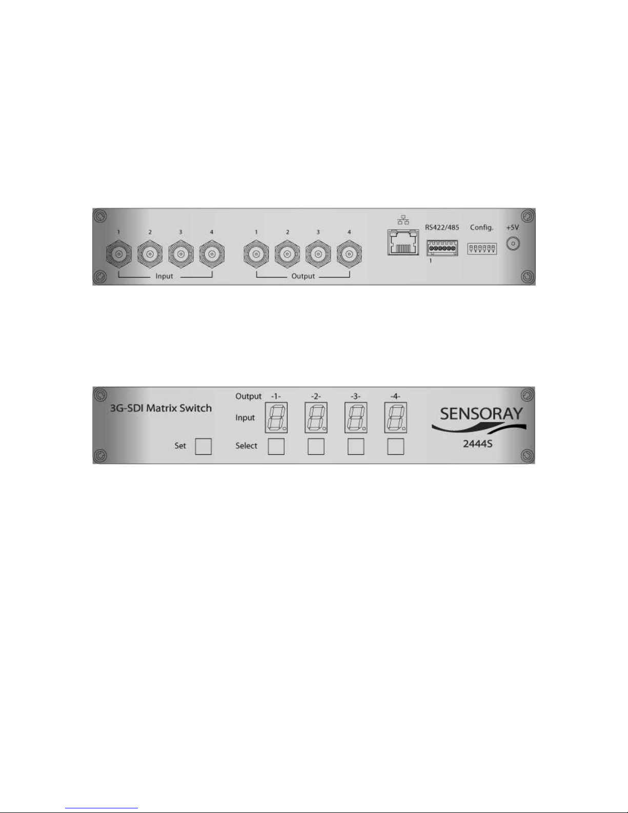
Model 2444 has 4 SDI inputs (numbered 1 through 4) and 4 SDI outputs (numbered 1
through 4). All of those are brought out using BNC connectors on the back panel of the
unit (Fig.1).
Fig.1. Model 2444, back panel.
The front panel interface (Fig.2) consists of 4 seven-segment LED displays and 5 buttons.
Fig.2. Model 2444, front panel.
LED displays reflect the inputs currently connected to the corresponding outputs
(labeled above the displays). The decimal points of the LED displays light up if the
signal is detected at the currently selected input.
Connection for a specific output is changed using the following simple procedure:
1. Press Select button corresponding to the desired output momentarily. The
displayed number increments and starts blinking. Keep pressing the button until
the desired input number is displayed.
2. Press and release Set button. The new settings take effect and the display stops
blinking.
If Set button is not pressed within 5 seconds from the last Select button press, the display
will revert to the previous setting and no changes will be made.
5
Page 6

It is possible to switch more than one output with one press of the Set button. For that
use multiple Select buttons within 5 seconds from the last press.
The brightness of the LED displays can be adjusted via the Web page interface. It is
preserved across power cycles until changed.
6
Page 7

Network Interface
Network setup
Each model 2444 unit is assigned a static IP address. As shipped from the factory the IP
address is set to 192.168.24.44, with the netmask of 255.255.0.0. Those settings,
along with some other, can be modified using a Web page interface. The unit has to be
powered up and connected to the LAN using an Ethernet patch cable, Cat5 or better. If
connecting directly to the computer, use a crossover cable, otherwise use a standard
patch cable.
Depending on the network restrictions one or two steps may be necessary. If the
network used to configure the unit can not access 192.168.x.x IP address range, start
with Step 1, otherwise go directly to Step 2.
Step 1 – Set up a temporary IP address
This step is only necessary if the network used to configure the unit can not access the
default IP address (192.168.24.44). In this case the unit must be switched into the
Configuration Mode which allows setting up a temporary IP address accessible from the
current network. The temporary IP address should be selected such that it is:
1) accessible on the network;
2) is not already used by any other device on the same network.
Once the unit is accessible using a temporary IP address, the standard Web page
procedure (Step 2) can be used to set up the desired permanent IP address and other
settings.
To switch the unit into the Configuration Mode, power it up while holding the Set
button on the front panel pressed. The LEDs will display the word “CONF” and the
front panel buttons will not be functional.
Once the unit is in the Configuration Mode run ARP on the computer that is connected
to the same network with the following command line:
arp -s <temporary_address> 08-00-56-ff-ff-ff
Example:
arp -s 10.135.1.61 08-00-56-ff-ff-ff
In Windows either navigate to Start/Run and type the command line in the “Open” box,
or start a Command Prompt window and type the command line followed by Enter.
In Linux type the command line in the terminal window at the shell prompt followed by
Enter. Please use colon characters (:) instead of dashes (-) in MAC address in Linux.
Note: it is recommended to use a temporary IP address that is different from the target
permanent address to be assigned to the unit.
7
Page 8

Proceed to step 2 without cycling the power (while the unit is still in configuration
mode).
Step 2 – Set up a permanent IP address
Connect to the unit with a Web browser by typing the unit's temporary IP address in the
address box.
Examples:
http://192.168.24.24/network.htm
or
http://10.135.1.61/network.htm
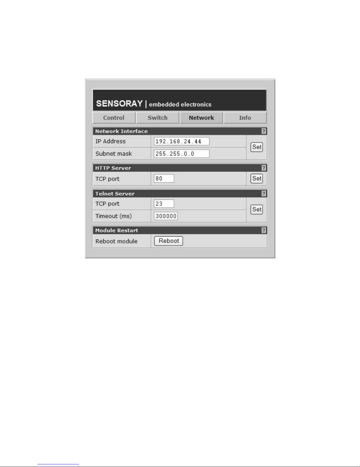
The the network configuration page (Fig.5) will be displayed.
Type in the desired permanent IP address and subnet mask values into corresponding
fields. Click on the Set button and wait for the page to reload. Click on Reboot button.
The unit will reboot with a new IP address, so the current browser session will
disconnect. To continue configuration, type in the new, permanent address in the
address box.
8
Page 9
HTTP Server
The HTTP server (Web page interface) makes it possible to control and configure model
2444 using a computer connected to the network and a browser program.
Control page
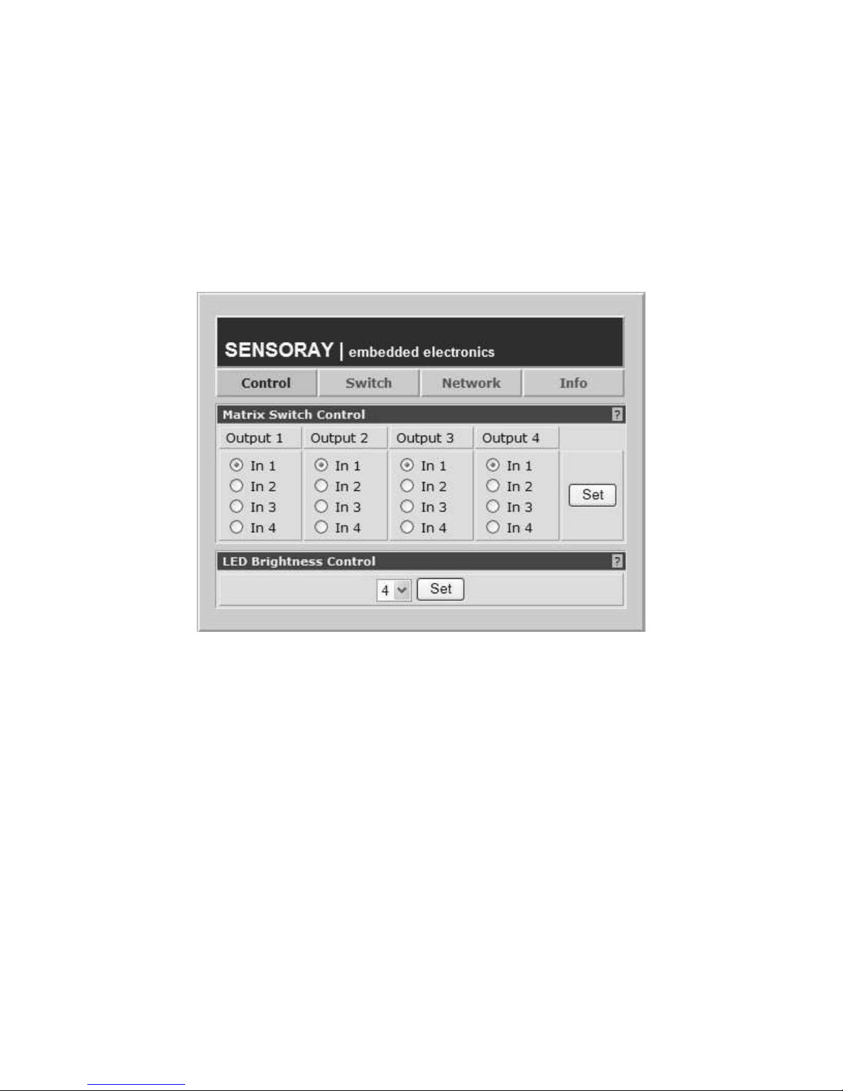
Fig.3. Control page.
Control page allows changing the matrix switch connections and LED brightness.
To change the connections select the desired input for each of the outputs by using radio
buttons and click on the corresponding Set button. The changes in the connections are
immediately reflected on the front panel LEDs.
To change the LED brightness select one of the 8 levels with a list box and click on the
corresponding Set button. The brightness levels vary from 0 (off) to 7 (brightest).
9
Page 10
Switch configuration page
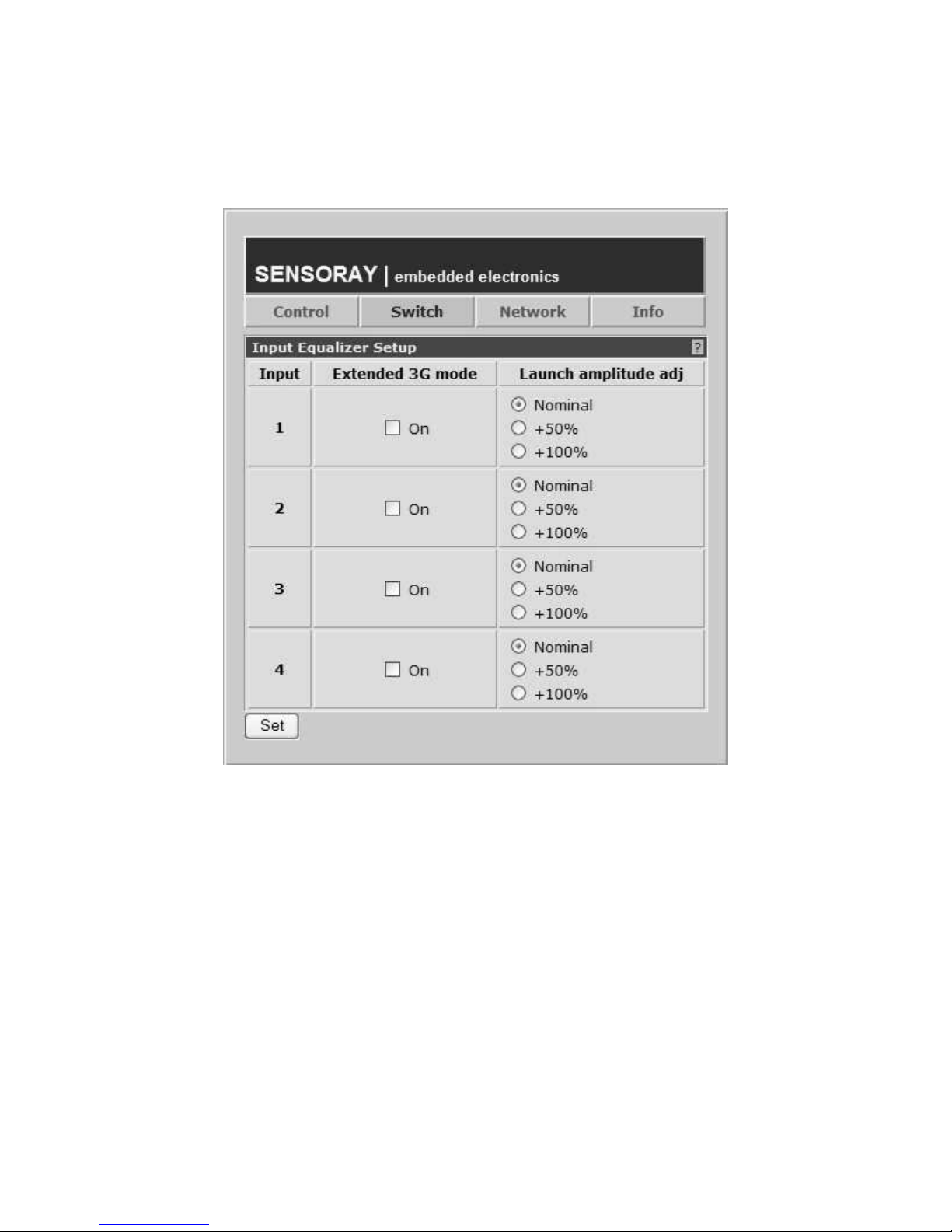
The page allows configuring input equalizers for each of the four inputs of the switch.
Extended 3G mode – turning this mode on (checking the corresponding check box) will
provide extra 10 m of cable reach at 2.97 Gbps. However with this setting on, the cable
reach will be reduced for lower bitrates.
Launch amplitude adjustment – this setting compensates for up to 6 dB signal attenuation
at the input.
Fig.4. Switch configuration page.
10
Page 11
Network configuration page
Fig.5. Network configuration page.
The page provides means to configure network parameters.
Notes:
1. The new parameters do not take effect until the unit is rebooted by clicking on
the Reboot button in the bottom of the page.
2. Certain changes may result in the loss of communication with the unit in the
current browser session. If you have trouble restoring communication because of
some changes that were made, try the following:
a) run ARP with the following command line: arp -d
b) If a) did not help, follow the procedure described in the “Network setup”
section.
3. Do not change ports from their default values unless you are sure it is necessary.
11
Page 12
Information page
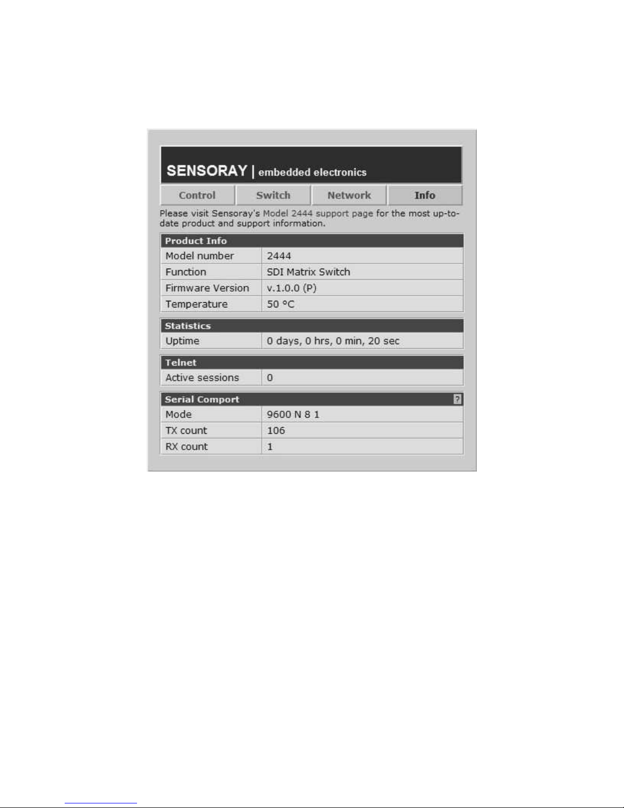
Fig.6. Information page.
The page contains the unit's status information.
12
Page 13

Telnet server
The Telnet server provides an alternative way of controlling the 2244. It may be
particularly useful with automated client applications.
The Telnet server allows 2 sessions: one through Ethernet port, and one through the
serial port. Although the sessions are independent, it is not recommended to use both
simultaneously.
Telnet commands
Below is the list of telnet commands supported by the 2444.
help
Syntax:
help
lists all available commands;
help <command>
shows command syntax details.
quit
Syntax:
quit
terminates current telnet session.
ver
Syntax:
ver
displays current firmware version.
wto
Syntax:
wto <value> <units>
Set the telnet session timeout value.
<value> - 0 <timeout disabled> to N (<= 3600 s);
<units> - ms (milliseconds) or s (seconds);
13
Page 14

ssw
Syntax:
ssw <out> <in>
Connect matrix switch output out (1-4) to input in (1-4).
gsw
Syntax:
gsw <out>
Get the input connected to output out (1-4). Returns 1-4.
gcd
Syntax:
gcd <in>
Get carrier detection status for input in. Returns 1 for carrier detected, 0
otherwise.
sx3g
Syntax:
sx3g <in> <val>
Set extended 3G mode for input in (1-4) to on (val = 1) or off(val = 0).
gx3g
Syntax:
gx3g <in>
Get extended 3G mode for input in (1-4). Returns 1 (on), or 0 (off).
sla
Syntax:
sla <in> <val>
Set launch amplitude for selected input in (1-4) to one of the following values
(val): 0 – default, 1 - +50%, 2 - +100%.
14
Page 15

gla
Syntax:
gla <in>
Get launch amplitude value for selected input in. Returns 0 (default), 1 (+50%)
or 2 (+100%).
sbri
Syntax:
sbri <val>
Sets the front panel LED brightness to value val (0-7), with 0 being off, 7 being
the brightest.
gbri
Syntax:
gbri
Gets LED display brightness value (0-7).
cls
Syntax:
cls
Clears terminal screen.
15
Page 16

Serial communication interface
Model 2444 supports serial communication interface configurable as RS-422 or RS-485.
The interface is connected to external device(s) via a 6-pin terminal block (Table 1). A
mating connector is provided with every unit.
The serial interface supports the set of commands identical to that of the Ethernet telnet
server. It is possible to communicate to the 2444 using a terminal program (for example,
Hyperterminal in Windows). To achieve the look and feel similar to that of a telnet
session it is recommended to configure the terminal program to add LF (Line Feed)
characters to CR (Carriage Return) characters and to echo input characters. For example,
in Hyperterminal select “File/Properties” from the menu, select the “Settings” tab, click
on “ASCII setup”, and check “send line ends with line feeds” and “echo typed
characters locally”.
Hardware configuration
The serial communication interface is configured with a set of DIP-switches labeled
“Config.”), accessible from the back panel of the 2444 (Fig.1). The functions of the
switches are described in Table 2. The “On” position of the switch corresponds to the
lever pushed down. The default position of switches 1-5 as shipped from the factory is
“Off”, switch 6 - “On”.
Table 1. Serial communication interface pinout.
Pin Signal Function
1 RX+ Receive, active high
2 RX- Receive, active low
3 GND Signal reference (ground)
4 TX- Transmit, active low
5 TX+ Transmit, active high
6 GND Signal reference (ground)
16
Page 17

Table 2. Configuration switches.
Switch Function
1 Off Output driver 120 Ohm termination off
On Output driver 120 Ohm termination on
2 Off Input driver 120 Ohm termination off
On Input driver 120 Ohm termination on
3 Off RS-422
On RS-485
4 Off RS-422
On RS-485
5 Reserved Must be in “Off” position.
6 Reserved Must be in “On” position.
Note. Switches 3 and 4 must be either both “Off” (RS-422), or both “On” (RS-485).
Software configuration
The serial communication interface operates with the following settings:
• baud rate – 9600;
• data bits – 8;
• stop bits – 1;
• parity – none.
17
Page 18
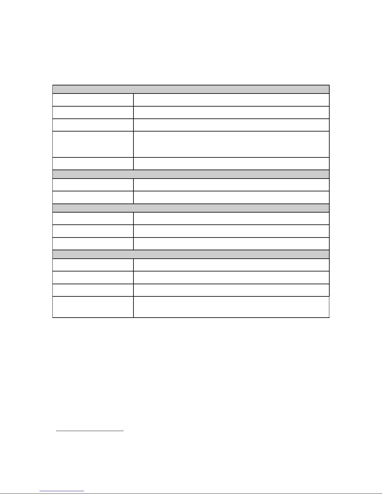
Specifications
Video
Matrix 4x4 (4 inputs, 4 outputs)
Supported data rates 270 Mbps, 1.483 Gbps, 1.485 Gbps, 2.967 Gbps, 2.97 Gbps
Standards SMPTE 259M(C), SMPTE 292M, SMPTE 424M
Input equalization
Impedance 75 Ohm, input and output
Ethernet Interface
Data rates 10Base-T, 100Base-TX
Protocols HTTP (Web page), Telnet
Serial Interface
Operating mode 9600 baud, no parity, 8 data bits, 1 stop bit
Physical layer RS-422, RS-485
Protocol Telnet
Mechanical, electrical, environmental
Dimensions 10.0 (W) x 1.72 (H) x 4.4 (L) in
1
100 meters (2.97 Gbps)
200 meters (1.48 Gbps)
400 meters (270 Mbps)
Weight 600 g
Power, max 7.5 W (5 V DC)
Operating ambient
0-50 ºC
temperature
1
With Belden 1694A cable.
18
Page 19

Revision history
Version Notes
1.0.2, May 2014 Correction in the IP address setup procedure with a Linux
computer.
1.0.1, May 2011 Equalized cable length specifications and embedded audio
added. Power specification updated.
1.0.0, January 2011 Initial release.
19
 Loading...