

Page 1
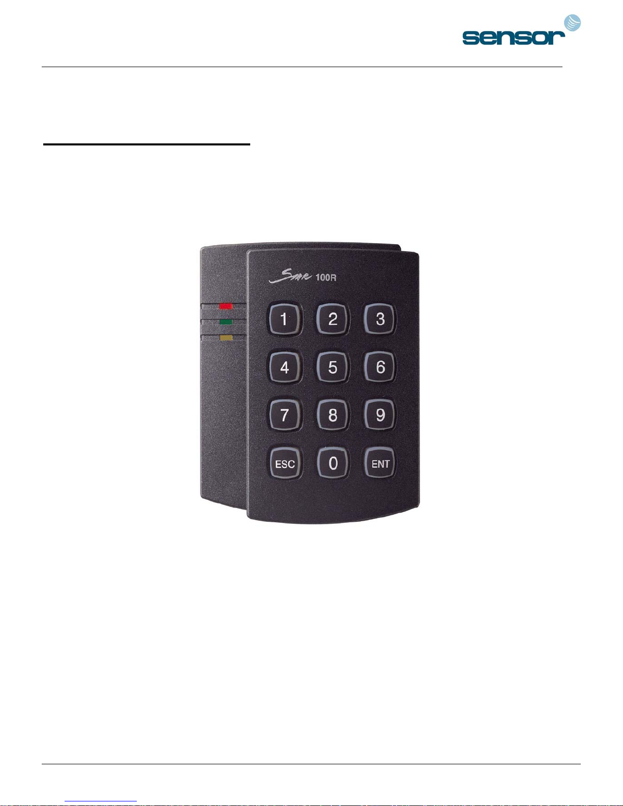
SENSORPROX 100R/PIN120 -
SINGLE DOOR CONTROLLER
USER MANUAL
1
Page 2

SENSORPROX 100R/PIN120 -
TABLE OF CONTENTS
SINGLE DOOR CONTROLLER
1. Important Safety Instructions 3
2. General 3
3. Features 4
4. Specification 4
5. Front Panel Description 5
6. Identifying Supplied Parts 5
7. Installation of the Product 6
8. Color Coded & Wiring Table 7
9. System Wiring for Typical Application 8
10. Initial Setup 11
11. Operation 13
12. Setting Changes 14
13. FCC Registration Information 25
15. Template 26
2
Page 3

SENSORPROX 100R/PIN120 -
SINGLE DOOR CONTROLLER
1. IMPORTANT SAFETY INSTRUCTIONS
When using your Single Door Controller, basic safety precautions should always be followed to reduce the risk of fire, electrical
shock, and injury to persons. In addition, the following should also be followed:
1. Read and understand all instructions.
2. Follow all warnings and instructions marked on the product.
3. Do not use liquid cleaners or aerosol cleaners. Use a damp cloth for cleaning. If necessary, use mild soap.
4. Do not use this product near water, such as bath-tub, wash bowl, kitchen sink, laundry tub, in a wet basement, or swimming pool.
5. This product should be operated only from the type of power source indicated on the marking label. If you are not sure of the
type of power supplied to your installation site, consult your dealer or local power company.
6. Never push objects of any kind into this product or through the cabinet slots as they may touch voltage points or short out parts
that could result in fire or electric shock. Never spill liquid of any kind on the product.
7. To reduce the risk of electric shock, do not disassemble this product by yourself, but take it to qualified service whenever service
or repair is required. Opening or removing the covers may expose you to dangerous voltages or other risks. Also, incorrect
reassembly can cause electric shock when the unit is subsequently used.
8. Unplug this product from the Direct Current (DC) power source and refer to qualified service personnel under these conditions:
a. When the power supply cord or plug is damaged or frayed.
b. If liquid has been spilled on the product.
c. If the product does not operate normally after following the operating instructions in this manual.
Adjust only those controls that are covered by the operating instructions in this manual. Improper adjustment of other controls
that are not covered by this manual may damage the unit and will often require extensive work by a qualified technician to
restore normal operation.
d. If the product exhibits a distinct change in performance.
2. GENERAL
A properly configured SENSORPROX 100R/PIN120 is an intelligent single door controller that combines the convenience of wireless
entry with the security of an alarm system. Also, the SENSORPROX 100R/PIN120 system will give you field proven reliability and
cost-effective solution anywhere access controls and high security are required. Each standard unit can store up to 512 users or card
Ids. The task of assigning cards and managing a user’s database is so simple, user friendly, and can be accomplished in many
ways; it could be as simple as presenting each card to the unit or as descriptive as a user’s database with an easy to use Graphical
User Interface.
The SENSORPROX 100R/PIN120 can interface and operate with these accessories: Request for EXIT button, Door-Contact sensor, PIR
sensor, Fire sensor and other sensors via 5 independent input ports. Also, output ports which include 2 Relays and 2 TTL outputs can
be used to control the operation of other accessories such as Electric/Magnetic Door Lock, Alarm, Chime Bell, and Auto-Dialer.
Moreover, the status or behaviors of these input and output accessories are configurable to provide the system administrator with
complete customized control of the system. Besides the above configurable I/O interfaced behaviors, many of the SENSORPROX
100R/PIN120 internal behaviors are programmable as well.
The internal operating parameters include the number of incorrect access attempts before alarm condition is triggered, tampering
protection from mounting removal, and timers. Furthermore, every event or transaction can be captured and time stamped by the
SENSORPROX 100R/PIN120 application software via the provided RS-232 wires.
3
Page 4

SENSORPROX 100R/PIN120 -
SINGLE DOOR CONTROLLER
3. FEATURES
- Single Door Controller
- Built-in Proximity Reader with up to 10cm read range with IDC170 card
- 512 Users or Card IDs including the Configuration card
- 5 independent input ports
- 4 output ports including 2 Form-C Relays to facilitate either Power-Failed Safe or Secure mode of operation
- All I/Os behaviors and associated Timers are user programmable either through the keypad or the application software
- Door Lock and Unlock functions
- Configurable for Normal/Secure mode of operation (Secure Mode requires using external sensor(s) and alarm/siren)
- Covert Duress sensing and responding (activate a silent alarm through the external Auto-Dialer)
- Programmable On/Off audio feedback (turning off audio feedback for Silent mode of operation)
- Programmable the maximum number of unsuccessful attempts allow before activating the Alarm when exhaustive break-in method
is employed
- RS-232 communication port for interfacing with the SENSORPROX 100R/PIN120 application software
- 3 LEDs (red, green, and yellow) for system operation status
- Chime Bell function to operate an externally connected Doorbell
4. SPECIFICATION
.Memory : Flash, Non-volatile, 1 millions times read/write
.Power : DC 12V/ 200mA max.
.Proximity reader : Built-in Proximity reader with up to 10cm read range with IDC170
card
.User capacity : 512 Users including the Configuration card
.Input/Output : 5 Inputs, max. rating at DC12V/20mA
: 2 Relay outputs : DC12V~24V/2A max.
: 1 chime bell output : DC5V/150mA max.
: 1 TTL output : DC5V/20mA
.Communication : One RS-232 port, 9600 Baud Rate,N,8,1, Xon and Xoff
.Keypad : 12 Numeric Keypad
.LED : 3 LEDs (red, green, and yellow)
.Operating environment range : -35°C to +65°C, 10% to 90% Humidity
.Storage environment range : -40°C to +70°C, 10% to 90% Humidity
.Mounting : Wall mounted and US or European gang box
.Weight : 0.464lbs (210gm)
.Dimensions : 4.17” x 3.40” x 1.22”
.Color : Dark pearl grey
.Material : Polycarbonate
.Format : 26-bit Wiegand
.Certification : UL-294 indoor and outdoor compliance, FCC Class A part 15 and CE
4
Page 5
SENSORPROX 100R/PIN120 -
SINGLE DOOR CONTROLLER
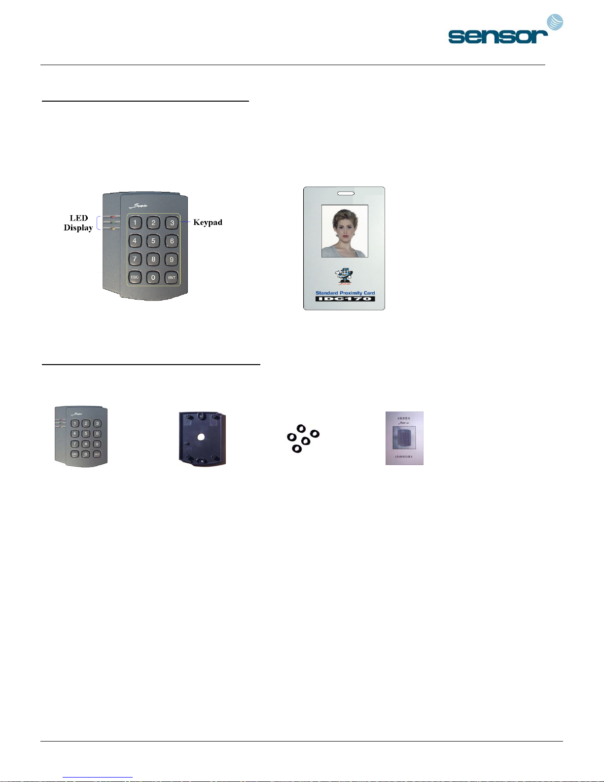
5. FRONT PANEL DESCRIPTION
SENSORPROX 100R/PIN120
Main Unit
6. IDENTIFYING SUPPLIED PARTS
Please unpack and check the contents of the box.
MainUnit Wall Mount O-Ring Manual
(1 EA) (1 EA) (5 EA) (1 EA)
5
Page 6
SENSORPROX 100R/PIN120 -
SINGLE DOOR CONTROLLER
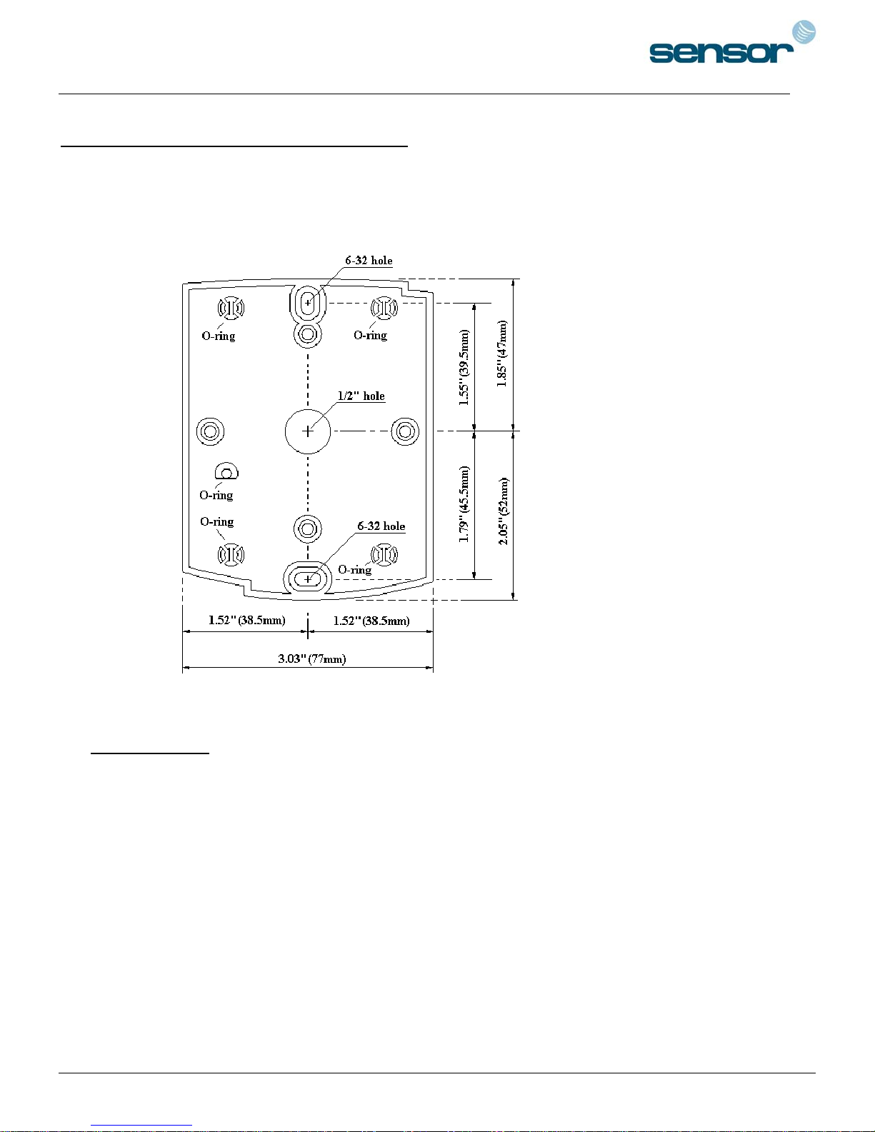
7. INSTALLATION OF THE PRODUCT
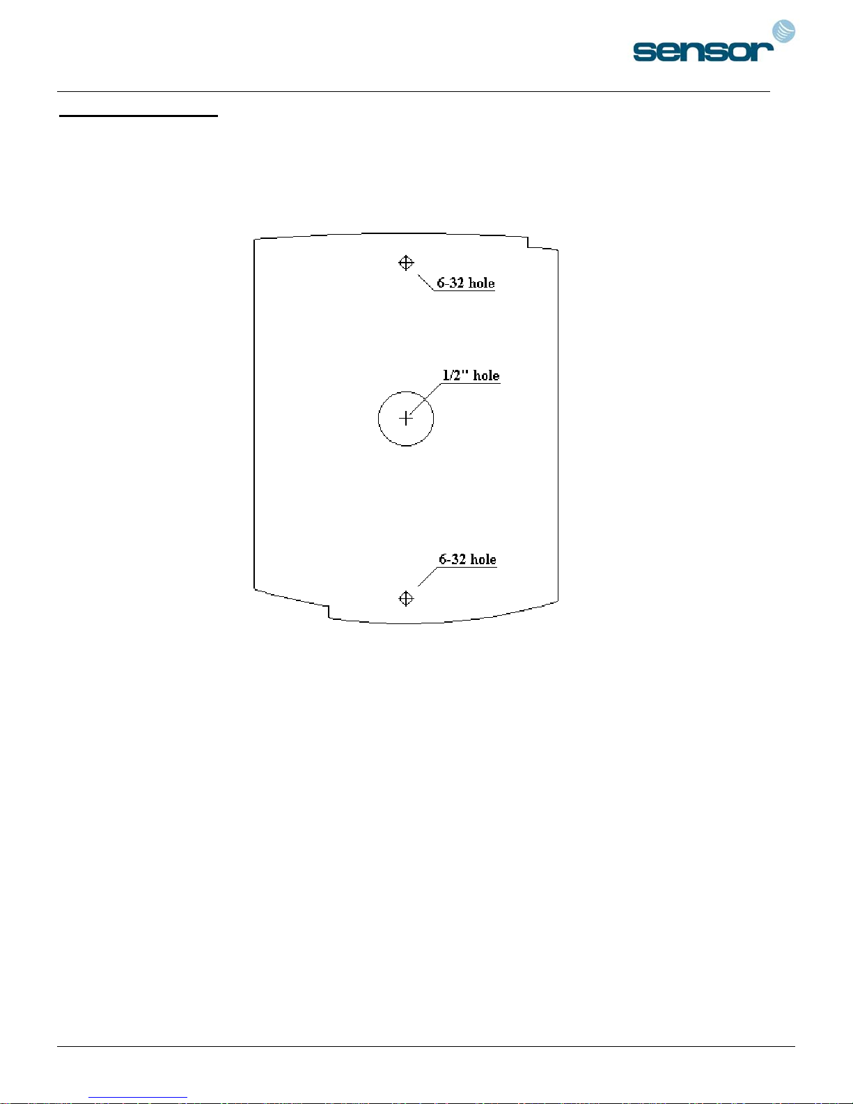
. Tear off page 27 and use the provided template to drill two 6-32 holes and one 1/2" hole on the
7-1
proper location of the wall to mount the Wall Mount bracket as shown below.
(If the gang box is already installed on the wall then skip this step.)
Using 2 screws, install wall mount to the wall.
7-2.
* CAUTIONS *
Before mounting the SENSORPROX 100R/PIN120 unit to the Wall Mount bracket, operational testing
of the unit should be completed, as the locking pins will lock the unit to the Wall Mount. Removing the
unit from the Wall Mount bracket after they have been installed together may cause damages to the
bracket and render its effectiveness.
. Insert 5 O-rings to the wall mount as indicated, then route the cable of the main unit through the center
7-3
hole and push the main unit to wall mount to lock the main unit and make sure that the main unit is locked
with wall mount.
6
Page 7

SENSORPROX 100R/PIN120 -
SINGLE DOOR CONTROLLER
8. COLOR CODED & WIRING TABLE
I/O PORT NAME SIGNAL NAME COLOR CODED
POWER
Main Power (V+) +12V Red wire & Red with White band
Power Ground 0V Black wire & Black with White band
OUTPUT
Door RELAY(2A) COM Grey wire with Red band
Door RELAY(2A) NC Blue wire with White band
Door RELAY(2A) NO White wire with Red band
Alarm RELAY(2A) COM White wire
Alarm RELAY(2A) NC Purple wire with White band
Alarm RELAY(2A) NO Purple wire
TTL Output TTL Orange wire with White band
CHIME BELL Output BELL Brown wire with White band
INPUT
Exit Button EXIT Yellow wire with Red band
Door Sensor CONTACT Green wire
Aux Input #1 IN#1 Orange wire
Aux Input #2 IN#2 Green wire with White band
Aux Input #3 IN#3 Brown wire
WIEGAND INPUT / OUTPUT
Wiegand Data 0 DATA0 Pink wire
Wiegand Data 1 DATA1 Cyan wire
RS232 INTERFACE
RS232-TX TXD Grey wire
RS232-RX RXD Blue wire
RS232-GND GND Yellow wire
7
Page 8
SENSORPROX 100R/PIN120 -
SINGLE DOOR CONTROLLER
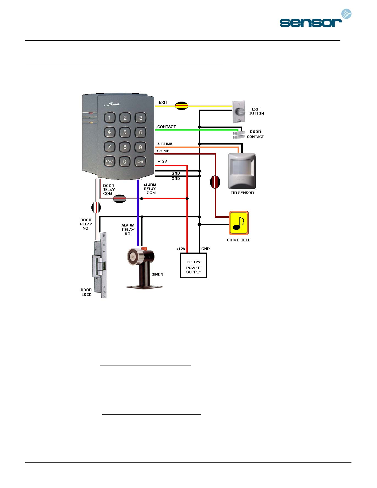
9. SYSTEM WIRING FOR TYPICAL APPLICATION
. Power Connection
9-1
- Connect (+) wire of DC +12V power to Red wire and Red/White banded wire.
- Connect Power GND (-) wire of DC +12V to Black wire and Black/White banded wire.
. Door Lock Connection
9-2
9-2-1 Connection of POWER FAIL SAFE: Door Lock
- Connect Door RELAY (NC), Blue/White banded wire to DC +12V (be sure that the existing power
supply has enough capacity to support this accessory or upgrade to a sufficient one.)
- Connect (+) wire of Door Lock to Door RELAY (COM), Grey/Red banded wire.
- Connect (-) wire of Door Lock to Power GND (-) wire.
9-2-2 Connection of POWER FAIL SECURE: Door Lock
- Connect Door RELAY (COM), Grey/Red banded wire to DC +12V (be sure that the existing power
supply has enough capacity to support this accessory or upgrade to a sufficient one.)
- Connect (+) wire of Door Lock to Door RELAY (NO), White/Red banded wire.
- Connect (-) wire of Door Lock to Power GND (-) wire.
8
Page 9
SENSORPROX 100R/PIN120 -
SINGLE DOOR CONTROLLER
. Alarm Device Connection
9-3
- Connect Alarm RELAY (COM), White wire to DC +12V (be sure that the existing power supply has
enough capacity to support this accessory or upgrade to a sufficient one.)
- Connect (+) wire of Alarm Device to Alarm RELAY (NO), Purple wire.
- Connect (-) wire of Alarm Device to Power GND (-) wire.
. Exit Button Connection
9-4
- Connect one of the wires of Exit Button to Exit Button Input, Yellow/Red banded wire.
- Connect the other wire of Exit Button to Power GND (-) wire.
(If a normally closed Exit button is used, then see section 12-67 to change the detection scheme from the
defaulted setting)
. Door Contact Sensor Connection
9-5
- Connect Door Contact sensor (COM) wire to Door Contact Input, Green wire.
- Connect Door Contact sensor (NO) wire to Power GND (-) wire.
(If a normally closed Door Contact sensor is used, then see section 12-69 to change the detection scheme
from the defaulted setting.)
. Auxiliary Input Device Connection (Applied to AUX Input #1, #2, #3)
9-6
- Connect one wire of the Auxiliary Input Device to the AUX Input wire
(Input #1 Orange, Input #2 Green/White banded, Input #3 Brown wire).
- Connect the other wire of Auxiliary Input Device to Power GND (-) wire.
(If a normally closed input device is used, then see section 12-61,63 & 65 to change the detection
schemes from the defaulted settings.)
. Auto-Dialer Connection (Separate purchase required)
9-7
The Auto-dialer function of this unit has not been evaluated by UL.
- Connect the input wire of Auto-Dialer to TTL output, Orange/White banded wire.
- Connect (+) wire of Auto-Dialer to DC +12V (be sure that the existing power supply has enough
capacity to support this accessory or upgrade to a sufficient one.)
- Connect (-) wire of Auto-Dialer to Power GND (-) wire.
- Connect Telephone Line plug (RJ-14) to Auto-Dialer.
(If an active High Auto-Dialer is used, then see section 12-71 to change the TTL output level from the
defaulted setting.)
9
Page 10

SENSORPROX 100R/PIN120 -
. Wiegand Input Connection From Another Compatible Wiegand Reader
9-8
SINGLE DOOR CONTROLLER
(Separate purchase required)
- Connect (+) wire of Reader to DC +12V (be sure that the existing power supply has enough capacity
to support this accessory or upgrade to a sufficient one.)
- Connect (-) wire of Reader to Power GND (-) wire.
- Connect Wiegand output DATA0 wire of the additional Reader to DATA0, Pink wire.
- Connect Wiegand output DATA1 wire of the additional Reader to DATA1, Cyan wire.
9-9. RS-232 Communication Port Connection
9-pin connector (COM Port, female) is required to connect serial communication RS-232 between Main Unit
and Personal Computer.
- Connect RS-232-TX, Grey wire of Main Unit to pin number 2 of 9-pin connector.
- Connect RS-232-RX, Blue wire of Main Unit to pin number 3 of 9-pin connector.
- Connect RS-232-GND, Yellow wire of Main Unit to pin number 5 of 9-pin connector.
- Plug in 9-pin connector to COM1 or COM2 Port of Personal Computer.
- Install and run SENSORPROX 100R/PIN120 Application Software.
9-10. Chime Bell Connection (Separate purchase required)
- Connect (+) wire of Chime Bell unit to Bell Output, Brown/White wire of Main Unit.
- Connect (-) wire of Chime Bell unit to Power GND (-) wire.
10
Page 11
SENSORPROX 100R/PIN120 -
10. INITIAL SETUP
SINGLE DOOR CONTROLLER
The Flash memory of each shipped STAR 100R/PIN120 contains a minimum set of defaulted values, but it
does not have any other preprogrammed values or user’s data in it, therefore, Initial Setup is required upon
the first time the unit is powered-up in order to operate the unit properly.
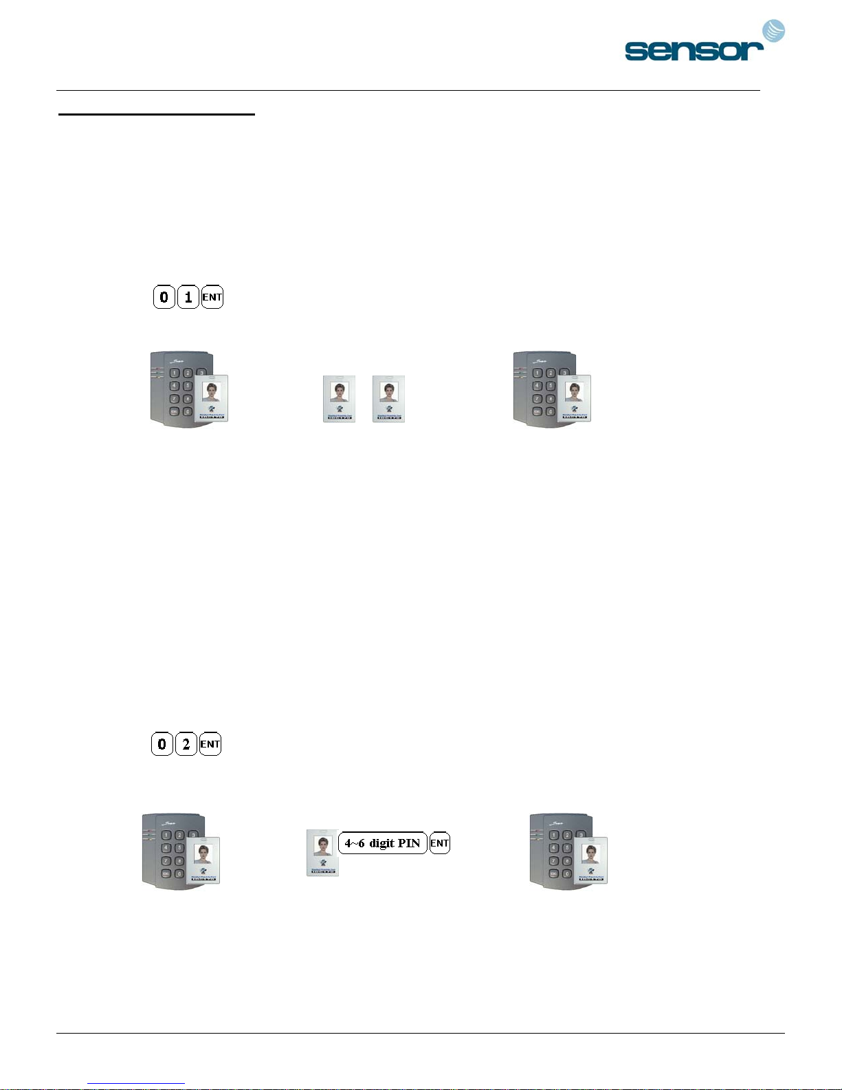
10-1. Registration of RF Cards for RF CARD ONLY MODE
(1) Apply 12VDC to the unit.
All 3 LEDs will be flashing along with a powered-up melody (do mi sol me do..do mi sol do~).
(2) Press from the keypad. (RF CARD ONLY MODE )
(3) Present RF Cards as follow to register Configuration Card and User Access Cards.
........
Configuration Card User Access Cards Configuration Card again to end task.
NOTE: The user may choose to register the 8 digit card numbers via the keypad instead of
presenting the cards to the unit; this implies that the user must know the 8 digit
representation of each card.
(4) The first card read becomes the Configuration Card and the following RF Cards are registered as
User Access Cards. Once all User Access Cards have been registered, present the Configuration Card
again to complete the registration. (Please keep the Configuration Card in a secure location for future
changes.)
(5) Now, the Main Unit is entered into the normal operation mode with factory defaulted settings.
10-2. Registration of RF Cards with PINs for RF CARD + PIN MODE
(1) Apply 12VDC to the unit.
All 3 LEDs will be flashing along with a powered-up melody (do mi sol me do..do mi sol do~).
(2) Press from the keypad. (RF CARD + PIN MODE )
(3) Present RF Cards as follow to register Configuration Card and User Access Cards + 4~6 digit
Personal Identification Number (PIN) for each User Access Card.
........
Configuration Card User Access Cards + PINs Configuration Card again to end task.
(4) The first card read becomes the Configuration Card and the following RF Cards + PINs are registered
as User Access Cards with assigned PINs. Once all User Access Cards and PINs have been registered,
present the Configuration Card again to complete the registration. (Please keep the Configuration
Card in a secure location for future changes.)
11
Page 12
SENSORPROX 100R/PIN120 -
SINGLE DOOR CONTROLLER
(5) Now, the Main Unit is entered into the normal operation mode with factory defaulted settings.
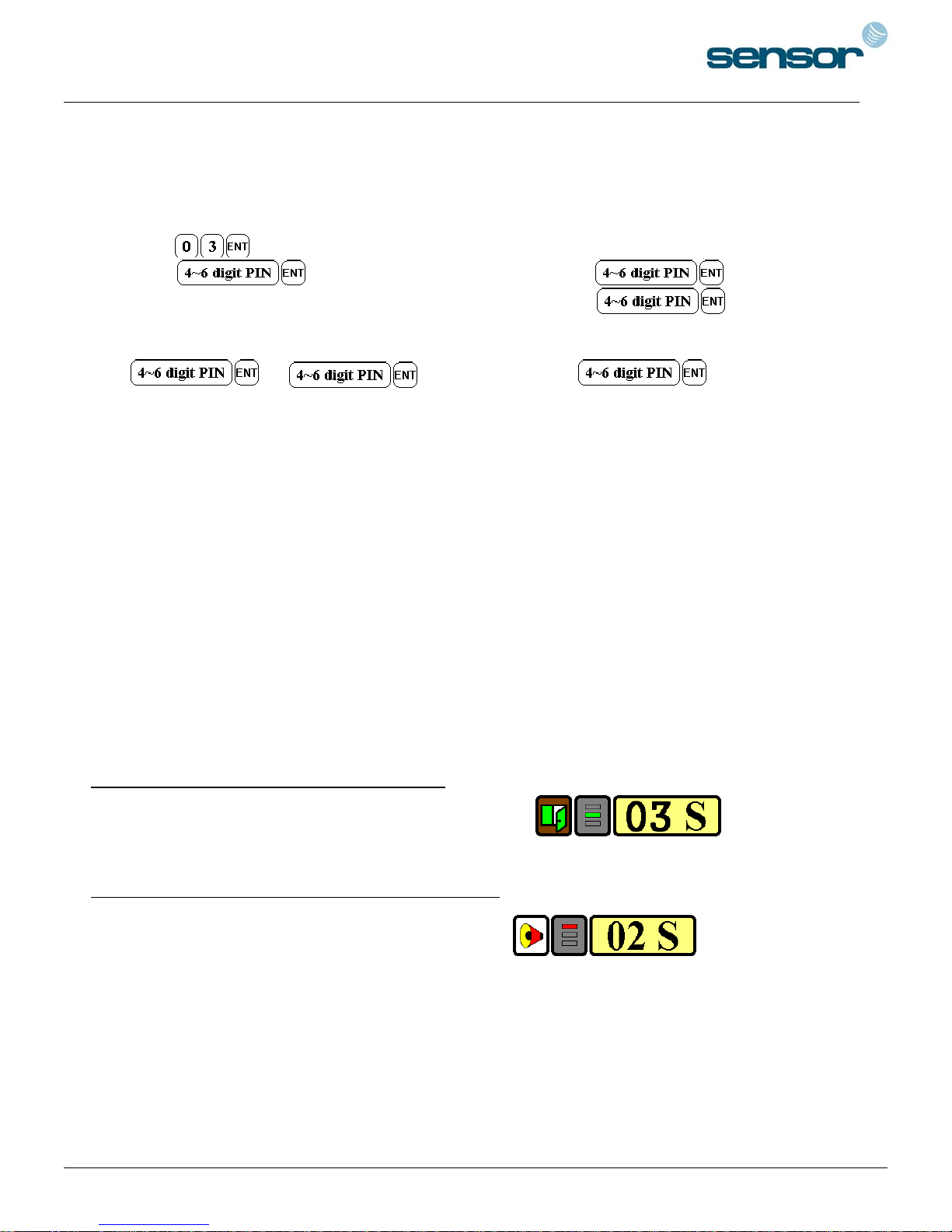
10-3. Registration of PIN ONLY MODE
(1) Apply 12VDC to the unit.
All 3 LEDs will be flashing along with a powered-up melody (do mi sol me do..do mi sol do~).
(2) Press from the keypad. (PIN ONLY MODE)
(3) Enter to register Configuration PIN then to register for
each subsequent User Access PIN at a time and then enter the
(Configuration PIN) to complete the registration.
……..
Configuration PIN User Access PIN... Configuration PIN again
to complete the registration.
(4) The first 4~6 digit PIN becomes the Configuration PIN and the subsequent 4~6 digit PINs are
registered as User Access PINs. Once all User Access PINs have been registered, enter the
Configuration PIN again to complete the registration. (Please store the Configuration PIN for future
changes.)
(5) Now, the Main Unit is entered into the normal operation mode with factory defaulted settings.
10-4. Factory Defaulted Setting Values
After the Initial Setup, the Main Unit uses the factory defaulted setting values below to execute the normal
operation mode. You may want to change these factory setting values or modify your User Access list; refer
to section 12 for instructions on how to customize the operation of your unit.
(1) When User Access Card (or PIN) is granted
- Door RELAY activates for 3sec.
- Green LED lights on for 3sec.
(2) When User Access Card (or PIN) is not recognized
- Alarm RELAY activates for 2sec.
- Red LED lights on for 2sec.
(3) Duress Password = 00, Duress Alarm to TTL output port for 03 sec.
(4) QUICK ACCESS MODE = Disable
(5) Chime Bell output = Enable, Chime Bell activation time = 05 sec.
(6) Melody sound = Enable
(7) Keypad lock-out time when Try-Out error detected = 01 min.
(8) Detect all inputs from ‘H’ to ‘L’
12
Page 13
SENSORPROX 100R/PIN120 -
SINGLE DOOR CONTROLLER
(9) Activate TTL output to ‘L’
(10) Delay time to activate SECURE MODE = 00 min.
(11) Door Open time-out for Door Contact sensor = 00 sec.
(12) Number of times of Try-out = 05 times
(13) Input keypress time-out time = 20 sec.
(14) Tamper Alarm = Disable, Tamper Alarm output port = 02 (Alarm Relay)
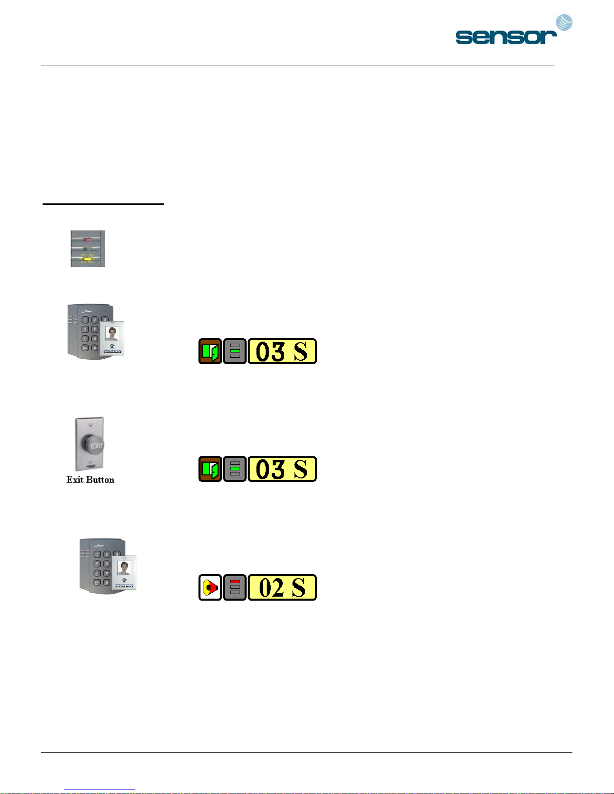
11. OPERATION
11-1. Normal Operation Mode (Safe Mode)
When the Main Unit operates in normal mode, the yellow LED is flashing every
second.
11-2. Open the Door
When a registered Card (or PIN) is read, the Door will open for 3 seconds along
with the"do-mi-sol-do" melody.
Registered Card (or PIN)
11-3. Exit (Open the Door)
To request for exit from the inside, an Exit Button can be used to open the door for
the same duration as in 11-2.
11-4. Action And Alarm Caused by Unregistered Card (or PIN)
When an unregistered Card (or PIN) is read, thus, access is denied and the Alarm
can be activated for 2 seconds along with "sol-do-sol-do" melody.
Unregistered Card (or PIN)
(If you do not want to activate the Alarm in case of unregistered access attempt, then you can change this
setting as shown in section 12.)
13
Page 14
SENSORPROX 100R/PIN120 -
SINGLE DOOR CONTROLLER
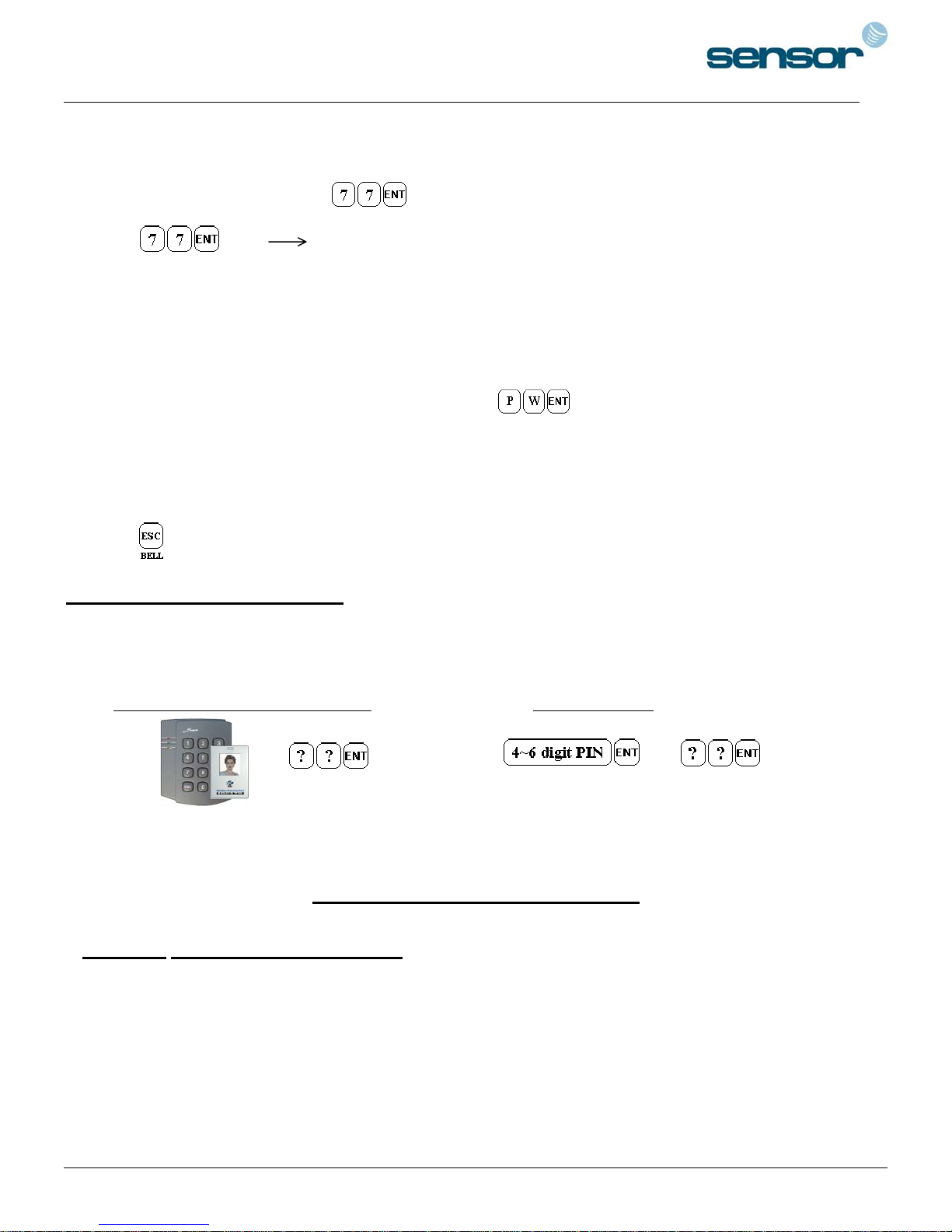
11-5. Secure Mode
The last person to exit can change the operation of the unit from Normal Mode to Secure Mode by
entering the Secure Code of onto the keypad.
Change to Secure Mode.
The Secure Mode will revert back to the normal mode when a registered card (or PIN) is
presented/entered.
11-6. DURESS Alarm
In case of Duress, enter the 2 digit Duress Password and the door will open as usual;
however, the Duress Alarm (TTL Output) will activate an external Auto-Dialer to notify the appropriate
personnel. See section 9.7 and 12.29 for more instructions on this feature.
11-7. Chime Bell Operation
The key can be used to activate an external Chime Bell for 5 seconds, the defaulted value.
12. SETTING CHANGES
Configuration Card/PIN is required to change existing or defaulted setting values or to manage user’s access.
First, present the Configuration Card (or enter the Configuration PIN) and enter the 2-digit command code.
RF Only Mode or RF + PIN Mode PIN Only Mode
+ or +
Configuration Card Command Code Configuration PIN Command Code
Summary Table of Commands
Command Action/Change setting values
11 Add User Access Cards (RF CARD ONLY MODE)
12 Add User Access Cards and PIN (RF CARD + PIN MODE)
13 Add User Access PIN numbers (PIN ONLY MODE)
14 Delete User Access Cards (or PIN)
21 Change Door open time when User Access Card (or PIN) is granted
22 Change Alarm time when User Access Card (or PIN) is denied
23 Change Alarm time when Try-Out error detected
14
Page 15

SENSORPROX 100R/PIN120 -
SINGLE DOOR CONTROLLER
24 Change Alarm time when Door-Contact error detected
25 Change Alarm time when Aux Input #1 detected
26 Change Alarm time when Aux Input #2 detected
27 Change Alarm time when Aux Input #3 detected
28 Change Alarm time when magnet detected
29 Register 2 digits Duress Alarm password
30 Change Alarm time when Duress Alarm detected
31 Test Door open time set by command "21"
32 Test Alarm time set by command "22"
33 Test Alarm time set by command "23"
34 Test Alarm time set by command "24"
35 Test Alarm time set by command "25"
36 Test Alarm time set by command "26"
37 Test Alarm time set by command "27"
39 Change Chime Bell activating time
41 Open door unconditionally
42 Close door unconditionally
43 Enable QUICK ACCESS MODE
44 Disable QUICK ACCESS MODE
51 Disable Melody sound (turning off both the melody & keypress audio feedback)
52 Enable Melody sound
60 Change keypad lock-out time when Try-Out error detected
61 Set Aux Input #1 Detection from ‘L’ to ‘H’
62 Set Aux Input #1 Detection from ‘H’ to ‘L’
63 Set Aux Input #2 Detection from ‘L’ to ‘H’
64 Set Aux Input #2 Detection from ‘H’ to ‘L’
65 Set Aux Input #3 Detection from ‘L’ to ‘H’
66 Set Aux Input #3 Detection from ‘H’ to ‘L’
67 Set Exit Button Input Detection from ‘L’ to ‘H’
68 Set Exit Button Input Detection from ‘H’ to ‘L’
69 Set Door-Contact sensor Input Detection from ‘L’ to ‘H’
70 Set Door-Contact sensor Input Detection from ‘H’ to ‘L’
71 Activate TTL output to ‘H’
72 Activate TTL output to ‘L’
77 Enable Chime Bell Output
78 Disable Chime Bell Output
80 Set delay time to activate SECURE MODE
81 Set Door Open time-out for Door-Contact sensor
82 Set number of times of Try-Out
83 Set input keypress time-out time
15
Page 16
SENSORPROX 100R/PIN120 -
SINGLE DOOR CONTROLLER
84 Set Tamper Alarm output port
88 Enable Tamper Alarm
89 Disable Tamper Alarm
99 Re-Initialize and erase all setup data
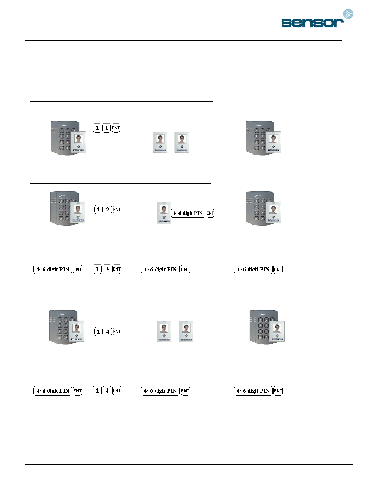
12-11. Add User Access Cards (RF CARD ONLY MODE)
…..
Configuration Card Command Cards to be registered .... Configuration Card
12-12. Add User Access Cards (RF CARD + PIN MODE)
…..
Configuration Card Command Cards to be registered .... Configuration Card
12-13. Add User Access PIN (PIN ONLY MODE)
…..
Configuration PIN Command PINs to be registered .... Configuration PIN
12-14.1. Delete User Access Cards (RF CARD ONLY MODE & RF CARD + PIN MODE)
…..
Configuration Card Command Cards to be deleted .... Configuration Card
12-14.2. Delete User Access PIN (PIN ONLY MODE)
…..
Configuration PIN Command PINs to be deleted .... Configuration PIN
16
Page 17
SENSORPROX 100R/PIN120 -
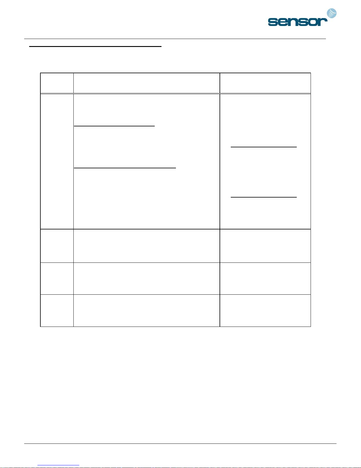
<TABLE 1> SETTINGS FOR COMMAND
SINGLE DOOR CONTROLLER
Symbol Setting Values Examples/Remarks
Output
Mode
(OM)
(You must add value • and •)
Setting value for activating time
• Activate Mode Value
Activate only in Secure Mode : 00
Activate in Safe & Secure Mode : 50
Setting Value for activating Output Port
• Activate Output Port Value
Activate only Door Relay : 01
Activate only Alarm Relay : 02
Activate only TTL Output : 04
Activate Door Relay & TTL : 05
Activate Alarm Relay & TTL : 06
EX1)Activate Door Relay
In Safe & Secure Mode
• Safe & Secure Mode 50
• Door Relay 01
OM = 51
EX2)Activate Alarm Relay
& TTL only in Secure mode
• Secure Mode 00
• Alarm Relay & TTL 06
OM = 06
tt
PW
mm
tt is the activating time value (seconds)
from 01sec. to 99sec.
PW is the 2 digits Password for
Duress Alarm.
is activating time value (minutes)
mm
from 01min. to 99min.
tt value 00sec. means
no operation.
Do not use ‘77’ for PW as it is
used for Secure Mode
value 00min. means
mm
no operation.
17
Page 18
SENSORPROX 100R/PIN120 -
SINGLE DOOR CONTROLLER
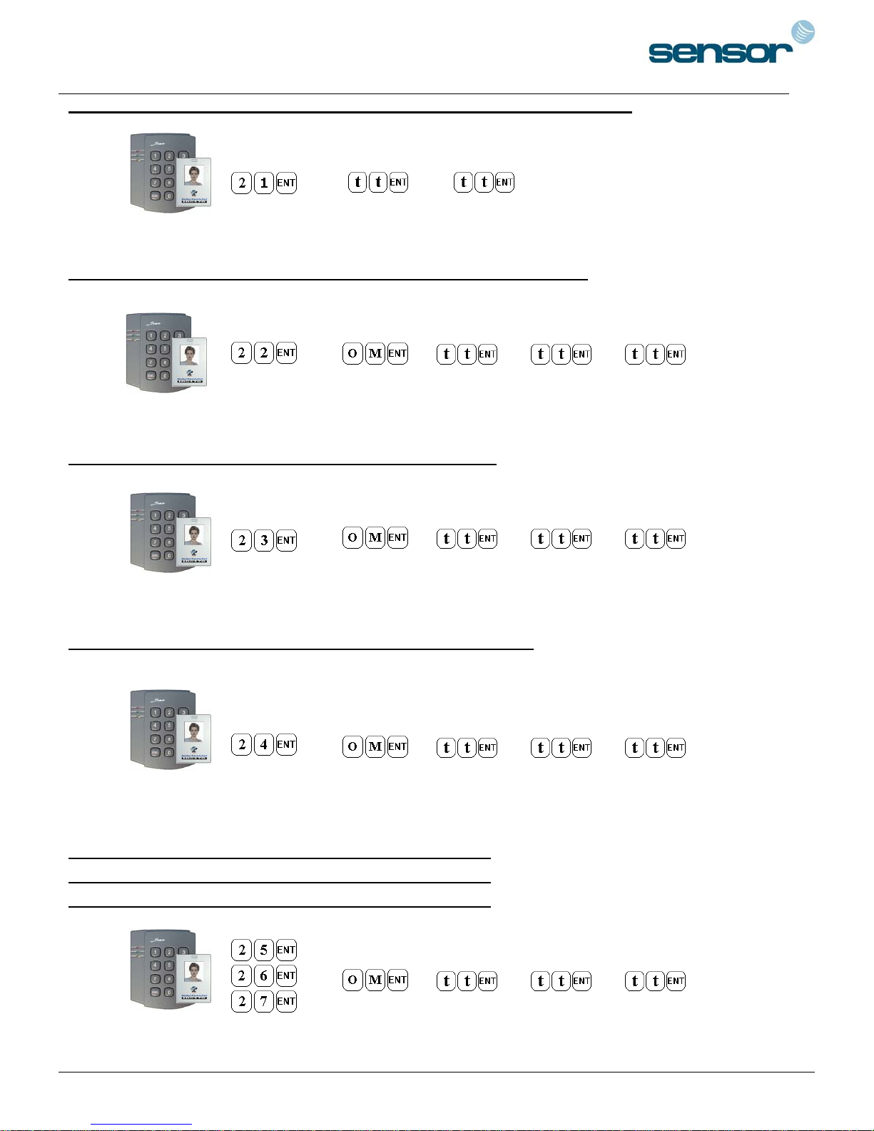
12-21. Change Door Open Time When User Access Card (or PIN) Is Granted
(
=00~99 sec., Defaulted Door Open time = 03 sec.)
tt
Configuration Card Command Door open time TTL time
/Configuration PIN
12-22. Change Alarm Time When User Access Card (or PIN) Is Denied
(Refer to Table 1 for OM, tt=00~99 sec., Defaulted Alarm time = 02 sec.)
Configuration Card Command Output Mode Door time Alarm Time TTL time
/Configuration PIN
12-23. Change Alarm Time When Try-Out Error Detected
(Refer to Table 1 for OM, tt=00~99 sec., Defaulted Alarm time = 10 sec.)
Configuration Card Command Output Mode Door time Alarm Time TTL time
/Configuration PIN
12-24. Change Alarm Time When Door Contact Error Detected
(Refer to Table 1 for OM, tt=00~99 sec.)
Door Open Time-out setting is required for activating, refer to 12.81.
Configuration Card Command Output Mode Door time Alarm Time TTL time
/Configuration PIN
12-25. Change Alarm Time When AUX Input #1 Detected
12-26. Change Alarm Time When AUX Input #2 Detected
12-27. Change Alarm Time When AUX Input #3 Detected
(Refer to Table 1 for OM, tt=00~99 sec.)
Configuration Card Command Output Mode Door time Alarm Time TTL time
/Configuration PIN
18
Page 19
SENSORPROX 100R/PIN120 -
SINGLE DOOR CONTROLLER
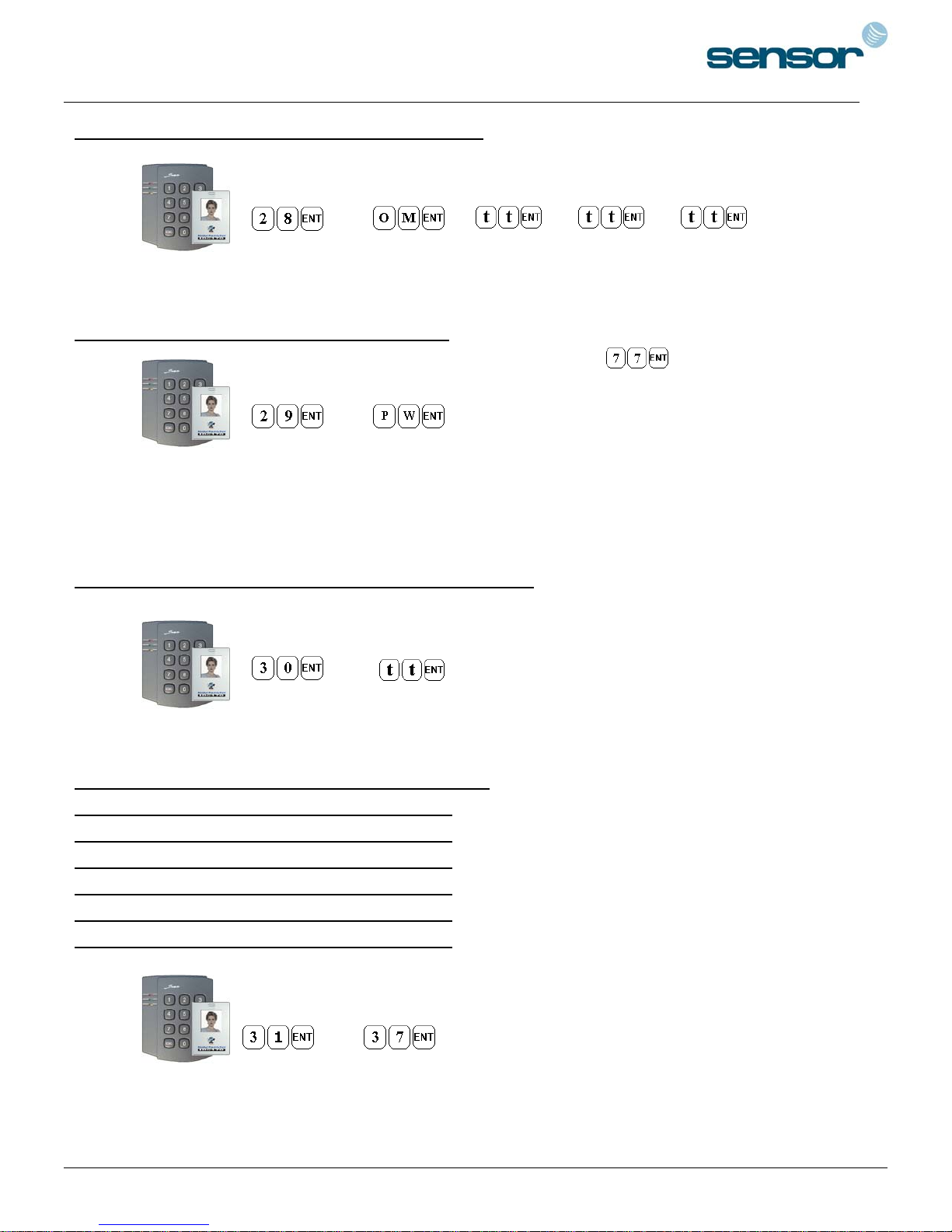
12-28. Change Alarm Time When Magnet Detected
(Refer to Table 1 for OM, tt=00~99 sec.)
Configuration Card Command Output Mode Door time Alarm Time TTL time
/Configuration PIN
12-29. Register 2 Digit Duress Alarm Password
(PW=00~99, Defaulted PW= 00, Do not use )
Configuration Card Command Password
/Configuration PIN
Note: ‘00’ is registered as defaulted Password.
12-30. Change Alarm Time When Duress Alarm Detected
(
=00~99 sec., Defaulted TTL time= 03 sec.)
tt
Configuration Card Command TTL time
/Configuration PIN
12-31. Test Door Open Time Set By Command "21"
12-32. Test Alarm Time Set By Command "22"
12-33. Test Alarm Time Set By Command "23"
12-34. Test Alarm Time Set By Command "24"
12-35. Test Alarm Time Set By Command "25"
12-36. Test Alarm Time Set By Command "26"
12-37. Test Alarm Time Set By Command "27"
Outputs set by command will be tested.
~
Configuration Card Command
/Configuration PIN
19
Page 20
SENSORPROX 100R/PIN120 -
SINGLE DOOR CONTROLLER
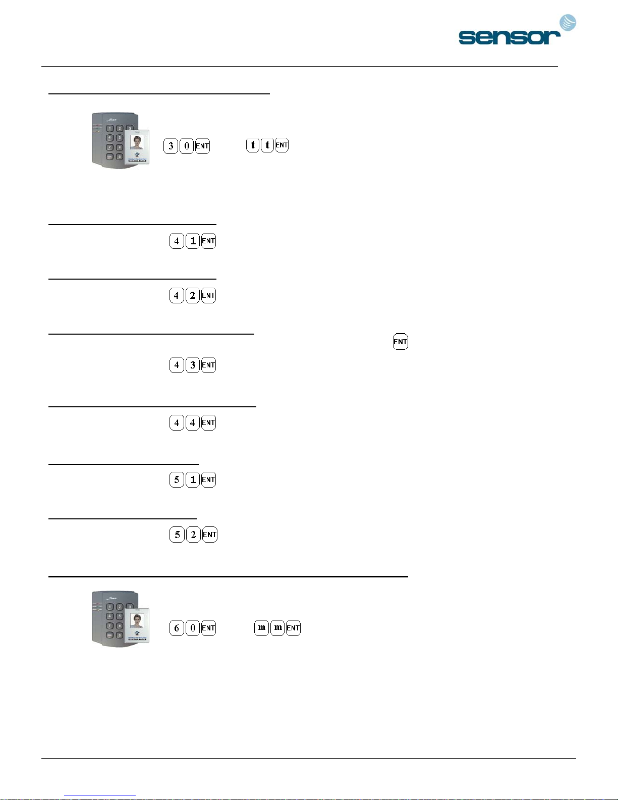
12-39. Change Chime Bell Activating Time
(
=00~99 sec., Defaulted Chime Bell time= 05 sec.)
tt
Configuration Card Command Chime Bell time
/Configuration PIN
12-41. Open Door Unconditional
Configuration Card
/Configuration PIN
12-42. Close Door Unconditional
Configuration Card
/Configuration PIN
12-43. Enable QUICK ACCESS MODE
When QUICK ACCESS MODE is enabled, Door will open simply by press key.
Configuration Card
/Configuration PIN
12-44. Disable QUICK ACCESS MODE
Configuration Card
/Configuration PIN
(Defaulted setting=Disable)
12-51. Disable Melody Sound
Configuration Card
/Configuration PIN
12-52. Enable Melody Sound
Configuration Card
/Configuration PIN
(Defaulted setting=Enable)
12-60. Change Keypad Lock-out Time When Try-Out Error Detected
(
=00~99 min., Defaulted Keypad Lock-out time= 01 min.)
mm
Configuration Card Command Keypad Lock-out time
/Configuration PIN
20
Page 21
SENSORPROX 100R/PIN120 -
SINGLE DOOR CONTROLLER
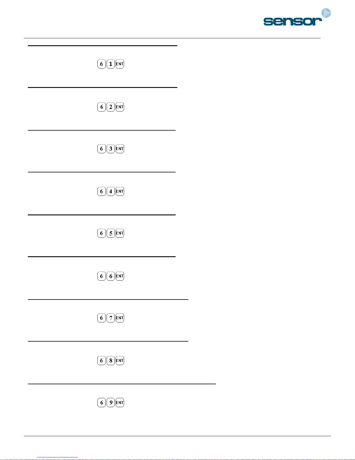
12-61. Set AUX Input #1 Detection from ‘L’ to ‘H’
AUX#1 input is detected on the raising edge of AUX#1 input
Configuration Card
/Configuration PIN
12-62. Set AUX Input #1 Detection from ‘H’ to ‘L’
AUX#1 input is detected on the falling edge of AUX#1 input
Configuration Card
/Configuration PIN
(Defaulted setting)
12-63. Set AUX#2 Input Detection from ‘L’ to ‘H’
AUX#2 input is detected on the raising edge of AUX#2 input
Configuration Card
/Configuration PIN
12-64. Set AUX#2 Input Detection from ‘H’ to ‘L’
AUX#2 input is detected on the falling edge of AUX#2 input (Defaulted setting)
Configuration Card
/Configuration PIN
12-65. Set AUX#3 Input Detection from ‘L’ to ‘H’
AUX#3 input is detected on the raising edge of AUX#3 input
Configuration Card
/Configuration PIN
12-66. Set AUX#3 Input Detection from ‘H’ to ‘L’
AUX#3 input is detected on the falling edge of AUX#3 input (Defaulted setting)
Configuration Card
/Configuration PIN
12-67. Set Exit Button Input Detection from ‘L’ to ‘H’
Exit Button input is detected on the raising edge of Exit Button input
Configuration Card
/Configuration PIN
12-68. Set Exit Button Input Detection from ‘H’ to ‘L’
Exit Button input is detected on the falling edge of Exit Button input (Defaulted setting)
Configuration Card
/Configuration PIN
12-69. Set Door Contact Sensor Input Detection from ‘L’ to ‘H’
Door Contact input is detected on the raising edge of Door Contact input
Configuration Card
/Configuration PIN
21
Page 22
SENSORPROX 100R/PIN120 -
SINGLE DOOR CONTROLLER
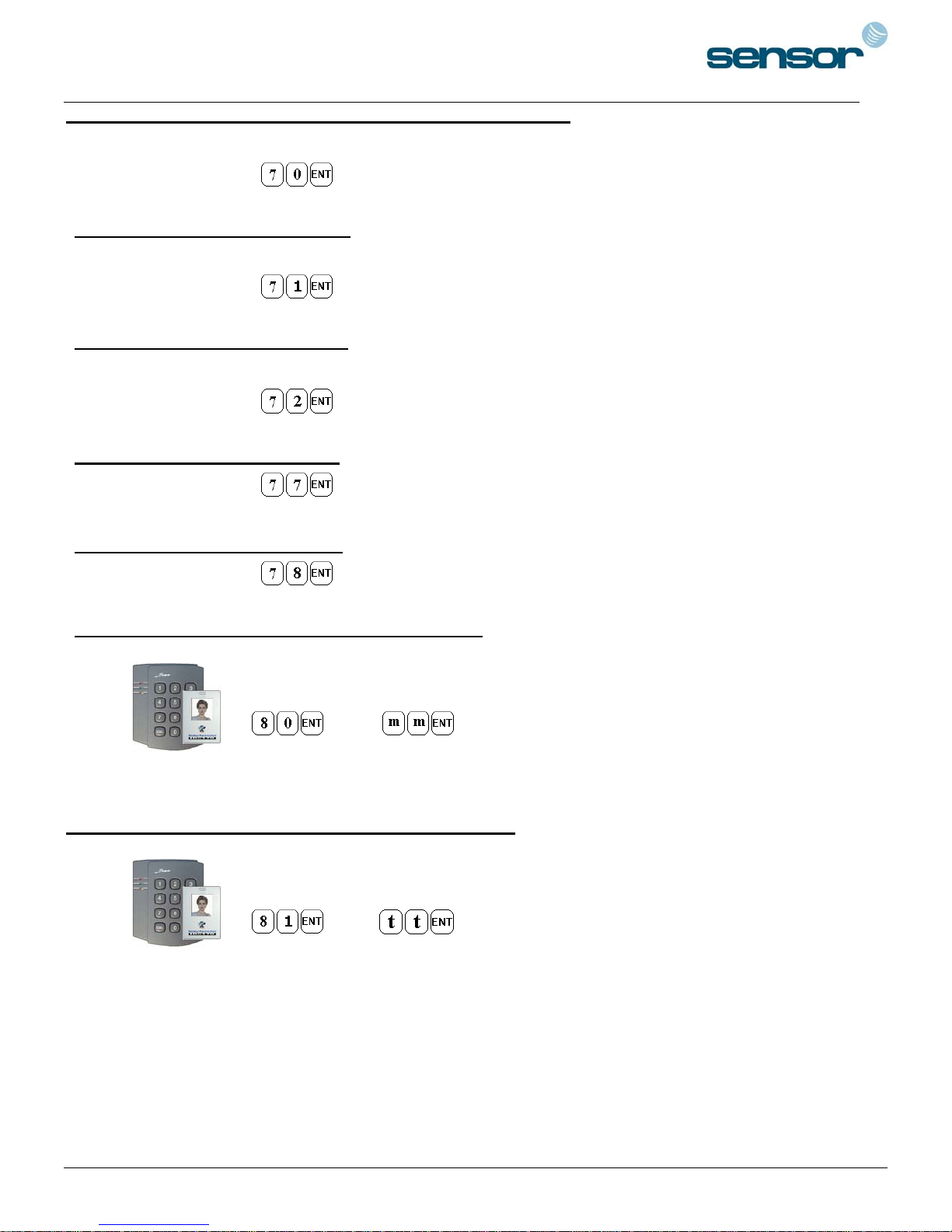
12-70. Set Door Contact Sensor Input Detection from ‘H’ to ‘L’
Door Contact input is detected on the falling edge of Door Contact input
Configuration Card
/Configuration PIN
(Defaulted setting)
12-71. Activate TTL Output to ‘H’
TTL output changes the state from logic '0' to logic '1' when it activates.
Configuration Card
/Configuration PIN
12-72. Activate TTL Output to ‘L’
TTL output changes the state from logic '1' to logic '0' when it activates. (Defaulted setting)
Configuration Card
/Configuration PIN
12-77. Enable Chime Bell Output
Configuration Card
/Configuration PIN
(Defaulted setting=Enable)
12-78. Disable Chime Bell Output
Configuration Card
/Configuration PIN
12-80. Set Delay Time to Activate SECURE MODE
(
=00~99 min., Defaulted Delay time= 00 min.)
mm
Configuration Card Command Delay time
/Configuration PIN]
12-81. Set Door Open Time-out for Door Contact Sensor
(
=00~99 sec., Defaulted value = 00 sec. means no detect Door Contact Sensor, refer
tt
to 12.24 for Alarm time settings)
Configuration Card Command Door Open time-out
/Configuration PIN
22
Page 23
SENSORPROX 100R/PIN120 -
SINGLE DOOR CONTROLLER
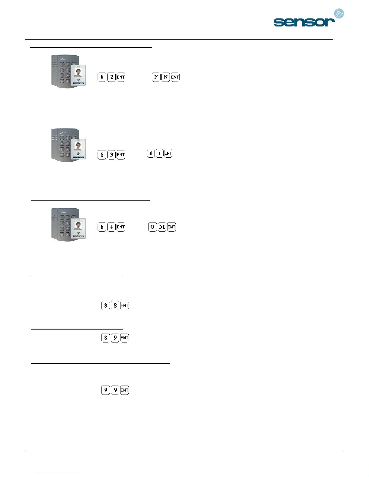
12-82. Set Number of Times of Try-Out
(NN=00~99 times, Defaulted Try-out numbers= 05 times)
Configuration Card Command Try-out numbers
/Configuration PIN
12-83. Set Input Keypress Time-out Time
(
=10~99 sec., Defaulted Keypress time-out= 20 sec.,
tt
Minimum
tt
= 10 sec.)
Configuration Card Command Keypress time-out time
/Configuration PIN
12-84. Set Tamper Alarm Output Port
(Refer to Table 1 for OM, Defaulted Output port= 02 Alarm Relay)
Configuration Card Command Alarm Output Port
/Configuration PIN
12-88. Enable Tamper Alarm
To comply with UL 294, the Standard for Access Control System Units, the Tamper Alarm must
be enabled.
Configuration Card
/Configuration PIN
12-89. Disable Tamper Alarm
Configuration Card
/Configuration PIN
(Defaulted setting)
12-99. Re-Initialize and Erase All Setup Data
Please use this command when you really want to erase all data and start
the unit from the beginning.
Configuration Card
/Configuration PIN
23
Page 24
SENSORPROX 100R/PIN120 -
Additional Function
•
SINGLE DOOR CONTROLLER
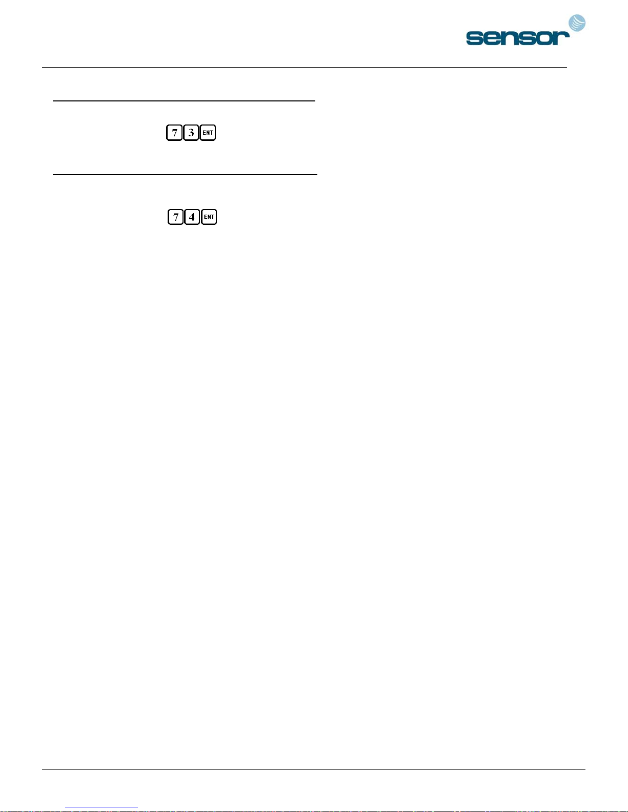
12-73. Enable Keypad Input To Enter ID Number
Keypad input is enabled to enter the ID numbers through keypads.
Configuration Card
/Configuration PIN
12-74. Disable Keypad Input To Enter ID Number
Keypad input is disabled to enter the ID numbers through keypads.
(Defaulted setting)
Configuration Card
/Configuration PIN
24
Page 25

SENSORPROX 100R/PIN120 -
13. FCC REGISTRATION INFORMATION
SINGLE DOOR CONTROLLER
FCC REQUIREMENTS PART 15
Caution: Any changes or modifications in construction of this device which are not expressly approved by the manufacturer for
compliance could void the user's authority to operate the equipment.
NOTE: This device complies with Part 15 of the FCC Rules.
Operation is subject to the following two conditions;
1. This device may not cause harmful interface, and
2. This device must accept any interference received, including interference that may cause undesired operation.
This equipment has been tested and found to comply with the limits for a Class A Digital Device, pursuant to Part 15 of the FCC
Rules. These limits are designed to this equipment generates, uses, and can radiate radio frequency energy and, if not installed and
used in accordance with the instructions, may cause harmful interference to radio communications.
However, there is no guarantee that interference will not occur in a particular installation. If this equipment does cause harmful
interference to radio or television reception, which can be determined by turning the radio or television off and on, the user is
encouraged to try to correct interference by one or more of the following measures.
1. Reorient or relocate the receiving antenna.
2. Increase the separation between the equipment and receiver.
3. Connect the equipment into an outlet on another circuit.
4. Consult the dealer or an experienced radio/TV technician for help.
25
Page 26
SENSORPROX 100R/PIN120 -
15. TEMPLATE
SINGLE DOOR CONTROLLER
26
 Loading...