

Preliminary Information
RF by
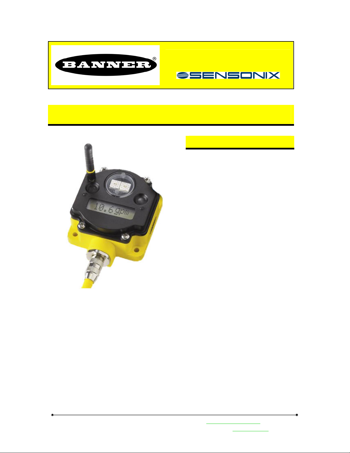
DX80 Gateway Installation & Operation Manual
The gateway and endpoint nodes communicate over multiple wireless channels within the 902-928MHz
ISM Spectrum. Different configurations of internal & external antennas and different RF power options
allow you to customize the wireless range from a few feet to > 10000’. The implementation of FHSS
methodology allows for reliable communications even in harsh industrial environments. The gateway
station and endpoint nodes communicate with acknowledge handshaking to verify reception of data. Error
checking is also performed to validate the data transmission.
The Gateway and Endpoint node communications always collect signal strength information. The
collected data can help gauge the strength and performance of the wireless signals. The received signal
strength can be adjusted by various parameters such as the TX power settings and Receiver Sensitivity
Modes. Hardware configurations can also impact the signal strength, such as internal / external antenna and
antenna placement.
Features
• Operates in 902-928MHz ISM
Spectrum
• FHSS operation
• RF configurations – up to 150 mw
• External antenna connection
• RS232 / RS485
• 2 Analog In (4-20ma)
• 2 Analog Out (4-20ma)
• 2 Digital In
• 2 Digital Out
• 10-30v DC
• LCD, Control buttons, LED
indicators
• Stand alone operation
• DX80 - NEMA 6, IP67 enclosure
Banner Engineering Corp • Minneapolis, MN USA www.bannerengineering.com • Tel: 763.544.3164
Sensonix Incorporated • Plymouth, MN USA
1 of 18 www.sensonix.com • 763.519.7042
Preliminary Information
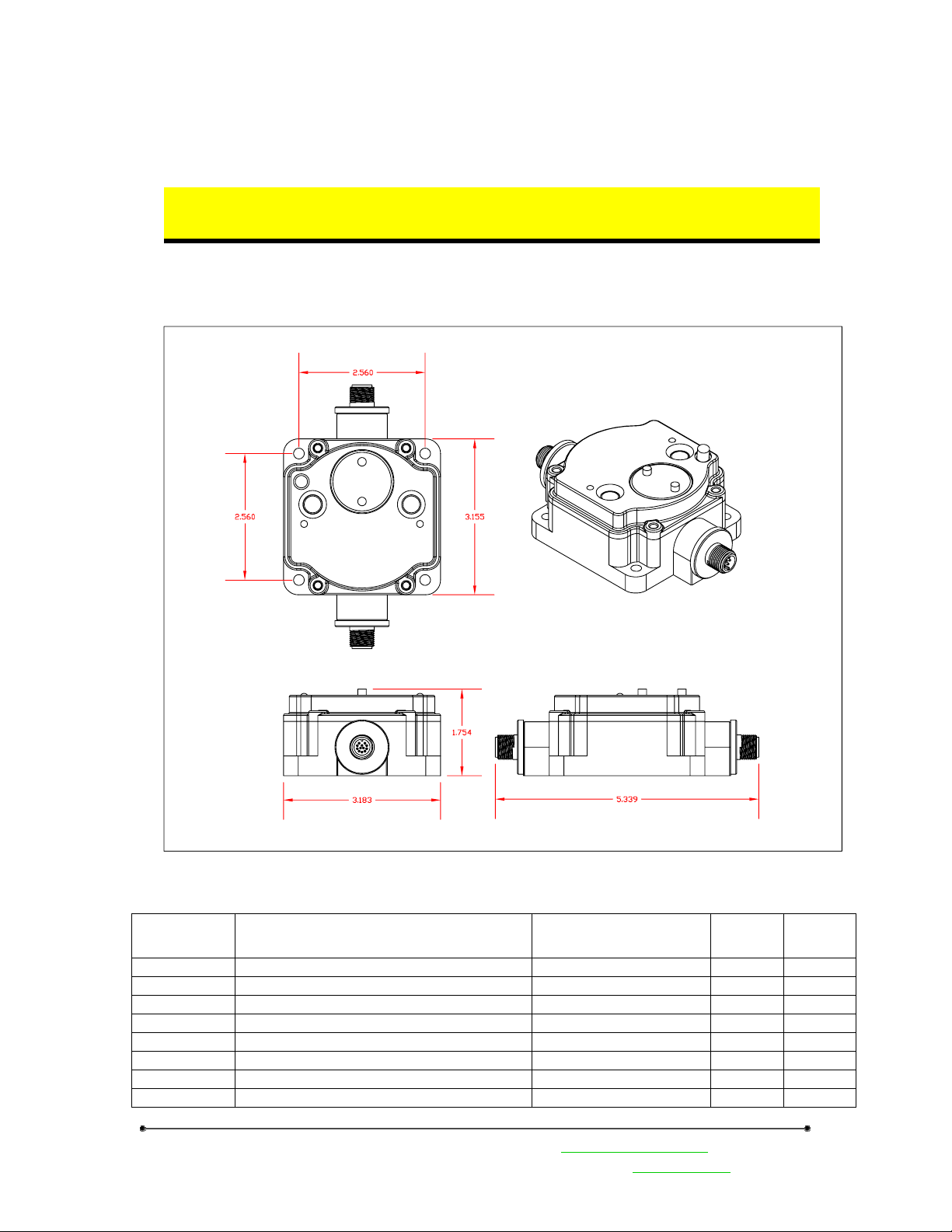
1 Mechanical
Low Profile DX80 enclosure, a two connector model is shown. A DX80 gateway unit
in a single connector model is also available
All DX80 mechanical enclosures
Model # Description Euro Connectors High
Profile
LPGW1 Line Powered Gateway 1 female, 1 male X
LPGW2 Line Powered Gateway 1 male, 8 pin X
LPEN1 Line Powered Endpoint Node 1 female, 1 male X
BPDEN1 Battery Powered Endpoint Node 1 male, 8 pin X
BPMIEN1 Battery Powered Endpoint Node 1 female connector X
BPTMPEN1 Battery, RTD Endpoint Node 2 female connectors X
BPTMPEN2 Battery, Thermocouple Endpoint Node 1 female connector X
BPMG1 Battery, Magnetic Endpoint Node No connectors X
Banner Engineering Corp • Minneapolis, MN USA www.bannerengineering.com • Tel: 763.544.3164
Sensonix Incorporated • Plymouth, MN USA
2 of 18 www.sensonix.com • 763.519.7042
Low
Profile
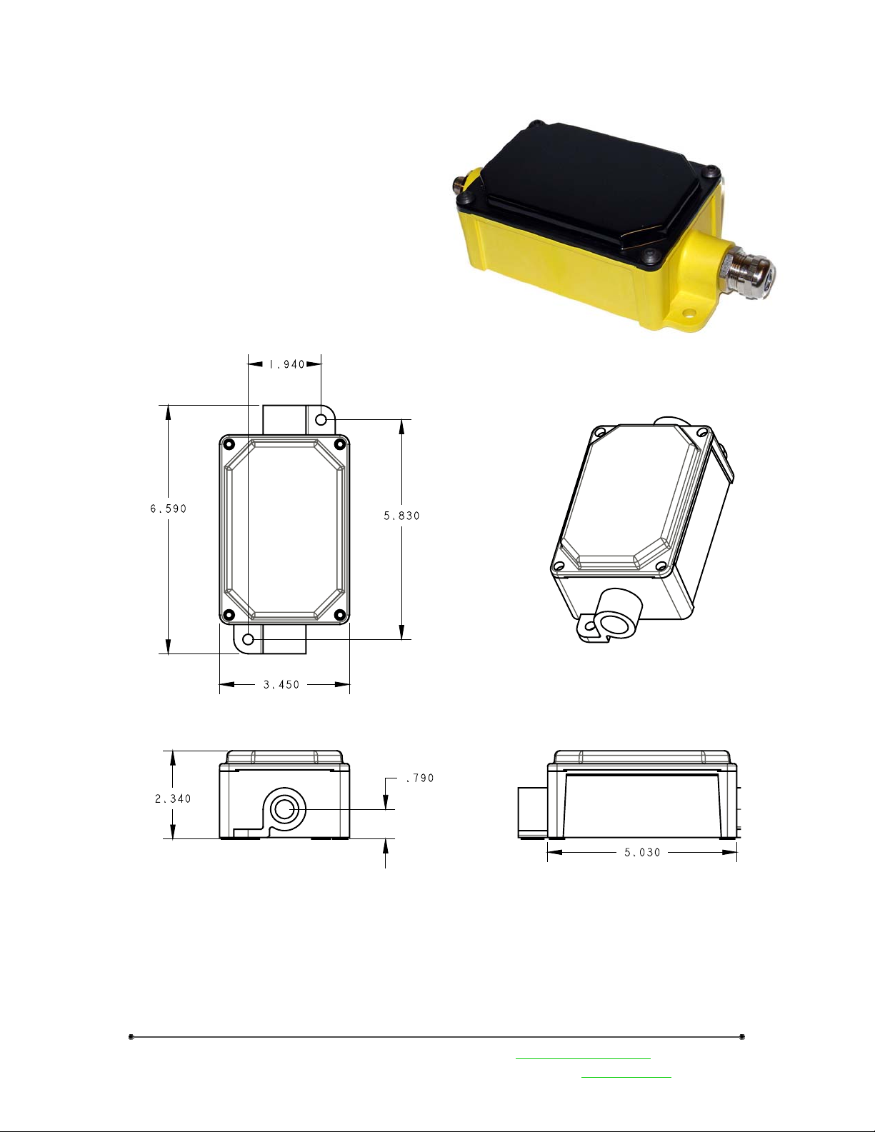
Junction Box
Junction box models – euro connectors, glands,
Euro-style connector or glands?
Mounting holes
Wiring diagram
PC Board with Terminals to identify connection.
Preliminary Information
Banner Engineering Corp • Minneapolis, MN USA www.bannerengineering.com • Tel: 763.544.3164
Sensonix Incorporated • Plymouth, MN USA
3 of 18 www.sensonix.com • 763.519.7042
Preliminary Information
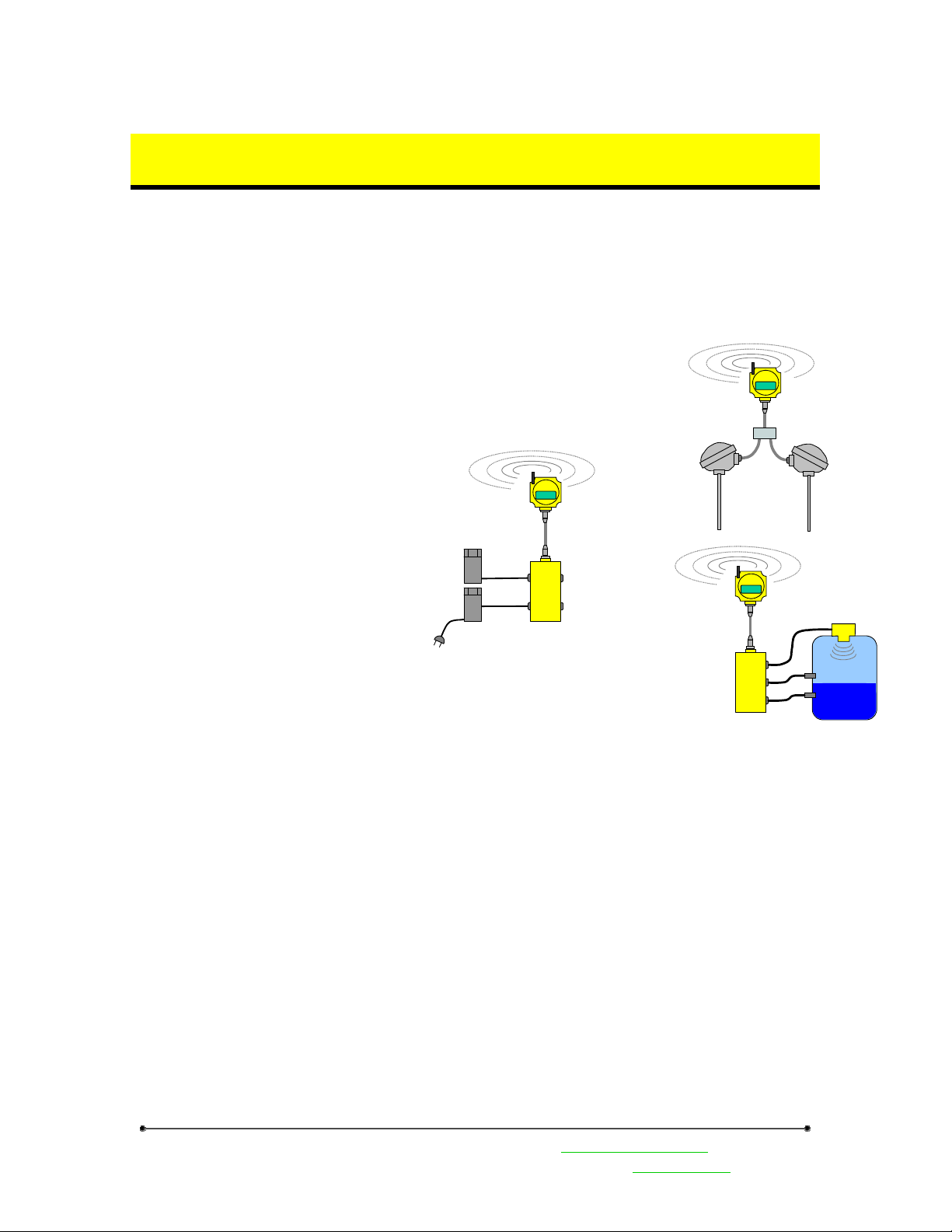
2 Mounting & Electrical Connections
2.1 Placement
A wireless network can be hindered by radio interference as well has obstructions in the path of the
receiver and transmitter. When planning for the best location to install the wireless gateway or endpoint
node, it is best to be able to monitor the signal strength relative to the positions of the devices. A built in
diagnostic called ‘site survey’ continuously monitors signal strength and displays the information on the
gateway front panel LCD. Use this diagnostic tool to confirm signal quality before fixing devices for
permanent installation. (Refer to the
section on Front Panel Operation.)
Avoid placement of the wireless
units in extreme temperatures, high
vibration and high shock areas. The
DX80 is IP67 compliant and designed for
all types of environments but continued
exposure to harsh environments will
shorten the product life.
Although the DX80 devices are
considered maintenance free, try to avoid
installation in an unserviceable location.
Only place the DX80 devices in
ambient operating temperatures of -40°C
to 85°C.
Third
Party
PLC
24Vdc
power
supply
Serial
Interface
123456
Junction
Box
DX80 Line
powered
gateway
2.2 External Antenna
For optimal RF communications the
external antenna should be vertically
mounted. A clear line of sight between
gateway and nodes is ideal.
Only Banner approved external
antenna should be connected to DX80 devices. Unsuitab le antenna may void th e user’s autho rity to op erate
the equipment. The approved antennas are listed in the accessory section.
2
123456
DX80 Battery
powered TC
endpoint node
Thermocouple &
Compensation
Thermistor
1
123456
Junction
Box
Digital sensors
for tank hi/lo
DX80 Battery
powered
endpoint node
QT50
2.3 Mounting hardware requirements
DX80 devices have four #10 screw holes used for mounting the device vertically or horizontally. The
screws should not be tightened more that XX ft/lbs.
Keep in mind sufficient clearances for the external antenna, euro-style connectors and for viewing the
LCD display. The bottom unit dimensions are supplied in the mechanical section of this document.
2.4 Mounting accessories
DIN rail mounting hardware
Antenna mounting hardware, cables
Banner Engineering Corp • Minneapolis, MN USA www.bannerengineering.com • Tel: 763.544.3164
Sensonix Incorporated • Plymouth, MN USA
4 of 18 www.sensonix.com • 763.519.7042
Preliminary Information
2.5 Euro-Style Connectors
The Gateway devices have 8-pin or 12-pin euro-style connectors. The pin numbering and wire color is
identified below. The signal wire to pin number association table identifies all wires for the DX80
Gateway.
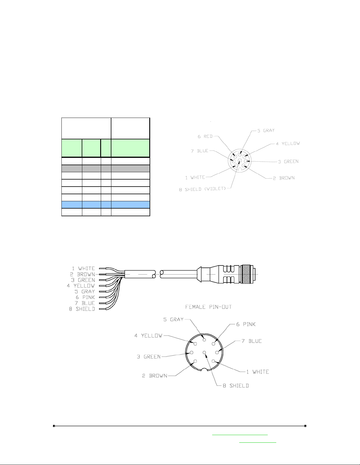
2.5.1 8-pin Euro-Style Wiring (models LPGW2, BPDEN1)
Signal to pin association for 8-pin Euro-Sty l e connectors. DX80 Gateway models
DX80 internal 8-pin Euro Style Connector
(male)
* Looking at the pin end
Euro-Style
Connector
Internal
Wire
Color
White White 1
Brown Brown 2 10-30Vdc
Green Gr een 3 Di gital I nput
Yellow Yellow 4 Courtesy Ground
Gra y Gra y 5 NM OS Ou tp ut
Blue Blue 7 Ground
Vio le t wire 8
Cable
Pin
Wire
Color
Red Pink 6
#
8-Pin Euro-Style Cable
LPGW2 –
Line Powe red
Gate wa y
Euro Q D1 male
Shield
Banner Engineering Corp • Minneapolis, MN USA www.bannerengineering.com • Tel: 763.544.3164
Sensonix Incorporated • Plymouth, MN USA
5 of 18 www.sensonix.com • 763.519.7042

2.5.2 12-pin Euro-Style Wiring
Signal to pin association for 12-pin Euro-Style connectors. DX80 Gateway models
Euro-Sty le Connector
LPGW1 –
Internal
Wire Color
White White 1 -
Bro wn Bro wn 2 10-30Vdc Outpu t 10-30V dc Input
Green Green 3 Analog In1 (4-20mA) RS485 Yellow Yellow 4 Analog Out1 (4-20mA) RS485 +
Grey Grey 5 Analog In2 (4-20mA) RS485 Signal Gnd
White/Red Pink 6 Analog Out2 (4-20mA) -
Blue Blue 7 Ground Ground
Red Red 8 - RS232Tx
Orange Orange 9 Di gital I n1 RS 232R x
White/Bl ack Tan 10 Digital Out1 -
Black Black 11 Di gital I n2 -
Violet Violet 12 Digital Out 2 -
Cable
Wire
Color
Pin # Euro QD1 female Euro QD2 male
Line Powered Gateway
Looking at the connection pin end
Preliminary Information
Banner Engineering Corp • Minneapolis, MN USA www.bannerengineering.com • Tel: 763.544.3164
Sensonix Incorporated • Plymouth, MN USA
6 of 18 www.sensonix.com • 763.519.7042

Preliminary Information
2.6 ModBus Communications, RS232 / 485 (model LPGW1)
The gateway interface is controlled using the Modbus RTU protocol. The gateway device operates as
a Modbus slave device with a programmable slave address in the range of 01-99. The serial interface is set
up with factory default parameters of 19.2k baud, one start bit, two stop bits, no flow control and a slave
address of ‘01’.
The following Modbus function codes are supported. For DX80 configuration commands and DX80
user commands refer to the DX80 Inte rf ace Prot ocol document.
Type
Modbus Cmd 1 0x1 Read Coils, 1 – 2000 contiguous status of coils
Modbus Cmd 2 0x2 Read Discrete Inputs, 1 – 2000 cont i g u ous st at us of discret e inputs
Modbus Cmd 3 0x3 Read Holding Regist ers, 1 – 12 5, cont i g uo u s bl ock of holding regs.
Modbus Cmd 4 0x4 Read Input Registers, 1 – 125, contiguous block of input registers
Modbus Cmd 5 0x5 Write Single Coil
Modbus Cmd 6 0x6 Write Single Register
Modbus Cmd 15 0xF Write Multiple Coils, 1 – 0x7B0 force multiple coils, ON or OFF
Modbus Cmd 16 0x10 Write Multiple Registers, 1 – 0x78, contiguous block of registers
The gateway front panel LED’s are used to display information about the Modbus serial
communications.
LED1
• ‘GREEN’ when power is applied and the gateway is operational.
• ‘RED’ indicates a system error has occurred. Review the LCD display for further
information.
LED2
• ‘YELLOW’ signifies a frame reception or sending.
• ‘RED’ signals an internal Modbus error has occurred.
• Flashing ‘RED’ indicates a communications fault or configuration error.
The RS485 connections are on the 12-pin euro-style male connector QD2 on the gateway. See the Euro
Connector Diagram section in this manual
Function
Code
Description
Banner Engineering Corp • Minneapolis, MN USA www.bannerengineering.com • Tel: 763.544.3164
Sensonix Incorporated • Plymouth, MN USA
7 of 18 www.sensonix.com • 763.519.7042

Preliminary Information
3 Setup & Operation
3.1 DX80 Front Panel
The DX80 front panel picture helps identify
each switch, button and LED. The rotary switches in
the middle of the round window are identified as a
10’s switch (left switch) and a 1’s switch (right
switch). The value for each rotary switch is 0 – 9.
The rotary switches define different parameters
depending upon the current operating state and
whether the device is a gateway or node.
During Run Mode the gateway rotary switches
define the device information to display; the node
switches indicate the node ID number.
During configuration of the Network ID, the
rotary switches indicate the network ID number on
both the gateway and the node.
During configuration of the Modbus slave
number the gateway rotary switches indicate the
Modbus slave number 01-99.
During Site Survey operations the gateway
switches define the node ID number; the node rotary
switches define the node ID number.
The gateway front panel LED’s are used to display information about the Modbus serial
communications
LED1
• ‘GREEN’ when power is applied and the gateway is operational.
• ‘RED’ indicates a system error has occurred. Review the LCD display for further
information.
LED2
• ‘YELLOW’ signifies a frame reception or sending.
• ‘RED’ signals an internal Modbus error has occurred.
• Flashing ‘RED’ indicates a communications fault or configuration error.
The gateway LCD panel will display a variety of information about the gateway and wireless system.
3.2 Power on / Power Off
The gateway and nodes can be powered up or powered down with button 1. When the device is
powered down (sleep mode), depress button 1 for 2-3 seconds, the device will activate. Holding down
button1 for 2-3 seconds when the device is active will cause the device to power off. The wireless devices
are not operational when in Sleep Mode.
Banner Engineering Corp • Minneapolis, MN USA www.bannerengineering.com • Tel: 763.544.3164
Sensonix Incorporated • Plymouth, MN USA
8 of 18 www.sensonix.com • 763.519.7042

Preliminary Information
3.3 Set-up / Configuration
The gateway and nodes must be configured to create a communications link. A properly running
wireless network will be indicated on each endpoint node by LED1 flashing green every second. (The
gateway LED’s monitor the Modbus host link)
Complete the following configuration steps to set up the wireless link.
DC power or Battery power applied to all devices and powered up. (out of sleep mode) (See 4.2 Power
on / Power off)
Gateway Set-up –
• Rotary switches = ‘00’
• Network ID set to a common value for the entire wireless network. The factory default is ‘01’
and will work for most single network installations. (See Setting the Network ID to change
the network ID)
• The Modbus slave number must be set to a unique number compared to other slaves on the
serial host bus. This is only required if using a host interface with the gateway.
Node / Endpoint Set-up –
• Rotary switches = unique number for each node in the wireless network. 01-99, 00 is not valid
• LED1 will blink GREEN every second when a RF communications link is established.
• LED1 will blink RED every 3 seconds when a node is not communicating with the gateway.
*Some endpoint nodes may require up to 20 seconds after power-on to synchronize with the gateway.
3.4 LabView Configuration
Node configuration, Sensor configuration,
System Parameters – dynamic TDMA
Banner Engineering Corp • Minneapolis, MN USA www.bannerengineering.com • Tel: 763.544.3164
Sensonix Incorporated • Plymouth, MN USA
9 of 18 www.sensonix.com • 763.519.7042

Preliminary Information
3.5 Front Panel Operation
The front panel rotary switches and push button switches control the display information and
configuration of the DX80 devices. The flow diagram below shows the button sequences and operational
flow for what is possible with the DX80 Gateway.
Sleep
Mode
hold.1
ModBus Slave ID
hold.1
ModBus Baud
Network ID
RF Baud
sc1
RUN
Run Mode
Rotary switches
define device
Sys Warn / Err
Dev Warn / Err
Point 0 status
Point 1 status
Point N status
sc.1
DEVINF
Device Info
sc.2
Rotary switches
define device
Name A
Name B
Name C
RF Msg
Dev Warn / Err
dc.2
sc.1
S/W Cm rev high
FACTRY
Factory
sc.2
Rotary switches
define device
S/N high
S/N low
Mod high
Mod low
S/W RF rev high
S/W RF rev low
S/W Cm rev low
Production high
Production low
dc.2
sc.1
Site Survey Start
DIAG
Diagnostics
sc.2
Password
protect,
Rotary Sw
sc.1
dc.2
CONFIG
Config
sc.2
Password
protect,
Rotary Sw
Config Start
dc.2
hold.1 = press and hold button 1 for 2-3 seconds
sc.1 = single click button 1
sc.2 = single click button 2
dc.2 = double click button 2
From a powered-off state, press and hold button 1 for 2-3 seconds will turn on the Gateway or Node.
From any state, press and hold button 1 for 2-3 seconds will turn off the Gateway or Node. Configuration
steps not fully completed before going into sleep mode will be lost.
3.5.1 Operating States
Sleep Mode – This is the off state for all devices. Sleep mode can be entered or exited by holding
button 1 for 2-3 seconds regardless of the current state. All LED’s will be turned off in this state. (The LCD
display will be turned off for DX80 devices with an LCD display)
Run Mode – (LCD display = ‘RUN’) This is the default operating state for normal operation. Out of
sleep mode the device will transition into run mode. If no buttons changes are detected the gateway will
display device information. The rotary switches on th e gateway will define which device information to
Banner Engineering Corp • Minneapolis, MN USA www.bannerengineering.com • Tel: 763.544.3164
Sensonix Incorporated • Plymouth, MN USA
10 of 18 www.sensonix.com • 763.519.7042

Preliminary Information
display on the LCD. If the rotary switches are set to ‘04’ the information for endpoint node ’04 will be
displayed. The gateway can only display device information if they are defined with Modbus registers.
The LCD will display any system warnings or errors, any device warnings or errors and the state of
each I/O point defined for that device. The LCD display will continuously cycle through this information
until the rotary switches change or a button change is detected.
Device Information (LCD display = ‘DEVINF’) From the Run mode state, single click button 1 to get
to the Device Information selection. Single click button 2 will begin displaying the information for the
device defined by the rotary switches. The LCD will display ‘NAME A’, ‘NAME B’, ‘NAME C’, RF
Message and Device warnings / errors.
The NAME A, B and C fields are a user defined name that can be associated with each device. A total
of 18 characters can be used. The name fields can be defined under the CONFIG menu.
The RF message can be one of several informational messages about the RF link between the gateway
and node. ‘NO RF’, ‘RF OFF’, ‘RF SYNC’ and ‘RF OK’ are the RF messages. ‘NO RF’ indicates there is
no communication link between the device defined by the rotary switches and the gateway. ‘RF OFF’
indicates the device has been disabled. ‘RF SYNC’ indicates that the node and the gateway are in the
process of trying to synchronize communications. All devices should synchronize within 20 seconds of
being enabled. ‘RF OK’ indicates the wireless communications between the gateway and node are
operating normally.
The device warnings and error messages displayed will be for the device defined by the rotary
switches. See the ‘Warnings & Error Messages’ section for full explanations of each message.
To exit the device information state, double click button 2
Factory Settings (LCD display = ‘FACTRY’) From the run mode state, single click button 1 and then
single click button 1 again to arrive at the factory settings display. To begin the cycle through the factory
information display single click button 2. The display information will include: serial number, model
number, software version for the RF processor, software version for the communications processor and the
production date.
To exit the factory settings state, double click button 2.
Banner Engineering Corp • Minneapolis, MN USA www.bannerengineering.com • Tel: 763.544.3164
Sensonix Incorporated • Plymouth, MN USA
11 of 18 www.sensonix.com • 763.519.7042

Preliminary Information
Diagnostics (LCD display = ‘DIAG’) The diagnostic menu is a password protected area. A 4-digit
password must be entered before the system will enter into the diagnostics menus. The default password is
‘0000’. The password is entered starting at the right most character; use the right rotary switch to enter the
proper digit, then single click button 2 to move to the next digit. When all four digits have been properly
entered, double click button 2 to enter the site survey diagnostic.
The Site Survey mode can be used to judge the quality of the RF communications link between the
gateway and any node. Site Survey mode can only be activated from the gateway menu.
The gateway LED1 and LED2 will alternately blink RED to indicate you are now in Site Survey Start.
Now set the rotary switches to a node number to perform the Site Survey testing. Then single click button 1
to activate the node defined by the rotary switches.
dc.1
Deactivate
Device & Reset
Totals
Excellent Reception Total
Site Survey Start
Rotary switches
define device
Good Reception Total
Poor Reception Total
Missed Packet Total
dc.2
sc.1
Activate Device &
Reset Totals
This will cause the LCD on the front panel of both devices (gateway and node) to display the signal
strength for the wireless RF link. A group of 100 data packets are sent at different frequencies between the
gateway and the node. The LCD display will show the breakdown of total missed packets, total poor
reception packets, total good reception packets and the total number of excellent reception packets.
After 100 data packets the whole process is repeated. The LCD display is continually updated with the
running totals for each category.
When testing the communication signal link using site survey, make sure to ke ep all wireless units
separated by at least 3 feet.
Banner Engineering Corp • Minneapolis, MN USA www.bannerengineering.com • Tel: 763.544.3164
Sensonix Incorporated • Plymouth, MN USA
12 of 18 www.sensonix.com • 763.519.7042

Preliminary Information
Configuration (LCD display = ‘CONFIG’) To set the network ID or Modbus Slave nu mber, from
Run Mode single click button 1 until the LCD display reads ‘CONFIG’, now single clock button 2. The
configuration menus are a password protected area. A 4-digit password must be entered before the system
will enter into the configuration menus. The default password is ‘0000’. The password is entered starting at
the right most character; use the right rotary switch to enter the proper digit, then single click button 2 t o
move to the next digit.. Double click button 2 when all four digits have been entered. This will allow access
into the configuration menus.
dc.2
Config Start
sc.1
switches define
Network ID
LCD Display
Current value, Switch value
Enter new value
LCD Display
Current value, Switch value
NET ID
Config
sc.2
Rotary
sc.2
sc.1
sc.1
MODSLV
Config
sc.2
Rotary switches
define Modbus
Slave #
LCD Display
Current value, Switch value
sc.2
Enter new value
LCD Display
Current value, Switch value
sc.1
sc.1
Current value, Switch value
Current value, Switch value
SETPWD
Config
sc.2
Use Rotary
Switches to
Set PW
LCD Display
sc.2
Enter new value
LCD Display
sc.1
sc.1
dc.2
Current value, Switch value
SETNAM
Config
sc.2
Use Button 1
to Set
NAME3,2,1
LCD Display
Display Name3,2,1
sc.2
Enter new value
LCD Display
sc.1
GATWAY
Config
sc.1
NODE
Config
The configuration menu is made up of 4 sub menus: Network ID, Modbus Slave number, Gateway and
Node. Select the appropriate sub menu by single clicking button 2.
Configuration: Network ID. The network ID is a parameter used to define the sequence of RF
channel hops and used to create a unique network ID that will allow devices to communicate with each
other as a wireless network. A wireless network comprised of a gateway and nodes need to be programmed
using the same network ID. For co-locating multiple wireless networks within range of each other, choose
unique network IDs for each wireless network group. The default Network ID setting from the factory is
‘01’.
The network ID is set with the rotary switches. The rotary switches are defined as a 10’s switch and a
1’s switch. For example, if the 10’s switch is set to ‘6’ and the 1’s switch is set to ‘2’ the resulting value is
read as ‘62’.
From within the configuration menu, single click button 1 until the LCD display reads ‘NETID’ and
then single click button 2. The LCD will display the current value of the Network ID and the rotary switch
values. When the rotary switches are set correctly for the new Network ID, enter the new value by a single
click of button 2. The LCD will briefly display the new Network ID before exiting back to the Netwo rk ID
top menu.
If you change the network ID on one device, gateway or node, all devices intended for that
wireless network need to be changed to the same network ID.
Double click button 2 to put the device back into Run Mode.
Banner Engineering Corp • Minneapolis, MN USA www.bannerengineering.com • Tel: 763.544.3164
Sensonix Incorporated • Plymouth, MN USA
13 of 18 www.sensonix.com • 763.519.7042

Preliminary Information
Configuration: Modbus Slave Number. The DX80 gateway can have a Modbus slave address from 1
to 99. Each member of a Modbus RTU serial network must have a unique slave number.
From within the configuration menu, single click button 1 until the LCD display reads ‘MODSLV’ and
then single click button 2. The LCD will display the current value of the Modbus Slave number and the
rotary switch values. When the rotary switches are set correctly for the new Modbus Slave number, enter
the new value by a single click of button 2. The LCD will briefly display the new Modbus Slave number
before exiting back to the Modbus Slave top menu.
Double click button 2 to put the device back into Run Mode.
Set Password: The password is defined as a 4-digit number used to protect the configuration and
diagnostic areas of the menu system.
Set Name: A user name can be applied to each device. Up to 16 alphanumeric characters can be
stored.
Banner Engineering Corp • Minneapolis, MN USA www.bannerengineering.com • Tel: 763.544.3164
Sensonix Incorporated • Plymouth, MN USA
14 of 18 www.sensonix.com • 763.519.7042

Preliminary Information
4 Maintenance
The DX80 family of products is designed to be IP67 compliant and maintenance free. Annual cleaning
and inspection is always recommended. When inspecting the equipment watch for housing cracks, residue
build-up or corrosion on connectors. It is also a good idea to verify the mechanical connections are tight
and still in good condition.
5 Trouble shooting
Network setup
A table of all LCD messages
Banner Engineering Corp • Minneapolis, MN USA www.bannerengineering.com • Tel: 763.544.3164
Sensonix Incorporated • Plymouth, MN USA
15 of 18 www.sensonix.com • 763.519.7042

6 Specifications
RS232 / 485 Serial Interface
Interface RS-232 / RS-485
Baud Rates 19.2k
Data Format 8 data, no parity, 2 stop bit
Protocol ModBus RTU
Radio Specifications
Range
Frequency 902 – 928 MHZ ISM band
Transmit Power Variable
Channel Hopping
Rx Sensitivity To -110 dBm
Antenna Connector
Operating Temperature Range
Electronics
LCD -30C to +70C
LCD reduced visibility
Configurable – few feet to >
10000’
FHSS – configurable # of
channels
External Reverse Polarity
SMA – 50 ohms
-40C to +85C
-40C to +85C
Preliminary Information
Ethernet Interface
Interface Ethernet 10/100
Connection RJ-45 / Hardwired
General
Power 10-30V DC
Power Consumption XX mW
Wiring Connections Two 12-pin Euro-Style Connectors
Mounting
Dimensions 3.15” x 3.15”
Case Material ABS, polycarbonate
Weight
Temperature Ratings -40 to +85ºC
Approvals
Environmental Ratings NEMA 6, IP67
LED Indicators (2) LED
Switches (2) Push Button Switches
LCD 6 Character LCD
DX80 enclosure – horizontal or
vertical mount.
Banner Engineering Corp • Minneapolis, MN USA www.bannerengineering.com • Tel: 763.544.3164
Sensonix Incorporated • Plymouth, MN USA
16 of 18 www.sensonix.com • 763.519.7042

Preliminary Information
Care should be taken to maintain the minimum separation distances specified between the antenna and
nearby persons.
7 Agency Certifications
7.1 FCC
This device compiles with part 15 of the FCC rules. Operation is subject to the following two
conditions: (1) This device may not cause harmful interference, and (2) this device must accept any
interference received, including interference that may cause undesired operation.
This equipment compiles with part 15 of the FCC rules. Any changes or modifications not expressly
approved by the manufacturer could void the user’s authority to operate the equipment.
Antenna usage: This device should be used with the antennas listed on page 17 of this manual.
7.2 UL
913
Intrinsically Safe –
7.3 Environmental Rating
NEMA 6
IP67
8 Accessories
Qualified Antennas
Part
Manufacturer
Nearson S321AH-915 ¼ wave, 3” antenna 0.0 dBi Fixed / Mobile 20 cm
Nearson S463AH-915
Nearson S467AH-915S
Number
Type Gain Application
1/2 wave fixed
antenna
1/2 wave Swivel
antenna
2.0 dBi Fixed / Mobile 20 cm
2.0 dBi Fixed / Mobile 20 cm
Cables
Mounting Brackets
Min. Separation
Distance
Banner Engineering Corp • Minneapolis, MN USA www.bannerengineering.com • Tel: 763.544.3164
Sensonix Incorporated • Plymouth, MN USA
17 of 18 www.sensonix.com • 763.519.7042

Preliminary Information
9 Messages
Endpoint Node
RF link status messages
• RF OK –
• RF Sync –
• RF OFF –
• NO RF –
Warning / Error Messages
LOWBAT – Low battery condition, replace battery.
S FLT – Sensor response is outside of normal operating parameters.
P FLT – Parameter error in processing sensor status.
Gateway
ModBus errors
Banner Engineering Corp • Minneapolis, MN USA www.bannerengineering.com • Tel: 763.544.3164
Sensonix Incorporated • Plymouth, MN USA
18 of 18 www.sensonix.com • 763.519.7042
 Loading...