

Page 1

PROPRIETARY
PAGE 1 OF 5
Reference Guide – NetSense Platform Network Module
Overview
The Sensity Systems NetSense platform introduces an open architecture-based Light Sensory Network
that can be deployed at the same time as Sensity LED retrofits and new LED luminaires.
The NetSense platform leverages standards-based IPv4/6 (Internet Protocol version 4 or 6) data
transports that support a variety of application-specific sensors and software analytics to deliver multiservice capabilities at each LED retrofit/new luminaire.
Savings derived from converting to LED lighting help fund the deployment of this sophisticated platform,
which enables light owners to leverage their investment in LEDs by running a variety of software
applications, spanning both lighting-specific and non-lighting-related services.
Electrical Specifications
AC Input: 100-277 VAC, Max current up to 10A
Environmental Specification
Operating Temperature: -20C to 65C
Storage Temperature: -20C to 85C
Enclosure Suitable for Damp Locations, not directly exposed to outdoor elements
Antenna Specification
External antenna installation is constrained to any Omni-directional antenna rated ≤ 6dbi and
supporting 2.4/ 5GHz frequencies. Antenna specification is provided only by Sensity engineering
and has been validated to meet the requirements imposed by FCC through testing.
Installation Guidelines
NetSense Platform Network Module (LSNM-0001-A) must only be installed into outdoor, non-
residential locations.
Installation is only allowed into approved Sensity Systems luminaires
Module must be installed into a downward facing position relative to ground
Only professional installation is allowed through Sensity authorized factories
Serviceability
There are no serviceable items within the module. Per FCC requirements, the unit cannot be
serviced by any end user; regardless if in-warranty or out of warranty.
If the unit is malfunctioning or causing interference with existing radio devices;
o Determine cause of interference and remove suspect device from service
o Contact Sensity Systems Customer Service at 1-855-500-SENS (7367)
Page 2
PROPRIETARY
PAGE 2 OF 5
Reference Guide – NetSense Platform Network Module
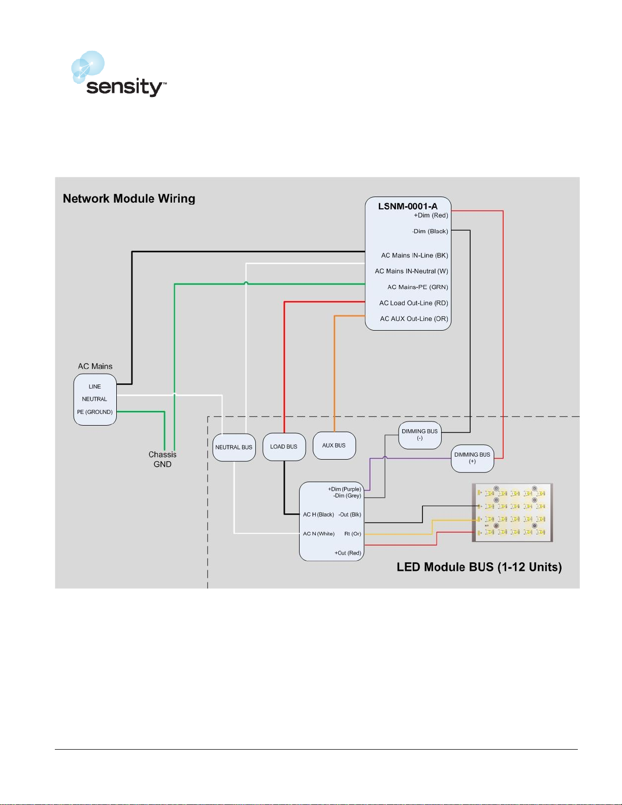
Wiring Installation Guide
Page 3
PROPRIETARY
PAGE 3 OF 5
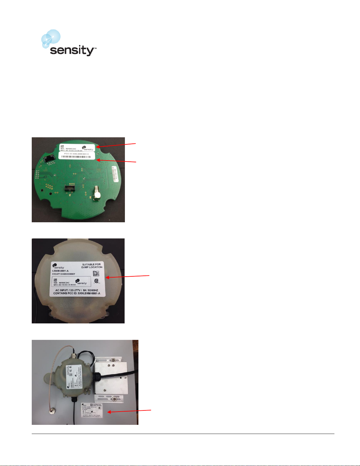
Network Identifier
FCC Identifier
Enclosure Product Identifier
Product Label
Reference Guide – NetSense Platform Network Module
Product Labeling Guidelines
Product is to be labeled in accordance to Sensity Systems LSNM_MarkingRequirements document;
no other changes or revisions to placement, script, font or size is allowed.
Refer to below for brief detail of label placement
Micronode (uNode) Label
Micronode Enclosure Label
Installation Example Label/ Placement
Page 4
PROPRIETARY
PAGE 4 OF 5
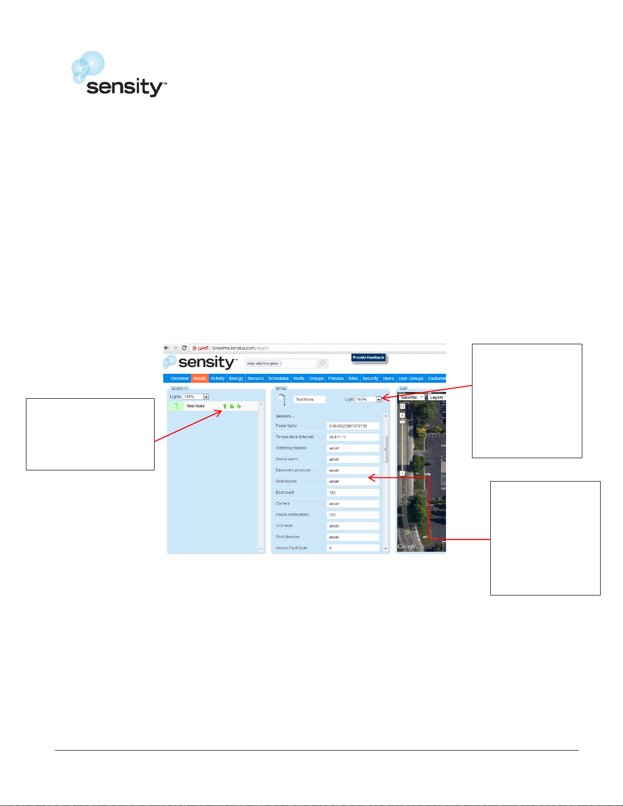
Provides status of
light, WIFI (network
connectivity) and
sensor alarms.
Provides status of
boot counts and
power meter
related values
(current, voltage,
power etc)
Use the menu to
control light and
dimming levels.
Reference Guide – NetSense Platform Network Module
Luminaire Installation and Verification Procedure
Power up luminaire containing netsense networking element using rated voltage. Network Node
should connect to wireless gateway/repeater automatically once power is applied
Connect to customer server to control and collect data from a luminaire containing network node.
Note: Please contact your sales representative if web address, userid and password is not provided.
Verify following items from the server website:
o Network node appears on the server. (If network node do not appear on the server, there please
verify that gateway/repeaters are powered up.)
o The WIFI status shows network connection.
Verify that dimming functionality controlled by network node and LED driver work as expected (dim
from 100 to 50% and turn on/off light).
Verify that temperature (external) measured by sensor is within reasonable values.
Move luminaire from original location to correct location by changing latitude/longitude or dragging
the symbol.
Picture showing key identifier on LSN server website
Page 5

PROPRIETARY
PAGE 5 OF 5
Reference Guide – NetSense Platform Network Module
FCC Statement:
This device complies with part 15 of the FCC Rules. Operation is subject to the following two conditions:
(1) This device may not cause harmful interference, and
(2) This device must accept any interference received, including interference that may cause
undesired operation.
This equipment has been tested and found to comply with the limits for a Class A digital device, pursuant
to part 15 of the FCC rules. These limits are designed to provide reasonable protection against harmful
interference in a commercial installation. This equipment generates, uses and can radiate radio
frequency energy and, if not installed and used in accordance with the instructions, may cause harmful
interference to radio communications. However, there is no guarantee that interference will not occur in
a particular installation. If this equipment does cause harmful interference to radio or other
communication devices, which can be determined by turning the equipment on and off, the user is
encouraged to try and correct the interference by one or more of the following measures:
Reorient or relocate the receiving antenna
Increase the separation between the equipment and the receiver
Contact the manufacturer for additional support.
The FCC requires the user to be notified that any changes to modifications made to this device that are not
expressly approved by Sensity Systems, will void the user’s authority to operate the equipment.
 Loading...