

Page 1
INSTRUCTION MANUAL
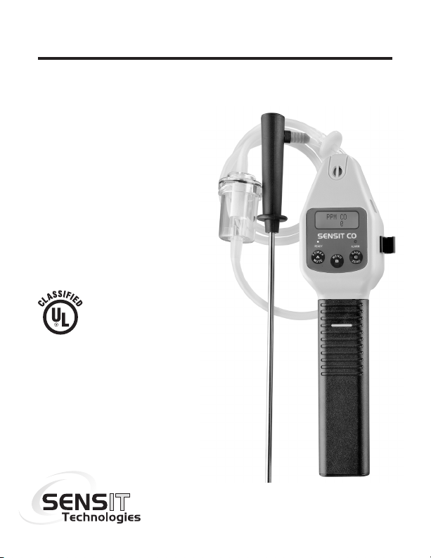
SENSIT® CO
Carbon Monoxide Analyzer
Read and understand
instructions before use.
7WA6
Approved UL913, For Class 1,
Division 1, Groups C & D
hazardous locations when used
with alkaline or NiMH batteries.
Warning: To prevent ignition of ammable
or combustible atmospheres, disconnect
power before servicing.
Find Q uality Pro ducts Onli ne at: sales@ GlobalTestSupp ly.com
www.GlobalTestSupply.com
Page 2

FOR YOUR SAFETY
NOTICE: ⚠ CAUTION: This safety symbol is used to
indicate a potentially hazardous situation which, if not
avoided, may result in minor or moderate injury.
⚠ Warning: To prevent the risk of ignition of ammable
atmospheres, batteries must only be changed in an area known
to be non-hazardous.
⚠ Warning: To prevent ignition of ammable or combustible
atmospheres, disconnect power before servicing.
Do not mix batteries of different age or type.
CARBON MONOXIDE EXPOSURE
STANDARDS AND HEALTH EFFECT CHART
LEVEL EFFECT
0 ppm Desired level - No Effect
9 ppm Acceptable level in a living space*
50 ppm Maximum level for continuous exposure in any 8 hour period
400 ppm Frontal headaches in 1 to 2 hours, life threatening after 3 hours
800 ppm Nausea and convulsions, death within 2 hr.
1,600 ppm Nausea within 20 min., death within 1 hr. **
12,800 ppm Death within 1-3 minutes**
* Always consider outdoor ambient conditions
** Health effects can vary signicantly based on age, sex, weight and overall health.
ii
Find Q uality Pro ducts Onli ne at: sales@ GlobalTestSupp ly.com
www.GlobalTestSupply.com
Page 3

TABLE OF CONTENTS
Preparation
For Your Safety .............................................................. ii
Table of Contents....................................................... 3-4
Parts and Accessories ...................................................5
General Description .......................................................6
Product Specications ...................................................7
Product Features ..................................................... 8-10
Basic Operation
Battery Installation/Replacement .................................11
Operation and Use ................................................ 12-14
Calibration Check ........................................................15
User Menu
User Menu / Function Descriptions .............................16
User Menu Operation
Printing to Optional IR Printer ......................................17
Power Off - Automatic Shut-Off ...................................18
3
Find Q uality Pro ducts Onli ne at: sales@ GlobalTestSupp ly.com
www.GlobalTestSupply.com
Page 4

TABLE OF CONTENTS
User Menu Operation
Set Clock .....................................................................19
Calibration Log: Show and Print Calibration Log .........20
Session Log: Show and Print Session Log............ 21-22
Bump Test ....................................................................23
Smart-Cal ....................................................................24
O2 Test ........................................................................25
Calibration
Calibration Notes .........................................................26
Preparing For Manual Calibration................................26
Carbon Monoxide (CO) Calibration .............................27
Oxygen Sensor (O2) Test ............................................28
Using The Smart-Cal Calibration Station .....................29
Warranty ....................................................... Back Cover
4
Find Q uality Pro ducts Onli ne at: sales@ GlobalTestSupp ly.com
www.GlobalTestSupply.com
Page 5

PARTS AND ACCESSORIES
Standard Accessories (Included)
872-00001 Hard Carrying Case
883-00023 Hot Air Probe
360-00040 Wrist Strap
750-00013 Instruction Manual
310-00004 3”C” Alkaline Batteries
873-00017 External Hydophobic Filter Assembly
873-00005 Dirt and Water Filter Assembly (Particle Filter)
Optional Accessories
870-00004 IR Printer
870-00039 IR Link Interface w/ SmartLink Software
914-00000-01 Smart-Cal Automatic Calibration Station
Calibration Kits
Contact us with instrument model number for correct Calibration Kit.
5
Find Q uality Pro ducts Onli ne at: sales@ GlobalTestSupp ly.com
www.GlobalTestSupply.com
Page 6

GENERAL DESCRIPTION
The SENSIT® CO is a hand held carbon monoxide analyzer. The base
model is designed to provide part-per-million (ppm) readings of levels of
CO within a range of 0-2000ppm.
The instrument is available with an optional oxygen sensor which
provides the percent of oxygen in air within a range of 0-25% volume.
Additionally, an Air-Free CO feature is available on the CO/O2 version.
With this optional feature, the instrument will calculate the elevated levels
of CO related to increasing oxygen levels detected in appliance ue gas
emissions. This information is presented in PPM as “CF” on the display.
All model options can be specied at the time of ordering or base models
can be upgraded by the factory or authorized service center with the
required hardware and software additions.
The sensors are electrochemical, which can be eld calibrated. The
sensors have a renewable lter which reduces cross-sensitivity and are
economical to replace. By using the supplied hot air probe the instrument
can evaluate CO and O2 levels from appliance ues or vents.
The SENSIT® CO models can also be used as a personal monitor.
The default factory alarm set point for carbon monoxide is 35ppm. The
optional O2 sensor default factory alarm set points are less than 19.6%
or greater than 23.5%. The display must be in view to determine the
detected CO and O2 levels.
6
Find Q uality Pro ducts Onli ne at: sales@ GlobalTestSupp ly.com
www.GlobalTestSupply.com
Page 7

SPECIFICATIONS
PRODUCT SPECIFICATIONS
Power Supply: 3 “C” Alkaline Batteries
Sensor: Long Life Electrochemical
Range: 0-2000ppm CO, 0-25% Oxygen for O2 model
Alarm: 35ppm CO, < 19.5% or > 23.5% Oxygen for O2 model
Alarm Range: 0-300ppm CO, 17.5% - 20.5% (low) for O2 model
Warm Up: Less than 30 seconds
Response Time: 90% of reading < 60 sec.
Duty Cycle: Preset at 60 Minutes, User Adjustable
Battery Life: Approx. 30 Hours
Size: 3.5” x 12” x 1.6” (89 x 305 x 40 mm)
Weight: 1.3 lbs. (590 g), 1.55 lbs (703g) with Hot Air Probe
Probe Length: 11 Inches (27.64 cm)
Tube Length: 4 Feet (121.92cm)
Hot Air Probe: 700° F (371.11 celsius) @ 5 Minutes
7WA6
Approved UL913, For Class 1, Division 1, Groups C & D
hazardous locations when used with alkaline or NiMH batteries.
Warning: To prevent ignition of ammable or combustible atmospheres,
disconnect power before servicing.
7
Find Q uality Pro ducts Onli ne at: sales@ GlobalTestSupp ly.com
www.GlobalTestSupply.com
Page 8
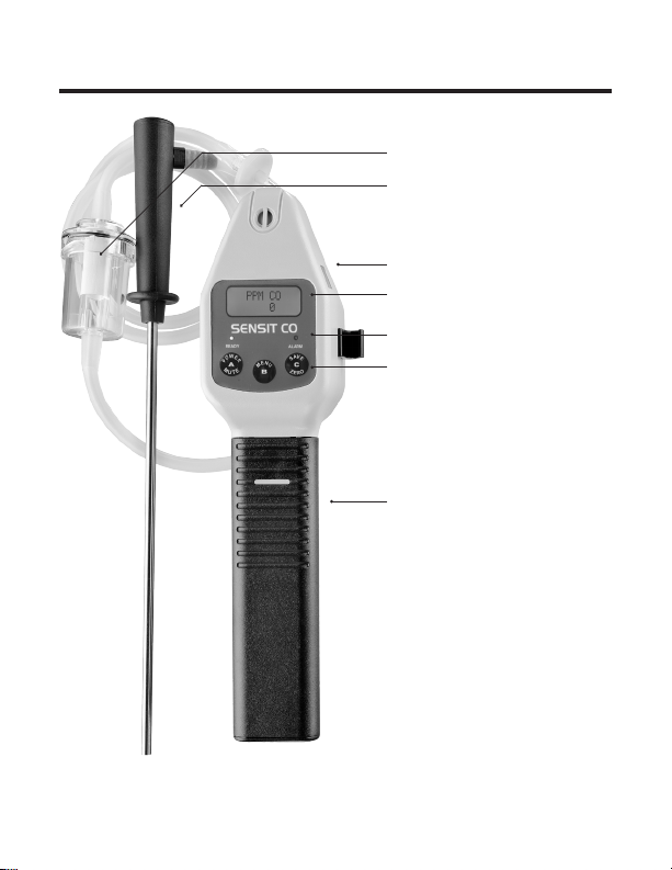
PRODUCT FEATURES
WATER / DIRT FILTER
HOT AIR PROBE
INFRARED COMMUNICATIONS
BACKLIT LCD DISPLAY
ALARM LED
OPERATION BUTTONS
BATTERY COMPARTMENT
8
Find Q uality Pro ducts Onli ne at: sales@ GlobalTestSupp ly.com
www.GlobalTestSupply.com
Page 9

PRODUCT FEATURES
SENSIT® CO instruments are constructed of high impact ABS plastic
to withstand the rigors of eld use. Incorporated in the hand grip area is
the battery compartment.
All SENSIT® CO instruments models operate on “C” type alkaline
batteries or NiMH (nickel metal hydride) batteries. The approved
batteries are, PROCELL MN1400 Alkaline or equivalent and the
PANASONIC HHR300CH NiMH battery or equivalent.
The two line LCD continually updates PPM CO levels for the base
model, percent oxygen level is added for the CO/O2 model and PPM
“CF” is included for the CO/O2/air-free CO model. Regardless of the
model, all instruments display all data simultaneously on the LCD when
in the work display.
All models use a diaphragm pump to draw in the air samples. Flow
block, low battery power and sensor failure alert will appear on the LCD
as needed.
Warning systems for the operator consist of one audible alarm, omitting
a tone from the speaker on the back of the instrument and two visual
indicators on the front. One is a red ashing LED alarm light, the other
is a ashing gas or optional oxygen reading on the LCD when the
instrument detects readings at the alarm set point. All alarms indicate
simultaneously unless the operator chooses to use the audible alarm
mute feature.
An infrared communication window is located on the right side to
permit downloading of calibration data, data saved by the operator
and communication with the Smart-Cal Calibration Station and PCI2s
computer interface.
9
Find Q uality Pro ducts Onli ne at: sales@ GlobalTestSupp ly.com
www.GlobalTestSupply.com
Page 10

PRODUCT FEATURES
There are 3 operational button pads on the front of all models used for
the following features.
BUTTON (A) POWER/MUTE
Turns the instrument ON/OFF, mutes audible alarm, exit menu items.
BUTTON (B) MENU
Enter customer menu.
BUTTON (C) SAVE/ZERO
Save data to on-board memory, manual zero of all sensors, scrolling in
menu options.
10
Find Q uality Pro ducts Onli ne at: sales@ GlobalTestSupp ly.com
www.GlobalTestSupply.com
Page 11

BATTERY INSTALLATION/REPLACEMENT
Battery replacement is necessary when the display reads BAT LOW,
an audible alarm sounds and the green ready LED ashes. When BAT
LOW is displayed, the instrument has approximately 30 minutes of
useful operation time prior to shut off.
⚠ CAUTION: Always change batteries in an environment free of
combustible gases.
Remove the battery sleeve cover by depressing the locking tab on the
front of the handle with a coin or at object and pulling the handle away
from the top or display area of the instrument.
Place 3 approved batteries into the battery holder. For best results hold
the battery compartment so that it lays in your right hand. With your
left hand install the battery that goes toward the front rst. The battery
that is in contact with the rear spring second and nally insert the third
battery in the center by forcing the second battery such that the spring
compresses and allows the batteries to go into place. If you do not
use your right hand to hold the bottom of the battery compartment the
batteries can come out.
Observe the polarity markings on the inside of the battery holder.
Improper installation will cause the instrument not to operate. Replace
the battery sleeve and allow the locking tab to snap into position.
Check to be sure the handle is secure to the instrument body by gently
pulling the handle away. The handle will remain rmly in place if a proper
connection is made.
11
Find Q uality Pro ducts Onli ne at: sales@ GlobalTestSupp ly.com
www.GlobalTestSupply.com
Page 12

OPERATION AND USE
⚠ CAUTION: Always start your SENSIT® CO in a gas free
environment to insure a proper zero.
1. Push the POWER/MUTE BUTTON (A). The following start-up
sequence will be displayed.
a. Product name and model version number
b. System check for proper pump and battery strength
c. Date and time
d. Serial number
e. Warm-up countdown, 10 seconds
f. “Autozero” zeroing all sensors (CO standard, O2 optional)
g. Work display (will vary depending on model version)
2. If the display fails to illuminate or BAT LOW is shown on the display,
replace the batteries. There is room in the carrying case to keep an extra
set.
3. If a sensor is past the intended calibration cycle, CAL DUE will appear
during the start-up sequence. Calibrate the instrument before placing
it in service. If calibration is unsuccessful, remove the instrument from
service and consult the factory.
4. If the instrument detects an inoperable sensor an ERROR message
will ash during the warm-up. The display will also show “FAIL”. Remove
the instrument from service and contact the factory.
12
Find Q uality Pro ducts Onli ne at: sales@ GlobalTestSupp ly.com
www.GlobalTestSupply.com
Page 13

OPERATION AND USE
5. Prior to use, test a running instrument and hot air probe for air leakage.
Air leaks can cause diluted samples, provide inaccurate readings and
invalid tests.
First, block the inlet of the instrument with your nger for approximately
5 seconds. The display should read “FLOW BLOCKED” and a warning
beep will sound if all seals are intact. This is a pass. However, if the ow
block signals are not given, this is a failure and the instrument should be
removed from service. Please consult the factory for repair.
If the instrument passes, attach the hot air probe to the instrument. The
connection need only be nger tight and requires approximately 1/4 turn
of the tting. Next block the end of the probe. Within 10 seconds the
display should read “FLOW BLOCKED” and the audible warning will
sound. ‘This is a pass. However, if the ow block signals are not given,
this is a failure and the probe should be removed from service. Please
consult the factory for repair.
⚠ CAUTION: Do not handle the steel portion of any hot air probe
during or too soon after sampling. It will become hot and retain
heat and burns may occur!
6. When sampling or testing areas with elevated temperatures such
as an appliance vent or ues, always attach and use the supplied hot
air probe. Failure to use the approved probe can result in inaccurate
readings or damage to the instrument and may void the warranty.
13
Find Q uality Pro ducts Onli ne at: sales@ GlobalTestSupp ly.com
www.GlobalTestSupply.com
Page 14

OPERATION AND USE
7. For models with the optional Air-Free CO calculation, the data will
appear on the LCD in the form of PPM next to the “CF” designator. This
calculation will only be presented when the oxygen level has dropped to
18.9% or less while sampling ue gas emissions.
NOTE: Air Free CO levels or CF readings are calculated by the instrument
based on CO and O2 levels detected during ue gas sampling.
8. To disable or enable the audible alarm, press and release the
POWER/MUTE BUTTON (A) .
9. To save any displayed readings, press and release the SAVE/ZERO
BUTTON (C). The data saved can be viewed or downloaded later.
Printouts are possible using the optional IR printer (#870-00004). See
Menu operation for complete instructions.
10. When used in low light conditions, an automatic backlight will
illuminate the display.
11. To turn the instrument off, press and hold the POWER/MUTE
BUTTON (A) for approximately 5 seconds until “Power Down” appears
on the display.
14
Find Q uality Pro ducts Onli ne at: sales@ GlobalTestSupp ly.com
www.GlobalTestSupply.com
Page 15

CALIBRATION CHECK
To verify the accuracy of SENSIT® CO, it must be exposed to a known
concentration of test gas that will test any sensor combination included
in your particular model.
Any sensor that does not meet the specications listed in this manual
may require calibration or repair. A calibration check does not update
the calibration due date. Full calibration is required to update these
times.
A calibration past due message will appear during warm-up if calibration
has not been performed per your instrument setting. Anytime it is
suspected the SENSIT® CO is not working properly, check calibration.
15
Find Q uality Pro ducts Onli ne at: sales@ GlobalTestSupp ly.com
www.GlobalTestSupply.com
Page 16

USER MENU
SENSIT® CO models have several categories within the User Menu:
PRINT MENU:
CALIBRATION:
POWER OFF:
SET CLOCK:
SHOW CAL LOG:
SHOW SES LOG:
BUMP TEST:
SMART-CAL:
O2 TEST:
Print session log (saved data), cal log (calibration
data), access Smart-Cal communication.
Calibrate CO sensor and access Smart-Cal
communication.
Set the automatic shut off timer in minutes.
Set date and time.
Display last valid calibration data.
Display saved sensor reading data with
corresponding date and time.
Perform automatic test for response to minimum
of 80% of 100 ppm CO calibration gas within 45
seconds.
Access automatic Smart-Cal communication.
A 20 second test to conrm depletion of the O2
readings when exposed to the proper gas, such
as 100% methane (only on models with optional
oxygen sensors installed).
16
Find Q uality Pro ducts Onli ne at: sales@ GlobalTestSupp ly.com
www.GlobalTestSupply.com
Page 17

USER MENU OPERATION
PRINT MENU
From the working display access the menu by pressing & holding the
MENU BUTTON (B) until the top line of the display reads USER MENU.
The bottom line will read PRINT MENU. Press & release the MENU
BUTTON (B) once to enter the menu.
Prepare the optional IR printer. Aim the IR window (on the right side of
the instrument) at the IR window on the printer.
Press & release the SAVE/ZERO BUTTON (C) to scroll to the item you
want to print. Press & release the MENU BUTTON (B) to print that item.
To exit this menu, press & release the POWER/MUTE BUTTON (A) until
the instrument returns to the working display.
CALIBRATION
See Calibration section on page 26.
17
Find Q uality Pro ducts Onli ne at: sales@ GlobalTestSupp ly.com
www.GlobalTestSupply.com
Page 18

USER MENU OPERATION
POWER OFF
From the working display access the menu by pressing & holding the
MENU BUTTON (B) until the top line reads USER MENU and the
bottom line will read PRINT MENU.
Press & release the SAVE/ZERO BUTTON (C) until the bottom line
displays POWER OFF. Press & release the MENU BUTTON (B) once
to enter the menu.
Press & release the MENU BUTTON (B) to decrease the minutes until
automatic shut-off or press & release the SAVE/ZERO BUTTON (C) to
increase the minutes.
NOTE: Setting this number to “0” will set the instrument to run
continuously for as long as the battery power will permit.
Press & release the POWER/MUTE BUTTON (A) to save the selection.
To exit this menu, press & release the POWER/MUTE BUTTON (A)
once more.
18
Find Q uality Pro ducts Onli ne at: sales@ GlobalTestSupp ly.com
www.GlobalTestSupply.com
Page 19

USER MENU OPERATION
SET CLOCK
From the working display access the menu by pressing and holding
the MENU BUTTON (B) until the top line reads USER MENU and the
bottom reads PRINT MENU.
Press & release the SAVE/ZERO BUTTON (C) until the bottom line
displays SET CLOCK. Press & release the MENU BUTTON (B) once
to enter the menu.
The day will be the section ashing on the display. To change this
section, press & release the MENU BUTTON (B) for adjustments. Press
& release the SAVE/ZERO BUTTON (C) to advance to the next section
(month, year or time).
Press & release the POWER/MUTE BUTTON (A) to save the selection.
To exit this menu, press & release the POWER MUTE BUTTON (A).
19
Find Q uality Pro ducts Onli ne at: sales@ GlobalTestSupp ly.com
www.GlobalTestSupply.com
Page 20

USER MENU OPERATION
SHOW A CALIBRATION LOG
From the working display press & hold the MENU BUTTON (B) until the
top line reads USER MENU, the bottom line reads PRINT MENU.
Press & release the SAVE/ZERO BUTTON (C) to scroll until the bottom
line reads SHOW CAL LOG. Press & release the MENU BUTTON (B)
once to enter the menu.
Calibration data will be displayed. The sensor which was calibrated will
appear on the top line and the date of the last successful calibration will
appear on the bottom line.
Press & release the SAVE/ZERO BUTTON (C) to scroll to view the next
available sensor calibration data. After viewing the calibration data for
the last sensor, the next scroll will return the display to the USER MENU.
To exit this menu, press & release the POWER/MUTE BUTTON (A).
PRINT A CALIBRATION LOG
From the working display, press & hold the MENU BUTTON (B) until
the top line reads USER MENU, the bottom line reads PRINT MENU.
Press & release the MENU BUTTON (B) once to enter the menu. Press
& release the SAVE/ZERO BUTTON (C) to scroll until the bottom line
reads CAL LOG.
Prepare the optional IR printer. Aim the IR window on the right side of
the instrument at the IR printer. Press & release the MENU BUTTON (B)
to print the log. To exit this menu, press & release the POWER/MUTE
BUTTON (A) to return to working display.
20
Find Q uality Pro ducts Onli ne at: sales@ GlobalTestSupp ly.com
www.GlobalTestSupply.com
Page 21

USER MENU OPERATION
SHOW A SESSION LOG
From the working display, press & hold the MENU BUTTON (B) until the
top line reads USER MENU and the bottom line reads PRINT MENU.
Press & release the SAVE/ZERO BUTTON (C) to scroll until the bottom
line reads SHOW SES LOG. Press & release the MENU BUTTON (B)
once to enter the menu.
SESSION 1 will be displayed. This is the most recent data saved. Press
& release the SAVE/ZERO BUTTON (C) to scroll to the session number
you want to view.
Press & release the MENU BUTTON (B) once to enter that session’s
recorded day, month and time. Press & release the MENU BUTTON (B)
once again to access the gas readings for that session.
Press & release the SAVE/ZERO BUTTON (C) to scroll to view the
individual gas readings saved. Press & release the POWER/MUTE
BUTTON (A) once to access a different session number.
Press & release the SAVE/ZERO BUTTON (C) to scroll to a new
session number. The standard number of available stored sessions is
factory set at 6 but is factory adjustable up to 100.
To exit this menu, press & release the POWER/MUTE BUTTON (A) to
return to the working display.
21
Find Q uality Pro ducts Onli ne at: sales@ GlobalTestSupp ly.com
www.GlobalTestSupply.com
Page 22

USER MENU OPERATION
PRINT A SESSION LOG
From the working display, press & hold the MENU BUTTON (B) until the
top line reads USER MENU and the bottom line reads PRINT MENU.
Press & release the MENU BUTTON (B) once to enter this menu,
SESSION LOG will be displayed.
Prepare the optional IR printer. Aim the IR window, on the right side of
the instrument, at the IR printer. Press & release the MENU BUTTON
(B) to print the log.
Press & release the POWER/MUTE BUTTON (A) to return to the
working display.
22
Find Q uality Pro ducts Onli ne at: sales@ GlobalTestSupp ly.com
www.GlobalTestSupply.com
Page 23

USER MENU OPERATION
BUMP TEST
From the working display, press & hold the MENU BUTTON (B) until the
top line reads USER MENU and bottom line reads PRINT MENU.
Press & release the SAVE/ZERO BUTTON (C) to scroll until the bottom
line reads BUMP TEST.
Prepare the appropriate certied gas mixture for your instrument model
(see proper gas mixtures listed in the Calibration section).
Apply the gas to the instrument and press & release the MENU BUTTON
(B) to start the BUMP TEST. The display will show the gas value being
tested on the top line with registered gas value and a 45-60 second
countdown on the bottom line. The instrument will automatically check
the function of the CO sensor.
If sensor tested reads at least 80% of the value of the gas, within the
time period required, the display will ash BUMP TEST PASS before
returning to the USER MENU automatically. Press & release the
POWER/MUTE BUTTON (A) to exit and return to the working display.
If any sensor fails, the display will show BUMP TEST FAILED. This
means that calibration is required. If calibration is unsuccessful, remove
the instrument from service.
Consult the factory in the event of any failure. To exit this menu, press
& release the POWER/MUTE BUTTON (A) to return to the working
display.
23
Find Q uality Pro ducts Onli ne at: sales@ GlobalTestSupp ly.com
www.GlobalTestSupply.com
Page 24

USER MENU OPERATION
SMART-CAL
From the working display, press & hold the MENU BUTTON (B) until the top
line reads USER MENU and the bottom line reads PRINT MENU. Press &
release the SAVE/ZERO BUTTON (C) to scroll until the bottom line reads
SMART CAL.
Place the instrument into the cradle on the left side of the Smart-Cal Calibration
Station. Attach the tubing from the station to the instrument. Press & release
the MENU BUTTON (B), the display will show SMART CAL communicating.
Press & release the CALIBRATE button on the Smart -Cal and calibration
will begin automatically. If successful, CALIBRATION PASSED will show on
display.
If unsuccessful, CALIBRATION FAILED will show. Let the instrument clear
and repeat the calibration process. If the instrument will not pass, remove the
instrument from service. Consult the factory in the event of any failure.
Alternative methods to enter the Smart-Cal menu are:
1. Enter the USER MENU. Press & release the MENU BUTTON (B)
once to enter the PRINT menu.
Press & release the SAVE/ZERO BUTTON (C), to scroll until the bottom
line reads SMART-CAL. Press & release the MENU BUTTON (B) once
to begin Smart-Cal communication.
2. From the working display, press & hold the POWER/MUTE BUTTON
(A) for 2-3 seconds. The display will read SMART CAL communicating.
24
Find Q uality Pro ducts Onli ne at: sales@ GlobalTestSupp ly.com
www.GlobalTestSupply.com
Page 25

USER MENU OPERATION
O2 TEST
From the working display press & hold the MENU BUTTON (B) until the
top line reads USER MENU and the bottom line reads PRINT MENU.
Press & release the SAVE/ZERO BUTTON (C) to scroll until the bottom
line reads O2 TEST.
Apply recommended gas mixture void of oxygen, such as 100%
Methane or 100% Nitrogen and press & release the MENU BUTTON
(B) to start the test. A 20 second countdown will begin.
If the sensor shows proper depletion within this period, PASSED will
ash on the display. Press & release the POWER/MUTE BUTTON (A)
to return to the working display.
If the O2 sensor does not respond properly within the 20 second test,
FAILED will appear on the display. Remove the instrument from service.
Consult the factory in the event of any failure.
Press & release the POWER/MUTE BUTTON (A) to return to the
working display.
25
Find Q uality Pro ducts Onli ne at: sales@ GlobalTestSupp ly.com
www.GlobalTestSupply.com
Page 26

CALIBRATION
Calibration is the process of setting the readings of the sensors in the
instrument to equal the value of certied calibration gases. Prior to
calibration, allow the instrument to operate for 5 minutes in a clean air
environment and conduct a manual zero of the instrument using the
SAVE/ZERO (C) button.
NOTE: Using calibration kits other than recommended by SENSIT
TECHNOLOGIES may cause inaccurate readings. Repairs are required
if any sensor fails to calibrate. Consult SENSIT TECHNOLOGIES for
details.
NOTE: When calibrating, the numbers shown on the display represent
the numbers seen by the microprocessor and should not be confused
with actual gas readings. These readings will update every 5 seconds
during calibration.
26
Find Q uality Pro ducts Onli ne at: sales@ GlobalTestSupp ly.com
www.GlobalTestSupply.com
Page 27

CALIBRATION
The following instructions pertain to manual calibration of the Sensit CO
models. If you are using the automatic Smart-Cal Calibration Station,
the procedure is different. See the Smart-Cal sections of this manual or
consult the Smart-Cal instruction manual.
CARBON MONOXIDE (CO) CALIBRATION (100PPM CO/AIR)
From the working display press & hold the MENU BUTTON (B) until the
top line reads USER MENU.
Press & release the SAVE/ZERO BUTTON (C) once. The bottom line
will read CALIBRATION.
Press & release the MENU BUTTON (B) once. The bottom line will read
CO 100ppm. Apply 100ppm CO/Air calibration gas and press & release
the MENU BUTTON (B) to start CO calibration.
When the reading is satisfactory, the display will ash DATA SAVED
indicating that calibration is complete for that sensor. The date for CAL
PAST DUE is automatically reset for that sensor as well.
Scroll with the SAVE/ZERO BUTTON (C) if you need to calibrate another
sensor. When nished, remove and shut off the gas supply. Press &
release the POWER/MUTE BUTTON (A) to return to the working display.
27
Find Q uality Pro ducts Onli ne at: sales@ GlobalTestSupp ly.com
www.GlobalTestSupply.com
Page 28

CALIBRATION
OXYGEN SENSOR TEST
To determine if the O2 sensor is working properly, verify the sensors
reaction by exposing it to a calibration gas void of oxygen, such as 100%
methane or 100% nitrogen.
From the working display press & hold the MENU BUTTON (B) until the
top line reads USER MENU. Scroll with SAVE/ZERO BUTTON (C) until
the bottom line reads O2 TEST.
Apply proper gas and press & release the MENU BUTTON (B) to start
the test. A 20 second countdown will begin. If the sensor shows proper
depletion within this period, PASSED will ash on the display. Press &
release the POWER/MUTE BUTTON (A) to return to the working display.
If the O2 sensor does not respond properly within the 20 second test,
FAILED will appear on the display.
Consult the factory in the event of any failure. Press & release the
POWER/MUTE BUTTON (A) to return to the working display.
NOTE: A calibration failure is indicated on the display by BAD CAL.
Re-calibration should be attempted. Any instrument that does not accept
calibration should be taken out of service. Please contact SENSIT
TECHNOLOGIES for any needed repairs.
28
Find Q uality Pro ducts Onli ne at: sales@ GlobalTestSupp ly.com
www.GlobalTestSupply.com
Page 29

SMART-CAL CALIBRATION
USING THE SMART-CAL CALIBRATION STATION
From the working display press & hold the MENU BUTTON (B) until the
top line reads USER MENU. Scroll with SAVE/ZERO BUTTON (C) until
the bottom line reads SMART CAL.
Place the instrument into the cradle on the left side of the Smart-Cal
Calibration Station. Attach the tubing from the station to the instrument.
Press & release the MENU BUTTON (B), the display will show SMART
CAL communicating. Press & release the CALIBRATE Button on the
Smart-Cal and calibration will begin automatically.
If successful, CALIBRATION PASSED will be displayed on the
instrument. If unsuccessful, CALIBRATION FAILED will show. Let the
instrument clear and repeat the calibration process. If the instrument will
not pass, remove the instrument from service. Consult the factory in the
event of any failure.
Alternative methods to enter the Smart Cal menu are:
1. Enter the USER MENU. Press & release the MENU BUTTON (B) once
to enter the PRINT menu. Press & release the SAVE/ZERO BUTTON
(C) to scroll until the bottom line reads SMART CAL. Press & release
the MENU BUTTON (B) once to begin Smart Cal communication.
2. From the working display, press & hold the POWER/MUTE BUTTON
(A) for 2-3 seconds. The display will read SMART CAL communicating.
Please see the Smart-Cal Calibration Station instruction manual for
additional information.
29
Find Q uality Pro ducts Onli ne at: sales@ GlobalTestSupp ly.com
www.GlobalTestSupply.com
Page 30

NOTES
________________________________________________________
________________________________________________________
________________________________________________________
________________________________________________________
________________________________________________________
________________________________________________________
________________________________________________________
________________________________________________________
________________________________________________________
________________________________________________________
________________________________________________________
________________________________________________________
________________________________________________________
________________________________________________________
________________________________________________________
________________________________________________________
30
Find Q uality Pro ducts Onli ne at: sales@ GlobalTestSupp ly.com
www.GlobalTestSupply.com
Page 31

NOTES
________________________________________________________
________________________________________________________
________________________________________________________
________________________________________________________
________________________________________________________
________________________________________________________
________________________________________________________
________________________________________________________
________________________________________________________
________________________________________________________
________________________________________________________
________________________________________________________
________________________________________________________
________________________________________________________
________________________________________________________
________________________________________________________
31
Find Q uality Pro ducts Onli ne at: sales@ GlobalTestSupp ly.com
www.GlobalTestSupply.com
Page 32

WARRANTY
Your SENSIT® CO is warranted to be free from defects in materials
and workmanship for a period of two years after purchase (excluding
calibration and batteries). If within the warranty period, your instrument
should become inoperative from such defects, the unit will be repaired
or replaced at our option. This warranty covers normal use and does
not cover damage which occurs in shipment or failure which results from
alteration, tampering, accident, misuse, abuse, neglect or improper
maintenance. Proof of purchase may be required before warranty is
rendered. Units out of warranty will be repaired for a service charge.
Internal repair or maintenance must be completed by a SENSIT
TECHNOLOGIES authorized technician. Violation will void warranty.
Units must be returned postpaid, insured and to the attention of the
Service Dept. for warranty or repair.
This warranty gives you specic legal rights and you may have other
rights which vary from state to state.
SENSIT Technologies
851 Transport Drive
Valparaiso, IN 46383
SENSIT CO Instruction Manual
Part # 750-00013
Find Q uality Pro ducts Onli ne at: sales@ GlobalTestSupp ly.com
www.GlobalTestSupply.com
Revision 7-1-2015
 Loading...