

Page 1
TM
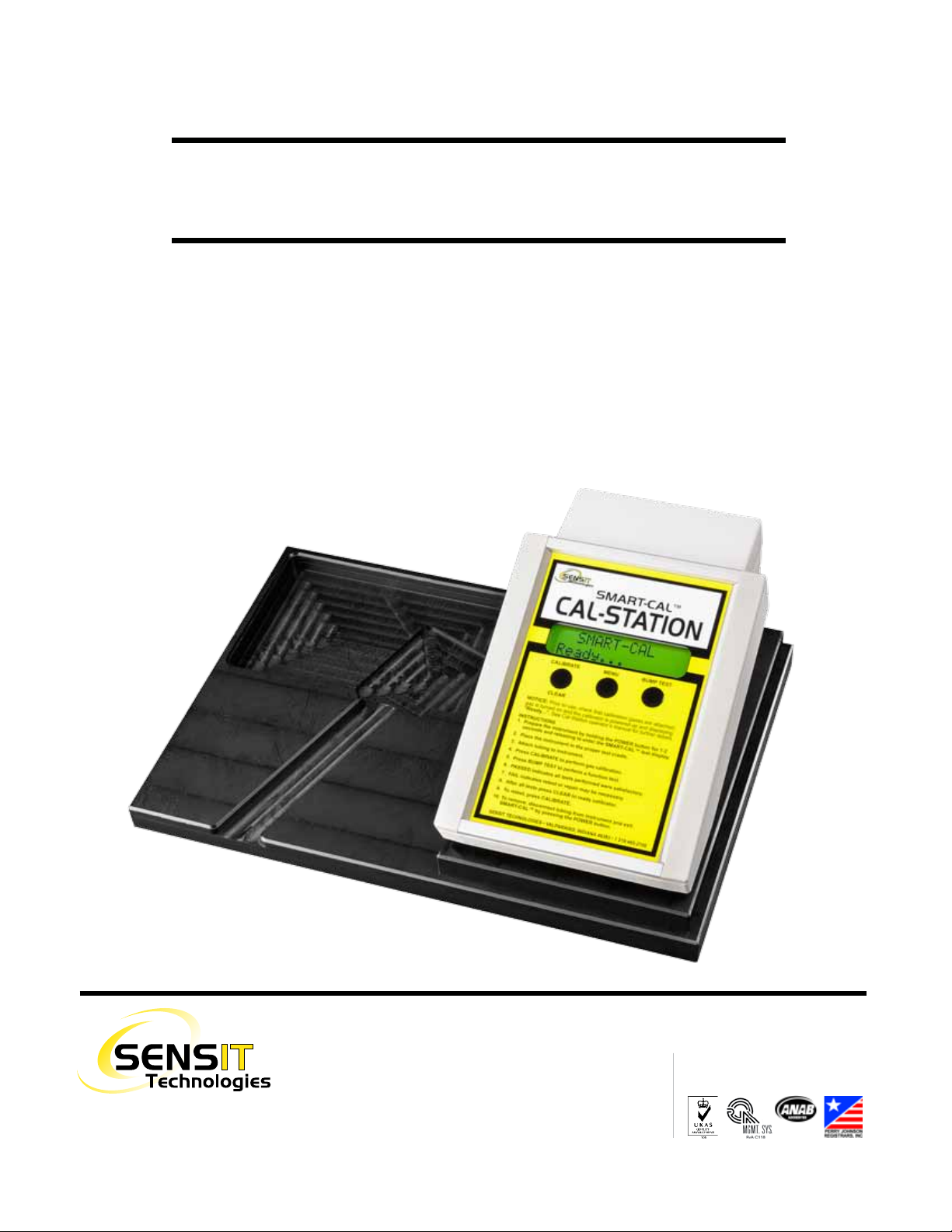
SMART-CAL
CALIBRATION STATION
OPERATION MANUAL
MADE IN USA
SENSIT Technologies
is in compliance with ISO 9001:2008
Find Quality Products Online at: [email protected]
www.GlobalTestSupply.com
Page 2
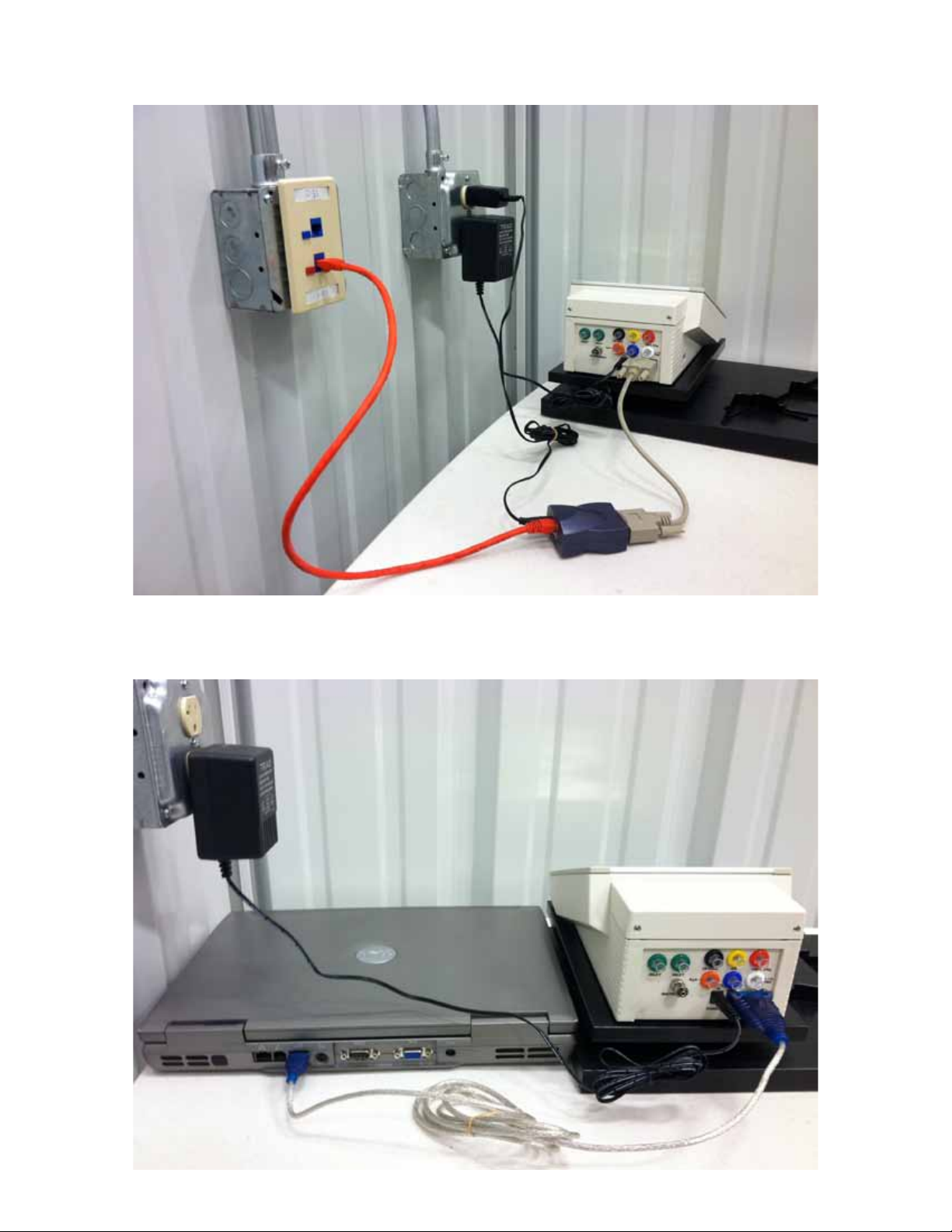
SMART-CAL Station Set-up for SCal-N
SMART-CAL Station Set-up for SCal-D
Find Quality Products Online at: [email protected]
www.GlobalTestSupply.com
Page 3

SENSIT TECHNOLOGIES
Smart-Cal™ Calibration Station Operation Manual
Product Description-Smart Cal Station
The Smart-Cal™ Calibration Station performs automated calibration and record keeping for Sensit®
HXG-3/3P, Sensit® Gold Series, Sensit® PMD and Trak®-It III Series Instruments. The calibrator
communicates with those instruments that have the required two-way infrared communication link.
Instruments that have this feature have a window on the right side of the housing. The Smart-Cal™
calibrator will calibrate all instrument sensors, reset the instrument clock, perform a pump flow
block test, allow review of the data on screen and perform bump tests. The calibrator can be used as
a stand-alone device or with SCal-D™ and SCal-N™ data management software. See Software Setup section for specific requirements and instructions. The on-board memory can store up to 2450
records.
Product Description-SCal-D™ / SCal-N™ Data Management Software
The Data Management Software must be loaded onto a computer. This software is Windows® based
and is compatible with Windows® XP, Windows® 7, Windows® 8 and Windows® 8.1. When the
computer receives the information from the calibrator the data is sorted and stored. Various reports
and alerts can be printed, e-mailed or just stored to automatically alert operators and supervisors of
important data.
Specifications
Size (LxWxH): 10.75” x 6.75” x 4.5”
Weight (Lbs): 2.5
Operating Temperature: 32-120° F
Gas Connection-input: ¼ turn female luer
Gas Connection-output: ¼ turn male luer
Maximum pressure-input: 10 PSIG
Maximum gas-type inputs: 7
Maximum air-type inputs: 1
Standard Accessories
Calibrator Base w/cradle cut outs
110vac power adapter
Single line input (1/8” tubing - 5’ long) with “Y(s)” to attach LEL, CO and H2S connections.
Single line input (3/16” tubing – 5’ long) for 100% methane or propane connection.
Single line input 1/8” tubing 2’ long with luer adapter for clean air below or away from station
Instrument connection tubing with Luer adapter (24”)
Instruction Manual
Data Management Software on CD (SCal-D™ or SCal-N™)
For SCal-D™ - Serial to USB Converter
For SCal-N™ - Serial to Ethernet Device
Accessories
20 PSI regulator w/4’tubing and male luer connection
Demand-style regulators
221 Liter cylinder/regulator adapter
12vdc power outlet adapter
SMART-CAL OPERATION MANUAL • VERSION 18
Find Quality Products Online at: [email protected]
www.GlobalTestSupply.com
1
Page 4
SENSIT TECHNOLOGIES
Hardware Set-up
Attach the appropriate gases to the gas sources. Inlet pressure must be no greater than 20PSI from
any gas source. Combination gas bottles can be attached with the use of “T’s” and/or “Y’s” to attach
to the various gas inputs. During the bump test only the LEL valve will open. It is therefore required
to use “T’s” and or “Y’s” to connect a single gas bottle containing multiple gases if the bump test
operation is used. Each of the connections is color-coded and has a female style luer. Be sure to
check for gas tight connections.
a. Green = Air
b. Purple = 10 PPM HCN/Bal N2
c. Black = LEL
d. Yellow = CO
e. Orange = H2S
f. Red = 100% Methane
g. Blue = 0.1% Methane/Balance N2
h. White = 1.1% Propane
i. Instrument connection is stainless steel and is a male luer (opposite of gas
connections).
Danger Fire or explosion risk from Flammable Gases that may be present. Do not use
near spark or open flame.
Caution To prevent accidental leakage always shut off the gas supply to calibrator when
not in use.
Plug the wall adapter into a 110vac with 1000ma output or greater or the valves will not operate (A
cigarette lighter adapter can be used to supply 12vdc directly to the calibrator). Insert the power plug
into the power receptacle on the back of the Calibrator. The Calibrator will now automatically
power on.
Start Up
“SMART-CAL™” will be displayed on the top line and “Version X.XX” on the bottom line for 2
seconds. Serial number will be displayed on the bottom line for 2 seconds. “Date” on the top line and
the “Time” on the bottom line for 2 seconds. “SMART-CAL™” will be displayed on the top line
and “Ready…” on the bottom line continuous (this is the ready position). Display is always backlit.
2
Find Quality Products Online at: [email protected]
SMART-CAL OPERATION MANUAL • VERSION 18
www.GlobalTestSupply.com
Page 5
SENSIT TECHNOLOGIES
Operational Buttons
The Smart-Cal Station has a three button operation. The Left Button is to start the calibration process
(Calibrate) or to return to the “Ready…” display (Clear) after the previous instrument has been
tested. The Right button is the Bump Test. This allows the operator to test the instrument between
calibrations for proper operation. This will test the current calibration readings in the instrument
memory against the sample gas. If the instrument readings are within 20% of the last calibration
numbers the bump test is a pass. If they are not, “Fail” will appear on the screen and calibration is
required. The Center button is the Menu button. From here you can review the test log, erase the
memory and set the clock. To enter the menu, hold the MENU button for 5-6 seconds to access the
options. This function is password protected.
Performing Calibration
Prepare the instrument by powering on the instrument followed by pressing the power button for 2-3
seconds and releasing until “Smart-Cal Communicating” is displayed on the instrument. Next place
the instrument into the proper position of the cradle and attach the instrument hose to the proper
location on the instrument. Press the left button and calibrator will display “Searching” for the
instrument. If the instrument is communicating to the calibrator the process will continue.
Caution Only place one instrument at a time in the Smart-Cal™ mode within 4 feet of
the Smart-Cal™ Calibrator.
After an instrument begins communicating (“Searching”) with the calibrator, the display on the
calibrator will read “Device Found”. Next it will display the brand of instrument (i.e. Sensit or TrakIt) and its serial number. The version number of the instrument will automatically determine what
gases should be calibrated. If the instrument and the calibrator do not communicate within 15
seconds press the “Calibrate/Clear” button on the calibrator. “IR Failed” will be displayed. Place the
instrument in the working display, access the Smart-Cal feature and retry. If unsuccessful the
instrument or calibrator may need service. Try another instrument to confirm calibrator is working.
Contact manufacturer with any questions.
Testing will take place in the following order:
1. The calibrator will automatically reset the date and time of the instrument it is testing. This
creates consistency for record keeping purposes.
2. “Autozero” to test the pump flow block and sensors for proper zero reading. Display will
read “FAIL” followed by the type of sensor failed such as Pump Flow, LEL, NAT, PRO, O2,
CO or H2S on the calibrator if any specifications are not met. Calibration cannot occur if any
of these have failed. If this has failed the display will read “Autozero Fail” on the top line
and sensor type on the bottom Line. This should remain on the display until the left button is
pressed again at which point “Ready…” will show on the display. Pump flow is checked by
all internal valves closing, instrument pump runs and looks for flow block parameters.
Multiple sensor failures are displayed individually for 1-2 seconds each. If any of these
failures occur the instrument will display “Calibration Failed” on its display. Pressing the left
button two times will restart the calibration process.
3. The calibrator will automatically apply the gases to the instrument. Calibration occurs in the
following order as the gases are required: 50% LEL Methane, CO, H2S, 100% methane or
SMART-CAL OPERATION MANUAL • VERSION 18
Find Quality Products Online at: [email protected]
www.GlobalTestSupply.com
3
Page 6

SENSIT TECHNOLOGIES
50%LEL propane. The instrument will only calibrate to the gas it is set to in the case of
methane or propane. If the instrument is set to “NAT” the calibrator will not calibrate
propane and vise versa.
4. At the end of the calibration process for each gas (approximately 15 to 120 seconds for each
gas) the calibrator will display “PASSED” or “FAIL”.
5. At the end of the completed calibration if any sensor has failed the calibrator will display
“SN XXXXX” CAL FAIL” on the top line and the type of gas failed on the bottom. Pressing
the left button (CLEAR) will clear the display and default to the “Ready…” position.
6. The instrument will now allow the pump to operate and purge the sensors of any gas. Press
the power button two times to go to the working display.
Performing a Bump Test
To perform a bump test the instrument must be in the “Smart-Cal Communicating” mode. Pressing
the right button will begin the process of testing LEL, CO, H2S (or combination required) sensors by
applying the necessary gases (as determined by the instrument model number) for up to 30 seconds
while looking for an instrument reading of at least 80% of the calibrated value. During the process
the calibrator will display “Bump Test” on the top line and “TESTING…” on the bottom line.
Autozero, will be done first, followed by CO, LEL, and finally H2S. 100% gas volumes are not
tested during this operation.
If at the end of the Bump Test any gas has failed the display will read “Bump Test FAIL” on the top
line and list the sensor type that failed on the Bottom line. Multiple sensor failures are displayed
individually for 1-2 seconds each. Pressing the left button will return to the ready position. Pressing
the left button one more time will start the calibration process. It is not necessary to change anything
on the instrument at this time.
When no fail occurs then the calibration display will show “Bump Test Passed” on the top line and
Serial Number on the bottom line and automatically return to the ready position.
The User Menu
To access the user options hold the MENU button for 5-6 seconds. This is password protected.
When the password is needed advance the displayed number (1000) by pressing the right button to
1122. Use the center button to reduce the number. The left button enters the number. If you do not
put in the correct password the display will show “PASSWORD” on the top line and “FAILED” on
the bottom line. It is necessary to press the MENU button for 5-6 seconds and attempt entering the
password again.
After successfully entering the password the various menu items can be reviewed. At this time the
top line will display “User Menu”. The bottom line will display various options including
Time/Date, Clock Set, and Review. Use the right bump test button to view the various options. Press
the center button to access that option.
4
Find Quality Products Online at: [email protected]
SMART-CAL OPERATION MANUAL • VERSION 18
www.GlobalTestSupply.com
Page 7

SENSIT TECHNOLOGIES
Clock set allows the adjustment of the date and time of the calibrator. Press the center button. The
Day will flash. Use the center button to advance the number or month of the flashing location. Use
the right button to advance to the next location to change. Use the left button to save the changes and
return to the USER MENU. Pressing the left button two more times returns you to the ready
position.
Review allows you to view the activities at this calibrator on the dates it was used. Press the center
button to enter a particular date. Use the right button to scroll through the various serial numbers and
test results for those serial numbers on that date. Use the left button to go back to the dates. Pressing
the left button again gets you back to the User Menu. Pressing two more times puts the calibrator in
the ready position.
Warranty
The Smart-Cal™ Calibration Station has a two-year limited warranty for defects in materials and
workmanship. If within the warranty period the Smart Cal Calibration Station fails to operate from
such defects return it postage paid to the address below. It will be repaired or returned at our option.
This warranty covers normal use and does not cover damage which may arise from alteration,
tampering, misuse, abuse, neglect or improper maintenance. SENSIT TECHNOLOGIES is not liable
for lost data due to malfunction of Smart-Cal Calibration Station. Proof of purchase may be required
before warranty is rendered.
Shipping Address
SENSIT TECHNOLOGIES
851 Transport Drive
Valparaiso, IN 46383
This warranty gives you specific legal rights, and you may also have other rights that vary from state
to state.
SENSIT TECHNOLOGIES - Smart-Cal Calibration Station Manual 1/2012 V18
SMART-CAL OPERATION MANUAL • VERSION 18
5
Find Quality Products Online at: [email protected]
www.GlobalTestSupply.com
Page 8

 Loading...