

Page 1
Sigfox_RCZ2 Installation
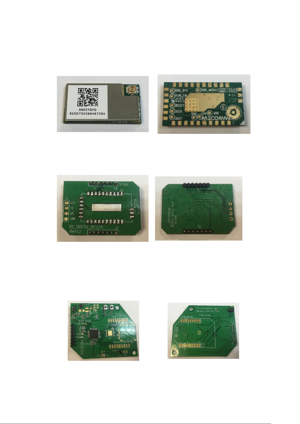
1. RCZ2_Module Top and Bottom side following Fig.1.
Fig.1 RCZ24 Module schematic diagram
2. TR_SIGFOX_RCZ24 carrier board following Fig.2.
Fig.2 TR_SIGFOX_RCZ24 carrier board schematic diagram
3. TR_EVERDAY Control Board Top and Bottom side following
Fig.3.
Fig.3 TR_EVERDAY PCB schematic diagram
Page 2
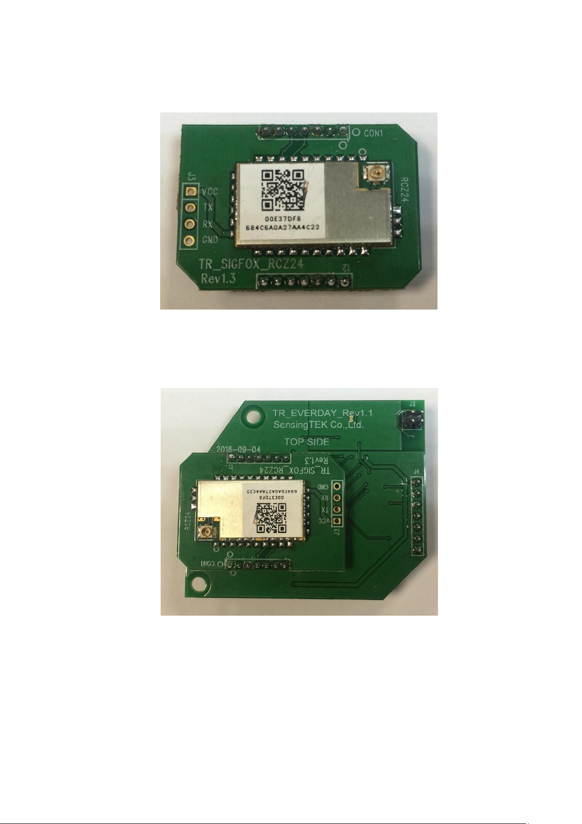
4. Solder the module on the carrier board.
Fig.4 Module_Sigfox_RCZ2 on the carrier board
5. Solder carrier board on the TR_EVERDAY Control Board.
Fig.5 Module_Sigfox_RCZ2 hardware installation diagram
Page 3
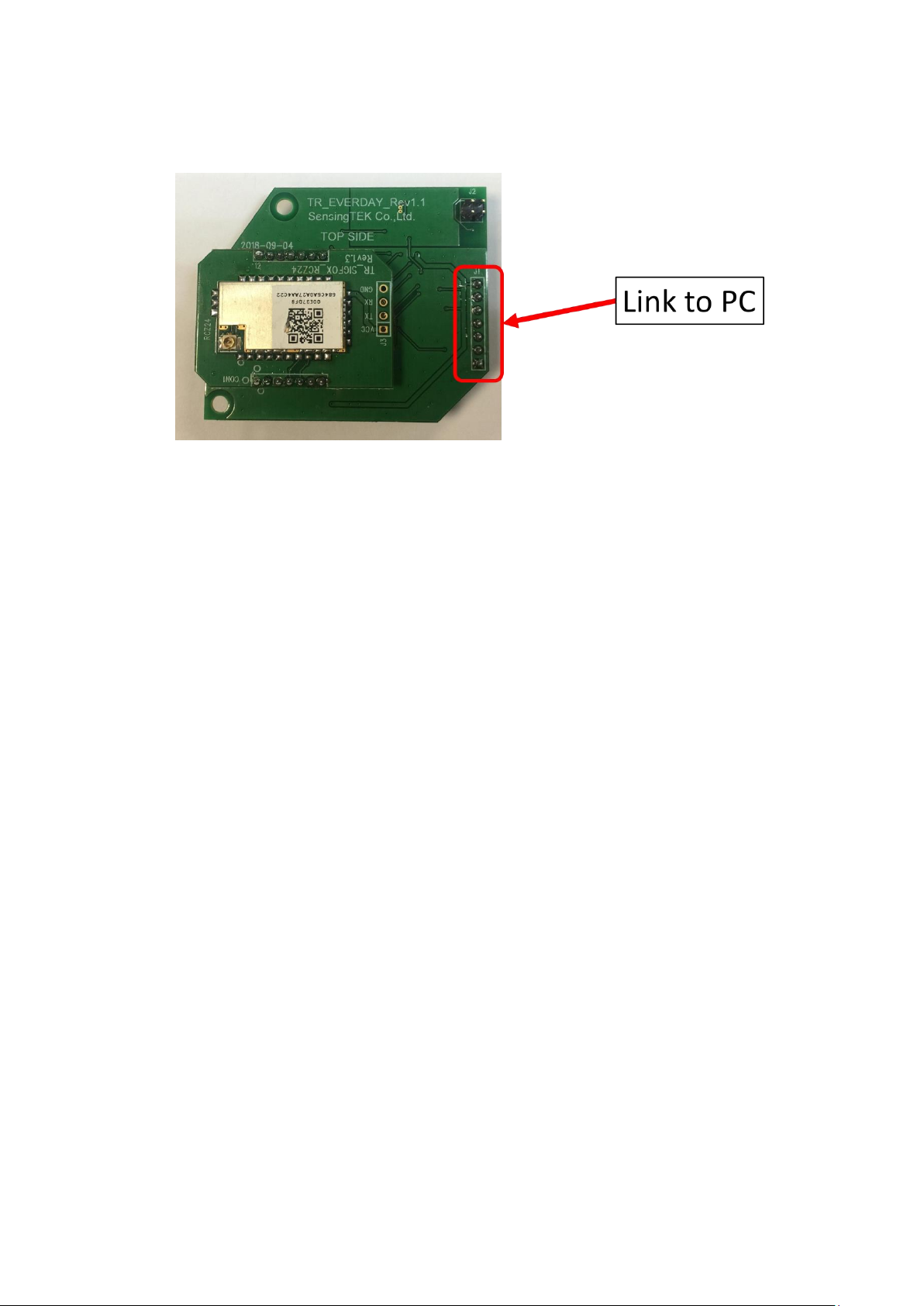
6. Burn software to control board following Fig.6.
Fig.6 Module_Sigfox_RCZ2 software installation diagram
Page 4

Federal Communication Commission Interference Statement
This device complies with Part 15 of the FCC Rules. Operation is subject to the
following two conditions: (1) This device may not cause harmful interference, and (2)
this device must accept any interference received, including interference that may cause
undesired operation.
This equipment has been tested and found to comply with the limits for a Class B
digital device, pursuant to Part 15 of the FCC Rules. These limits are designed to
provide reasonable protection against harmful interference in a residential installation.
This equipment generates, uses and can radiate radio frequency energy and, if not
installed and used in accordance with the instructions, may cause harmful interference
to radio communications. However, there is no guarantee that interference will not
occur in a particular installation. If this equipment does cause harmful interference to
radio or television reception, which can be determined by turning the equipment off and
on, the user is encouraged to try to correct the interference by one of the following
measures:
- Reorient or relocate the receiving antenna.
- Increase the separation between the equipment and receiver.
- Connect the equipment into an outlet on a circuit different from that
to which the receiver is connected.
- Consult the dealer or an experienced radio/TV technician for help.
FCC Caution: Any changes or modifications not expressly approved by the party
responsible for compliance could void the user's authority to operate this equipment.
This transmitter must not be co-located or operating in conjunction with any other
antenna or transmitter.
Radiation Exposure Statement:
This equipment complies with FCC radiation exposure limits set forth for an
uncontrolled environment. This equipment should be installed and operated with
minimum distance 20cm between the radiator & your body.
Page 5

This device is intended only for OEM integrators under the following conditions:
1) The antenna must be installed such that 20 cm is maintained between the antenna
and users, and
2) The transmitter module may not be co-located with any other transmitter or
antenna.
As long as 2 conditions above are met, further transmitter test will not be required.
However, the OEM integrator is still responsible for testing their end-product for any
additional compliance requirements required with this module installed
IMPORTANT NOTE:
In the event that these conditions can not be met (for example certain laptop
configurations or co-location with another transmitter), then the FCC authorization is
no longer considered valid and the FCC ID can not be used on the final product. In
these circumstances, the OEM integrator will be responsible for re-evaluating the end
product (including the transmitter) and obtaining a separate FCC authorization.
End Product Labeling
This transmitter module is authorized only for use in device where the antenna may be
installed such that 20 cm may be maintained between the antenna and users. The final
end product must be labeled in a visible area with the following: “Contains FCC ID:
2AE2VRCZ2”. The grantee's FCC ID can be used only when all FCC compliance
requirements are met.
Manual Information To the End User
The OEM integrator has to be aware not to provide information to the end user
regarding how to install or remove this RF module in the user’s manual of the end
product which integrates this module.
The end user manual shall include all required regulatory information/warning as show
in this manual.
The antenna provided to the EUT, please refer to the following table
Antenna Net Gain(dBi)
1.17
Frequency Range
902.137~904.662 MHz
Antenna Type
FPC
Connector Type
IPEX -MHF4
 Loading...