

Sensear SM1P,SM1B,SM1P IS,SM1B IS User Manual

SM1P/B
MANUAL
ENGLISH


DOC00084 SM1P/B Manual rev 12.00
1
English
INTRODUCTION
The SM1P/B is a state of the art hearing protection (ie protects against
harmful noise) communication system that allows you to retain
situational awareness whilst remaining in full contact with your team via
Short Range technology, as well as two-way radio or cellular device via
Bluetooth® or wired connection.
There are Intrinsically Safe variants of the product (“IS” and “Ex”) that
meet international standards for use in explosive gas environments.
Please see ratings on page 37 and 38.
Situational awareness is provided by processing technology and
environmental microphones mounted within the headset.
Contact through two-way radios is enabled by the SRCK6XXXXX* cable
assembly available separately. Cable numbers vary depending on the
two-way radio model. Please consult with the website for more
information.
*SRCK6XXXXX part numbers vary depending on the radio connector.
Consult your supplier for the appropriate cable.
For language translated manuals and further information, please refer
to the website.

DOC00084 SM1P/B Manual rev 12.00
2
English
MAINTENANCE AND SAFETY INSTRUCTIONS
The SM1P/B IS and Ex has been designed such that minimal user
maintenance is required. Only those parts listed on page 21 of this
instruction manual are user replaceable.
SPECIFIC CONDITIONS OF USE Potential Electrostatic hazard, clean
with damp cloth only.
WARNING The IS/Ex headset must not be disassembled. In the event of
a malfunction the unit should be switched off and returned to Sensear
Pty Ltd. The battery is not user replaceable; the IS/Ex headset must be
returned to Sensear for battery replacement. Substitution of
components may impair Intrinsic Safety.
WARNING Connection to the USB Connector located in the connector
compartment of the right-hand ear-cup is not permitted. The USB is for
service only.
WARNING The IS/Ex headset must not be charged in a hazardous
area. The battery shall only be charged when the equipment is located in
a safe area using the class II charging supply via the jack socket on the
left-hand ear cup; the maximum permitted voltage at this charging input
is Um = 6V.
WARNING Connection to the multi-pin hirose connector of the IS/Ex
headset (wired version) shall only be done via an SRCK6XXXXX IS/Ex
headset Intrinsically Safe interface cable. No direct connection to the
multi-pin hirose connector is permitted.
DOC00084 SM1P/B Manual rev 12.00
3
English
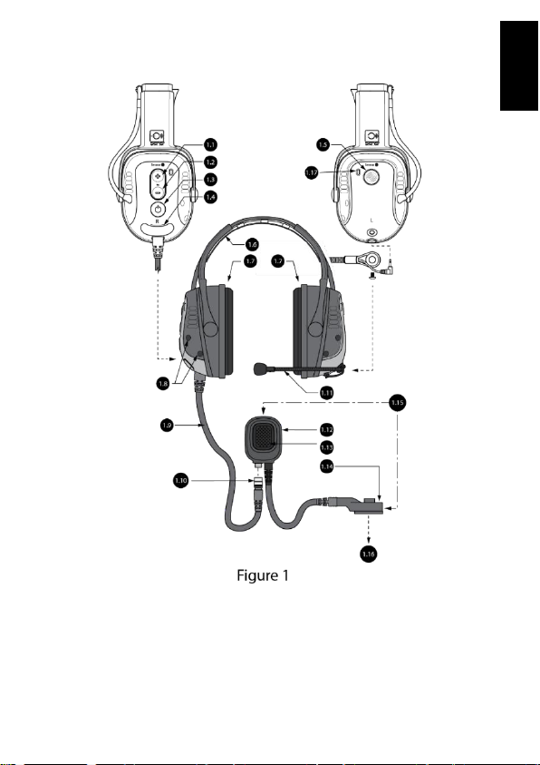
HEADSET ANATOMY
FIGURE 1

DOC00084 SM1P/B Manual rev 12.00
4
English
#
Description
1.1
Volume up button
1.2
Volume down button
1.3
Power button
1.4
Hatch cover, for programming and charging
1.5
Multi-function button (MFB)
1.6
Headband*
1.7
Ear cushions
1.8
Microphones
1.9
Headset cable
1.10
Headset connector
1.11
Boom microphone
Mount - M5 Hex screw
Connector - 2.5mm Audio jack
1.12
Inline PTT
1.13
Inline PTT button
1.14
Two-way radio connector (note, these will vary depending on your
two-way radio)
1.15
SRCK61XX cable assembly
1.16
To the two-way radio
1.17
LED light (one on each side of headset)

DOC00084 SM1P/B Manual rev 12.00
5
English
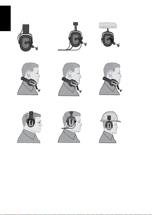
WEARING THE HEADSET
FIGURE 2
#
Description
2.1
Headset
2.2
Boom microphone
2.3
Inline PTT
2.4
Two-way radio

DOC00084 SM1P/B Manual rev 12.00
6
English
The SM1P B headset is designed to be worn with the headset sealing
around the ears. Specific examples of how to fit the headset around the
ears are covered in the next three pages. The fit does alter slightly
depending on what style of brace is used - headband, behind the neck or
mounted to a helmet directly.
The boom microphone should be placed approximately 5mm (1/4”) in
front of the mouth. Check to ensure the white dot or microphone label is
facing towards you. The orientation is essential as the microphone is
directional. If the microphone faces a different direction, this may lead to
a reduction in transmission quality.
The inline PTT has a rotatable clip behind it to allow it to attach to the
shirt / upper garment.
The inline PTT must be connected to the two-way radio using the multipin connector.
FITTING THE HEADSET
It is recommended that the wearer should ensure that;
• The ear muffs are fitted, adjusted and maintained in accordance
with the manufacturer’s instructions
• The ear muffs are worn at all times in high noise conditions
If the above recommendations are not adhered to, the protection
afforded by the ear muffs will be severely impaired.
DOC00084 SM1P/B Manual rev 12.00
7
English
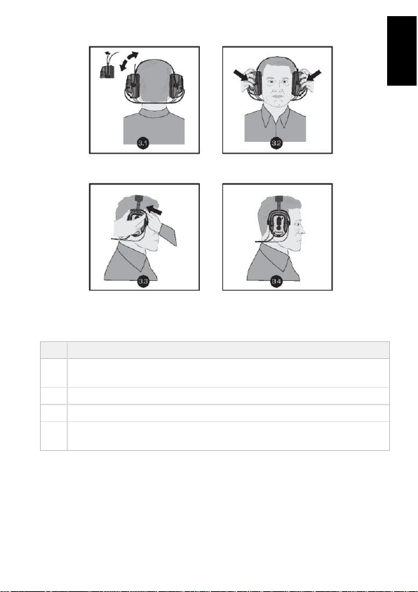
Behind the neck mount fitting instructions
#
Description
3.1
Adjust velcro strap so that the ear muff cups completely enclose
the ears.
3.2
The ear muff cushions should seal firmly against the head.
3.3
For best results, remove all hair from under the ear cushion.
3.4
Noise reduction will be adversely affected by anything that breaks
the seal of the ear muff ear cushions.

DOC00084 SM1P/B Manual rev 12.00
8
English
Headband mount fitting instructions
#
Description
4.1
Adjust the headband by pulling the centre band out equally on both
sides.
4.2
Ensure no hair is inside the muff ear cushions.
4.3
Fit the ear muffs over the ears ensuring a tight fit around the ears.
4.4
Ensure the muff completely surrounds the ears.
4.5
Press down on the headband to obtain a snug and comfortable fit.
DOC00084 SM1P/B Manual rev 12.00
9
English
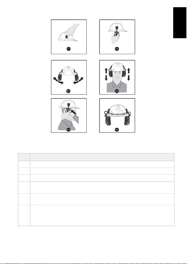
Helmet mount fitting instructions
#
Description
5.1
Attach the adaptors to each side of the helmet by sliding them into the slots.
5.2
Attach the earmuffs by sliding into the adaptors.
5.3
Ensure the earmuff is firmly attached by lifting the arm up and down.
5.4
Place the helmet on the head and adjust by sliding the ear muffs up and
down.
5.5
Earmuffs should seal firmly against the head. For best results, remove hair
from under the ear muffs.
5.6
Three adhesive mounts and ties are included to secure the ear muff cable to
the helmet. The mounts should be evenly spaced around the rear outside of
the helmet. Fit the tie through the mount. The cable should feed through
each tie and secured in place.
DOC00084 SM1P/B Manual rev 12.00
10
English
Dual protection fitting instructions
Locate the ear buds inside the ear cup.
Place earmuff away from the ears while fitting the ear buds. Insert ear
tips following the ear tip fitting instructions on next page.
Place the earmuff back over the ears. Ensure the retractable, coiled
cable is fully located within the ear cup. Noise reduction will be adversely
affected by anything that breaks the seal of the earmuff cushions.

DOC00084 SM1P/B Manual rev 12.00
11
English
Silicone ear tip fitting instructions
DO NOT roll the ear
tip between your
fingers as the tip
has been preshaped for easy
insertion
Place ear tip at an
angle to the plastic
canal
Push the ear tip
firmly over the
plastic canal
Foam ear tip fitting instructions
Ensure hands and
foam tip are clean
before insertion.
Place foam tip at an
angle to plastic
canal
Push the ear tip
firmly over the
plastic canal
Compress the foam
to form a cylindrical
shape being careful
not to crease the
foam

DOC00084 SM1P/B Manual rev 12.00
12
English
Gently pull your ear up and backwards with one hand while inserting the
ear plug into the ear. Foam ear tips should be inserted within 5 seconds
of compressing the foam. Make sure the plug seals well into the ear
canal. The ear tip should not protrude out of the ear canal. If using foam
ear tips hold the plug in place for 20 seconds or until the foam has fully
expanded.
OPERATING THE HEADSET
POWER ON:
1. Press and release the “Power” button shown in Figure 1.
2. All the LEDs will turn on briefly, & an audible sound will be heard
through the headset.
3. The Green LED will flash at a normal rate as described below.
POWER OFF:
1. Press and hold the “Power” button for 2 seconds.
2. All the LEDs will turn on briefly and an audible sound will be heard
through the headset as the headset powers off.
MODE:
When the headset is powered up, the unit is set into ‘ mode’**. By
pressing the power button, this toggles ‘ mode’.
‘ mode’ allows full situational awareness of your surroundings in
addition to two-way radio communications.
• The power button toggles between Quiet mode
and mode
 Loading...