

Page 1

The KFT-2410R supply was designed for industrial
installations where operation is continuous and requires
reliable components.
Built with the most modern techniques of switching with high
performance and small footprint supplys, and excellent
stabilization and regulation.
Supply Fixing:
Fixing the supply internally in the
panel must be made using 35mm
rails (DIN-46277).
Follow the procedures below:
1° Place only the supply upper
bracket on the rail . (Fig.03)
2 º Lower the supply until it fully
engages on the rail. (Fig. 04).
3º We recommend installing stops
so that the supply does not slide on
the rail. (Fig 05).
Horizontal mounting:
We recommend mounting in a
horizontal position in order to
ensure improved air circulation and
that the panel is provided with a ventilation system to prevent
overheating of the internal components.
Note: We recommend also leaving a gap of at least 20mm
from one supply to another, in order to improve the cooling.
Electric Installation:
The supply has 9 terminals according to the table below:
Terminal Description
1 and 2
Positive output 24 Vdc
3 and 4
Negative output 24Vdc
5 and 6 Alarm
7 and 9 AC input
8
Ground
Wire Preparation:
Do the ends of the wires according to the drawing below:
Be careful when removing the protective cover not to make
small cuts in the wires, as this may cause short circuit.
Note: The minimum wire size for an output current of 10A must
be 1mm2.
Procedures:
Remove the protective cover, insert the terminals and crimp
them. If you want to tin the ends for better grip.
Terminals:
To avoid problems of poor contacts and shorting advise using
pre-insulated terminals crimped on the wires.
AC input:
The KFT-2410R power supply has an automatic selection
circuit for 110 or 220Vac (full range), which prevents damage
to the supply with the improper selection / connection of the
equipment.
Voltage Power Current
110 Vac 187 VA 1,7 A
220 Vac 220 VA 1 A
Note: The values shown in the table above are for the condition
of maximum load (10A) in the supply.
AC Input Protection:
We recommend using the electrical circuit that supplies the
unit by a protection circuit breaker or fuse.
Supply Terminals:
• Loosen the terminal screw using a switch with a diameter of
3 to 3,5mm.
• Insert the wire with the terminal already applied, from the
bottom of the terminal.
• Tighten the terminal screw, and repeat for the other
terminals.
• Verify that actually wires are securely attached by pulling
them lightly.
Output Voltage:
The unit has a stabilized output voltage regardless of the
current drawn.
The direct current output, positive (1 or 2) and negative (3 or
4) terminals of the unit provides 24VDC with capacity for up to
10A.
We recommend its use for automation circuits supply such as:
electronic sensors
PLC input or output cards.
electronic modules
auxiliary relays
Current loops
• Industrial networks Profibus DP and DeviceNet standards
Signalling Led:
The supply has on its front a two-color LED whose function is
described in the table below:
Led Status Function
Green on Normal operation
Green off stand by
Red on Short-circuit or overload
Note: The standby condition (sleep) occurs when the supply is
working in parallel with each other and with lower output
voltage than other supplys, and this condition does not provide
(splits) current to the load.
Rua Tuiuti, 1237 - CEP: 03081-000 - São Paulo
Tel.: 11 2145-0444 - Fax.: 11 2145-0404
vendas@sense.com.br - www.sense.com.br
INSTRUCTIONS MANUAL
Switching Power Supply
KFT-2410R/110-220Vac
Tab. 8
Fig.7
1 2 3 4 5 6
7 8 9
Fig. 1
Pic. 2
Alicate ZA3Alicate ZA3
Pic. 10
Pic. 11
+ +
- -
55
FF
110 ou
220Vca
F F
N N
4040
55
Pic. 9
Fig. 3
Fig. 4
Fig. 6
FONTE DE ALIMENTAÇÃOFONTE DE ALIMENTAÇÃO
LEDLED
FF
FF
NN
CORRENTE ALTERNADACORRENTE ALTERNADA
110 ou 220Vca110 ou 220Vca
EMEM
ENTRADAENTRADA
CORRENTE CONTINUACORRENTE CONTINUA
SAÍDASAÍDA
--
++
24Vcc24Vcc
--
++
ALARMEALARME
Fig. 5
EA3000830- Rev. Bi - 09/15
21 .baT
Pic. 13
Fig. 14
Fig. 15
Fig. 16
Tab. 17
Page 2
Output Ripple:
It is possible that a small ripple and a small output noise is
noticed and may even audio noise characteristic occur, do not
represent a malfunction to the supply.
Protection Against Short-Circuit:
The protection circuit is the oscillating type of automatic
recovery, ie, when the protection operates the output
de-energizes itself, and the supply back to operate
automatically once the overload is removed.
The short protection circuit acts as a power limiter, where the
output voltage is reduced due to the overload current, as
shown in the chart below:
Restoring After Overload:
If the supply is not supplying energy without , overload, must
proceed:
Remove the overload or decrease font loads.
Disconnect and reconnect the AC power supply.
• If power not restored withdraw all charges deenergizing the
24 Vdc output and reconnect the AC input.
Output Voltage Adjustment:
If the supply is far from its loading center , the output voltage
can be raised slightly by correcting the excessive voltage drop
that may exist at the end of the line. To do so you must check
the maximum allowable voltage for all devices connected to
the line.
The tension adjustment is made via a one pot back on the front
of the fountain below the LED status. The potentiometer allows
you to adjust the output voltage of 22V to 28V. Turn the trimpot
counter-clockwise to decrease tension and counterclockwise
to increase it.
Minimum Load:
So that the supply function properly, it is needed a minimum
load of 1A, otherwise there will be a little instability in the supply
due to narrowing of the PWM pulse, which DOES NOT cause
problems, so it is possible that the supply function without
charge, without risk to the user, but its output voltage
regulation and can not be within the values established by
having the supply indicates a nonexistent failure.
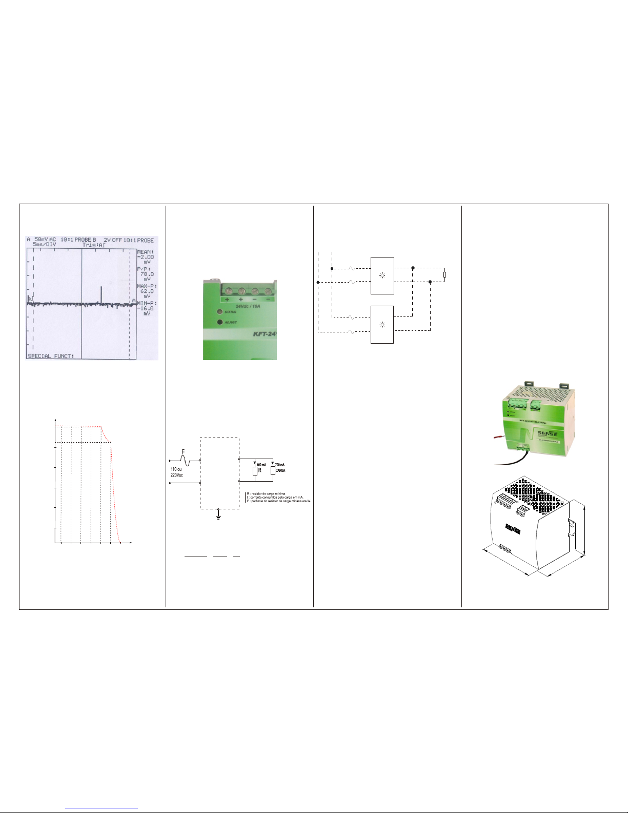
Minimum Load Resistor:
In the figure below minimum load resistor is installed in parallel
with the load so that the total supply current is not less than 1A.
Resistor Calculation:
The load resistor should be calculated with the addition of
current drawn by the load current for minimum, as:
R
Ic a=-
=-= =
24124
1 072403
80
arg , ,
W
P Ic a x W= - = - = =24 1 24 1 07 24 03 7 2. ( arg ) . ( , ) , ,
For I load < 1A.
Redundance:
The supply is redundant type. Two or more supplies may be
connected in parallel. Thus, even if a defect in one supply, the
power supply will not be interrupted.
Alarm:
• The supply has an alarm relay, which is especially suitable
for applications where dual power supplies, to indicate that
one supply is not operating. The contact used to indicate
remotely that one supply stops working.
Conditions that make the alarm contact open:
Lack of AC current at the input.
• defect in the internal circuitry of the energy transformation.
Note: when the supply is in stand-by contact remains closed.
Load Division:
In applications with redundant power supplies, we recommend
that supplies divide the load current, so that if one fails the
other only increase the current supplied without prejudice to
the load.
The division need not be equally distributed by supplies
recommend only adjust the output voltage so that the green
LED output lights up, indicating that the supply is supplying
current.
For the current division is accurate, it is necessary to very
precisely adjust the output voltage to the same voltage supply,
but still can occur due to differences in wiring impedance.
Adjustment Procedure for Redundance:
• Taking as an example the design 22, disconnect the
positive output of each source.
Place a voltmeter accurate to 2 decimal places in the output of
the power and turn the potentiometer clockwise to increase
pressure or counterclockwise to decrease.
• Look adjust the two supplies with the same output voltage.
Adjustment Procedure for Isolated Supplies:
In the case of single supplies acting on the pot by raising or
lowering the output voltage by monitoring the voltage that
effectively reaches the load, compensating for voltage losses
in the cabling.
Incorrect Installation:
Attention! The improper installation or use can influence the
supply functioning, or even permanently damage the unit.
Safety Warnings:
Before working with the supply carefully read the instructions:
Before placing the supply in operation must be ensured:
• The connection of supply and output are consistent with the
connection diagram.
• Wires are securely attached to the terminals.
• That the cables are connected to the output load with
correct polarity.
• That the load does not exceed 10A.
• You have enough for the perfect functioning of the cooling
supply.
• Note that the wires have proper gauge for the current
transmitted.
Attention!
Never open the power while in operation, because the unit
contains components that store energy. Improper handling of
these can cause serious injury to the operator.
Caution!
Even after de-energized, the supply accumulates electricity.
Therefore we do not recommend open supply because very
strong electric shocks to risk death can occur in the handling.
KFT-2410R Care:
Be careful when connecting the terminals as contact wires with
metal housing may cause electric shock-threatening.
Mechanical Dimensions:
Fig. 18
24
20
16
12
8
4
0
2 4 6 8 10 10,5 11
V
A
21
Pic. 19
Vca
Fonte 1
Fonte 2
Vcc
F 1
F 2
CARGA
+
-
+
-
Pic. 22
Fig. 20
Pic. 21
Pic. 24
1
2
8
1
30
10
6
S
e
n
s
o
r
e
s
e
I
n
s
t
r
u
m
e
n
t
o
s
EA3000830- Rev. Bi - 09/15
Fig. 23
 Loading...