

Page 1

| DRMS SERIES
DIN RAIL MOUNT HYBRID MOTOR STARTERS
DRMS Series Hybrid Motor Starters are intelligent and convenient solutions for controlling 3-phase asynchronous motors. These compact devices can provide up
to 6 functions in the same unit: Forward/Reverse, Soft Start/Soft Stop, Motor Overload Protection, and Mains Isolating Relay.
Motor overload detection is based on a thermal load curve. The relays are de-energized when an overload condition is present, ensuring a long service life.
Features
• 3-phase motors reversing up to 4 kW
• 2-phase soft start/stop
• Up to 4 dials for setting of starting torque, deceleration torque, soft start/
stop, and rated motor current
• 4 LEDs for status indication
• Galvanic separated 24 VDC inputs for forward and reverse control
• Reset button on front, with connection for external reset
• Relay indicator output for operation
• Hybrid relay combines benefits of electromechanical relay technology with
non-wearing semiconductor technology
• High reliability by temperature monitoring of semiconductors
Applications
• Reversing operation for door and gate controls, bridge drives and lifting
applications with monitoring of blockage
• Conveyor systems with monitoring of blockage
• Actuating drives in process controls with blockage monitoring
PRODUCT SELECTION
Part Number Functions
DRMS48D91
DRMS48D92
DRMS48D93
Forward/Reverse, Overload Protection
Forward/Reverse, Overload Protection, Soft Start/Stop
Forward/Reverse, Overload Protection, Soft Start/Stop, Mains Isolating Relay
SPECIFICATIONS
Output
Description DRMS48D9x
Operating Voltage L1/L2/L3 [Vrms]
Nominal Frequency [Hz]
Peak Reverse Voltage [Vpk]
Overvoltage Limiting [Vrms]
(1)
200-480 ± 10%
50/60, automatic detection
1500
550
Page 1
Page 2

Maximum Off-State Leakage Current @
Rated Voltage [mArms]
Load Current, AC51 [Arms]
(2)
Load Current, AC53a: 6-2: 10-30 IEC/EN
60947-4-2 [Arms]
(2)
Maximum Motor Power [kW] @ 400 VAC
Minimum Motor Power [W]
Maximum Surge Current [Apk] t = 20 msec
Load Limit Integral [A²sec] t = 10 msec
Starting Voltage
Start / deceleration ramp [sec]
Switchover Delay Time [msec]
Max. Fuse Rating per IEC/EN 60947-5-1
Electrical Life
0.5
9
7.6
4
25
200
200
30-80%
1-10
250
25 A gG / gL
> 107 cycles
Motor Protection
(1)
Description DRMS48D9x
Ie: 1.5 A to 6.8 A
Ie: 6.9 A to 9.0 A
Protection type
Reset
(1)
Input
Class 10 / 10 A
Class 5
Electronic, without thermal memory
Manual
Description DRMS48D9x
Control Voltage Range (R, L)
Minimum Turn-On Voltage
Must Turn-Off Voltage
Typical Input Current
Polarity Reversal Protected
Manual Reset Voltage Range
Auxiliary Power Supply
(1) (3)
10-30 VDC
10 VDC
8 VDC
4 mA
Yes
10-30 VDC
Description DRMS48D9x
Voltage Range
Power Consumption
Min. Start Up Delay
Min. Release Delay
24 VDC ±10%
2 W
100 msec
50 msec
Page 2
Page 3

Indicator Outputs
(1)
Description DRMS48D9x
Output Type (Ready)
Switching Capacity to AC 15 per IEC/EN
1 Changeover Contact (SPDT)
3 A / 230 VAC
60947-5-1, NO Contact
Switching Capacity to AC 15 per IEC/EN
1 A / 230 VAC
60947-5-1, NC Contact
Thermal Current, Ith
Electrical Life to AC15 @ 3A, 230 VAC per
5 A
2 x 10⁵ Cycles
IEC/EN 60947-5-1
Mechanical Life
Maximum Switching Frequency
Max. Fuse Rating per IEC/EN 60947-5-1
30 x 106 Cycles
1800 cycles/hr
4 A gG / gL
General
(1)
Description DRMS48D9x
Device Type
Rated Insulation Voltage
Overvoltage Category / Contamination
Hybrid Motor Controller
500 V
4 kV / 2
Level per IEC/EN 60664-1
Ambient Operating Temperature Range
Ambient Storage Temperature Range
Weight (Typical)
Housing Color
LED Status Indicators
Protection Degree, Housing
Protection Degree, Terminals
Humidity @ 40 °C
Control Terminal Screw Torque (lb-in/Nm)
Load Terminal Screw Torque (lb-in/Nm)
Control Terminal Wire Capacity
Load Terminal Wire Capacity
0 to 60 °C
-25 to 75 °C
188 g
Black and Light Gray
See Indicators Chart
IP40
IP20
93% non condensing
3.46 / 0.39
5-7 / 0.56-0.79
1 x 22-14 AWG (IEC 0.5-2.5 mm²) (stranded/solid)
1 x 30-12 AWG (IEC 0.05-4 mm²) (stranded/solid)
GENERAL NOTES
(1)
All parameters at 25°C unless otherwise specified.
(2)
To achieve maximum ratings there must be a minimum spacing of 0.9 in (22mm) between the devices in free air (see derating curves).
(3)
For reliable operation the 24 VDC auxiliary power supply needs to be fully stable during the entire operation of the device. Removing this volt-
age while the output is under load could cause permanent damage to the device.
Additional Notes
• This device is intended for use on supply systems with a maximum voltage from phase to ground of 300 V (e.g. for a three phase-four wire system
277/480 V or on a three phase-three wire systems of 240 V), rated impulse withstand voltage of max. 4 kV.
• Suitable for use on a circuit capable of delivering not more than 5000 rms symmetrical Amperes, 480 Volts maximum when protected by class CC,
J or RK5 fuse rated maximum 20 A.
• For use in pollution degree 2 Environment or equivalent.
• The control circuits of this device shall be supplied by an isolated 24 VDC power supply which output is protected with a fuse rated max. 4 Adc.
Page 3
Page 4
• For installations according to Canadian National Standard C22.2 No. 14-13 (cUL Mark only) and supply voltages above 400V:
• For 415 V max. supply voltage, transient surge suppression devices shall be installed on the line side of this equipment and shall be rated 240
V (phase to ground), 415 V (phase to phase), suitable for overvoltage category III, and shall provide protection for a rated impulse withstand
voltage peak of 4 kV.
• For 480 V max. supply voltage, transient surge suppression devices shall be installed on the line side of this equipment and shall be rated 277
V (phase to ground), 480 V (phase to phase), suitable for overvoltage category III, and shall provide protection for a rated impulse withstand
voltage peak of 4 kV.
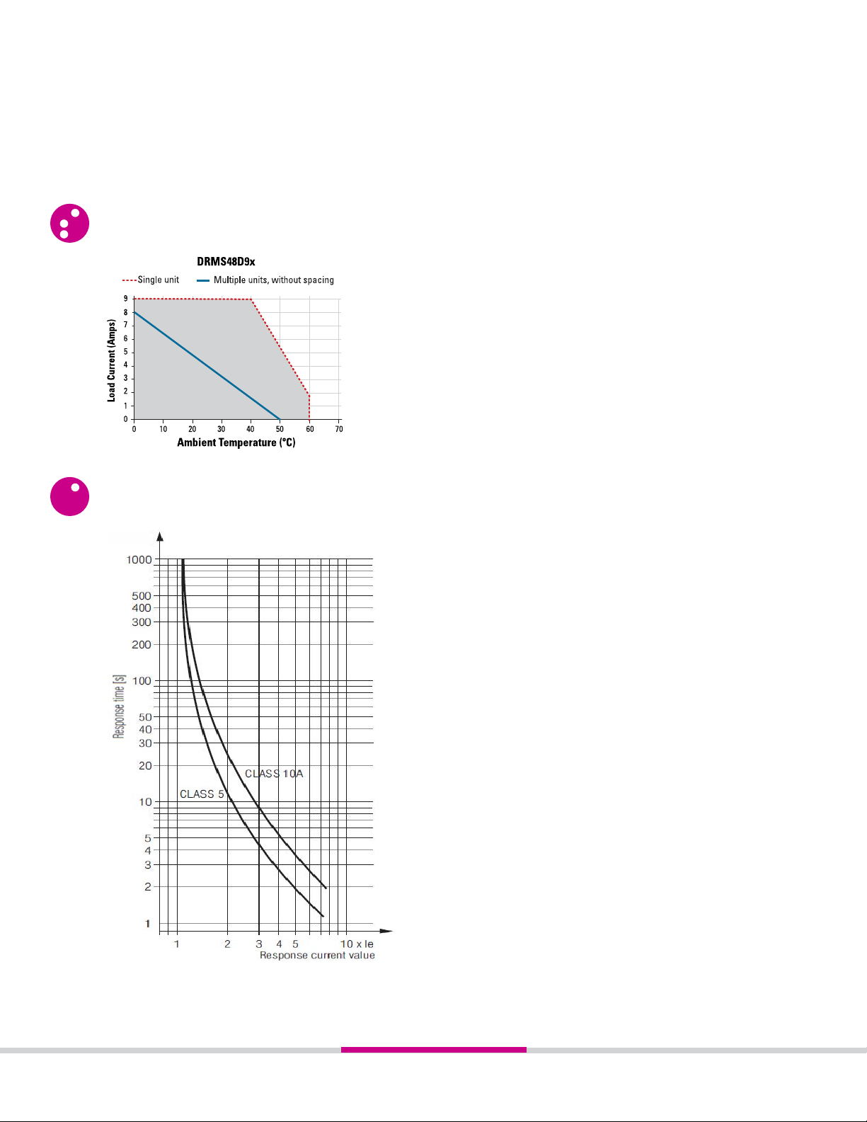
THERMAL DERATE INFORMATION
MOTOR OVERLOAD PROTECTION CURVES
Page 4
Page 5

EQUIVALENT CIRCUIT BLOCK AND WIRING DIAGRAMS
TABLE 3. Connection Terminals
Terminal Designator Description
V+
0V
R
L
NE
Auxiliary voltage +
Auxiliary voltage Control input Forward
Control input Reverse
Earth connection control input
MAN
RES
11, 12, 14
L1
L2
L3
T1
T2
T3
Input for remote Reset
Output for remote Reset
Indicator relay for operation
Phase voltage L1
Phase voltage L2
Phase voltage L3
Motor connection T1
Motor connection T2
Motor connection T3
(3) (3)
Page 5
Page 6

INSTALLATION INSTRUCTIONS
• Install the motor starter on the DIN rail, as shown on fig. 1.
• Wire the motor starter to the control side. AWG #22 (0.5mm²) minimum, AWG
#14 (2.5mm²) maximum.
• Wire the motor starter to the output side. AWG #30 (0.05mm²) minimum, AWG
#12 (4 mm²) maximum (stranded/solid).
• Maximum terminal screw torque control side 3.46 lb-in (0.39 Nm) & output side
5-7 lb-in (0.564-0.79 Nm).
• Use 60°C / 75°C copper conductors only.
• If multiple units are installed, be sure to follow derating curves.
When designing circuits with this motor starter unit, components
that generate magnetic fields like contactors, transformers, or high
WARNING! Latching system could be damaged if
product is removed incorrectly out of the DIN rail.
current wires, should not be placed close to the current sensor.
Safety Notes:
- Never clear a fault when the device is switched on.
- The user must ensure that the device and the necessary component are mounted and connected according to the locally applicable regulations and
technical standards (UL, VDE, TÜV, BG).
- Adjustments may only be carried out by qualified specialist staff and the applicable safety rules must be observed.
- After a short circuit the motor starter is damaged and has to be replaced (Assignment type 1).
- If several motor starter devices are protected together, the sum of the motor currents must not exceed 25 A.
SETUP PROCEDURE
1. Wire the motor and the motor starter device according to the wiring diagrams examples. A forward (clockwise) rotating field is
assumed for normal operation. A anti-clockwise rotating field triggers a fault message.
2. Turn TON/TOFF dial fully clockwise, MON and MOFF dials fully anti-clockwise, and Ie dial to the required current.
3. Connect voltage and start the motor using control inputs R and L.
4. The starting time is set by turning the TON dial anti-clockwise and the starting torque is set by turning the MON dial clockwise to the
desired value. If set correctly, the motor shall swiftly accelerate to the nominal speed.
Indicator
PWR Green Permanent ON
LED
Color
Status Description
Auxiliary supply connected.
R Yellow
L Yellow
ERR Red
Permanent ON
Flashing
Permanent ON
Flashing
Flashing
1 pulse
2 pulses
3 pulses
4 pulses
5 pulses
6 pulses
7 pulses
8 pulses
Forward, power semiconductors bridged.
Forward, ramp operation.
Reverse, power semiconductors bridged.
Reverse, ramp operation.
Error detected:
Over temperature on semiconductors.
Wrong mains frecuency.
Phase reversal detected.
At least 1 phase is missing.
Motor overcurrent detected.
Mains isolating relay not disconnected.
Incorrect mesurement circuit.
Motor protection has responded.
Page 6
Page 7

FUNCTION DIAGRAMS
tu = switchover delay time
tp = overload response time according to characteristic
class 10A or 5
DEVICE OPERATION
Forward/Reverse Control
Forward (clockwise) and reverse (anticlockwise) rotation can be selected via control inputs R and L respectively. The input signal detected first is executed if both inputs are applied simultaneously. After the detected signal is cancelled, the rotational direction is reversed via the Soft Start function.
These control inputs have a common isolated ground connection NE.
Soft Start
Two motor phases are switched using phase-angle control to allow a steady increase of the phase currents. The motor torque increases in the same
manner when ramping up. This operation ensures the motor starts smoothly and helps to extend the life of the motor and the motor starter. The ramp
up time TON and starting torque MON can be adjusted via a rotary dial at the front.
Soft Stop
The Soft Stop function extends the natural run down time of the motor starter to allow for a smooth stop. The ramp down time TOFF, which is equal
to the ramp up time, and the decelaration torque MOFF can be adjusted via a rotary dial at the front.
Page 7
Page 8

Motor Overload Protection
The thermal load of the motor is calculated using a thermal model (see Thermal Overload Protection Curves). The nominal motor current Ie can be
adjusted via a potentiometer on the front. To calculate the thermal load the current is measured in phase T3.
A symmetrical load current in all 3 phases of the motor is assumed for flawless operation. When the trigger value, stored in the trigger characteristics, is reached, the motor is switched off and the device switches to fault 8. The fault can be acknowledged via the front Reset button or via the
external Reset input.
IMPORTANT: The data of the thermal model can be cleared through a Reset or by removing power to the unit. In this case, the user must provide
adequate cooling time to the motor.
Phase Failure Detection
To make sure the motor is not asymmetrically loaded a check takes place during the motor start to determine if phases L1, L2 and L3 are present. If
one or several phases are absent then the device switches to fault 4. The fault can be acknowledged via the Reset button or via the external Reset
input.
Mains Isolating Relay (only for model DRMS48D93)
In the off state or when a fault condition is detected the motor terminals are isolated from the mains voltage by a 4-pole forcibly guided contact
relay. The contact opening is min. 0.5 mm.
IMPORTANT: Do not remove the 24 VDC auxiliary supply voltage while the output is under load. Failure to do so can cause a permanent damage to
the mains isolating Relay.
Signalling Output Relay
Contact 11/14 is closed if no fault is present on the device.
Reset Function
There are 2 options available to acknowledge a fault condition:
Front Reset button:
Acknowledgement is done by momentarily pressing the Reset button at the front of the device. If the button is still pressed after 2 seconds the
device resumes the fault state.
Remote Reset input:
Remote acknowledgement can be accomplished by connecting an external switch (Normally Open) between terminals MAN and RES. Acknowledgement is triggered as soon as this external contact closes. If the contact is still actuated after 2 seconds the device resumes the fault state since a
defect in the acknowledgement circuit cannot be ruled out.
DIMENSIONS
± 0.02 in / 0.5 mm.
All dimensions are in: in [mm]
DRMS48D91
INPUT TERMINAL SLOT
SCREW (12 PLACES)
OUTPUT TERMINAL SLOT
SCREW (6 PLACES)
Page 8
Page 9

4 74
120.3
DRMS48D92, DRMS48D93
4 54
115.3
4.29
109
4 21
107
.03
00
+0 7
0
69
17.5
4.74
120.3
4.54
+.03
115 3
4.29
109
4.21
107
00
+0.7
0
.69
17.5
Page 9
Page 10

ORDERING OPTIONS
Example : DRMS48D91
DRMS
48 D 9 1
Series
DRMS
Operating Voltage
48: 200-4 80 VAC
Control Voltage
D: 10-30 VDC
Load Current per Phase
9: 9 Amps
Function
1: Reversing Contactor with Overload Protection
2: Reversing Contactor with Soft Start, Sof t Stop and Overload Protection
3: Reversing Contactor with Soft Start, Soft Stop, Overload Protection and Mains Isolating Relay
AGENCY APPROVALS & CERTIFICATIONS
Tested and Certified According To
E116949
UL 508 and C22.2 No.14-13
With restrictions at motor switching power:
- ANSI/UL 60947-1, 3rd Edition (Low-Voltage Switchgear and Controlgear Part1: General rules)
- ANSI/UL 60947-4-2, 1st Edition (Low-Voltage Switchgear and Controlgear Part 4-2: Contactors and Motor-Starters - AC Semiconductor Motor
Controllers and Starters)
- CAN/CSA-C22.2 No. 60947-1-07, 1st Edition (Low-Voltage Switchgear and Controlgear - Part1: General rules)
- CSA-C22.2 No. 60947-4-2-14, 1st Edition (Low-Voltage Switchgear and Controlgear - Part 4-2: Contactors and Motor-Starters - AC Semiconductor
Motor Controllers and Starters
DRMS Motor Circuit Ratings
Per UL508, CSA C22.2 No. 14-13
Network Voltage Ambient Temperature FLA / LRA
40ºC 7.6 / 45.6
200-480VAC, 3-phase, 50/60Hz
50ºC 4.8 / 28.8
60ºC 2.1 / 12.6
Per UL 60947-4-2, CSA 60947-4-2
40ºC 7.6 / 45.6
200-300VAC, 3-phase, 50/60Hz
301-480VAC, 3-phase, 50/60Hz 60ºC 2.1 / 12.6
50ºC 4.8 / 28.8
60ºC 2.1 / 12.6
Page 10
Page 11

CONFORMANCE ENVIRONMENTAL
Directive 2006/95/EC Directive 2011/65/EU
IEC/EN 60068-2-6: Vibration Resistance - Amplitude 0.35mm, frequency 10-55 Hz
IEC/EN 60068-1: Climate Resistance - 0 / 060 / 04
ELECTROMAGNETIC COMPATIBILITY
Interference resistance
IEC/EN 61000-4-2: Electrostatic Discharge - 8 kV (air)
IEC/EN 61000-4-3: HF-Irradiation - 80 MHz-1.0 GHz: 10 V/m
1.0-2.5 GHz: 3 V/m
2.5-2.7 GHz: 1 V/m
IEC/EN 61000-4-4: Fast Transients - 2 kV
IEC/EN 61000-4-5: Surge Voltage between Wires for Power Supply - 1 kV
Surge Voltage between Wires and Ground - 2 kV
IEC/EN 61000-4-6: HF-Wire Guided - 10 V
IEC/EN 61000-4-11: Voltage Dips
Interference emission
IEC/EN 60947-4-2: Wire guided - Limit value class B
Radio irradiation - Limit value class B
WARNINGS
RISK OF MATERIAL DAMAGE AND HOT ENCLOSURE
• The product’s side panels may be hot, allow the product to cool before touching
• Follow proper mounting instructions including torque values
• Do not allow liquids or foreign objects to enter this product
Failure to follow these instructions can result in serious injury, or equipment damage.
HAZARD OF ELECTRIC SHOCK, EXPLOSION OR ARC FLASH
• Disconnect all power before installing or working with this equipment
• Verify all connections and replace all covers before turning on power
Failure to follow these instructions will result in death or serious injury.
Page 11
 Loading...