

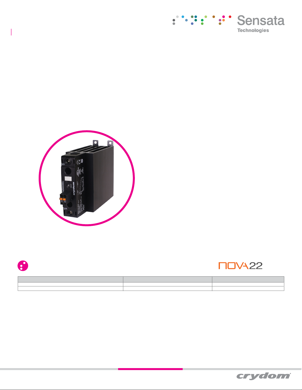
| DR45 SERIES
AC SINGLE PHASE OUTPUT DIN RAIL MOUNT SSRS
Introduction
The DR45 is a powerful and compact solid state relay in a DIN rail 45mm wide package with an output rating up to 60 Amps
@ 40°C offering mounting flexibility (on panel or DIN rail) and convenient input connection options. Its high I²t capability
and optional built-in overvoltage protection make it suitable for demanding heating, motion and lighting applications.
Its contactor configuration and large cage clamp terminals allow connecting wires up to 3 AWG size on the output without
the use of any additional accessories making them truly ready-to-use devices, therefore reducing installation cost and
time.
UL Listed and VDE certified, the DR45 is a safe and versatile solid state relay with superior performance when compared to
previous generation and competitor products in similar sized packages.
Features
• Output ratings up to 60 Amps at 600 VAC
• Built-in overvoltage protection
• Integral heat sink eliminates the need for complex
thermal calculations
• Cage clamp terminal type accept up to 3 AWG wire size
• IP20 touch-safe housing
• Contactor configuration
• AC or DC control
• C-UL-US Listed and VDE approved
Applications
• Plastic injection molding equipment
• Packaging equipment
• Industrial ovens
• Lighting control
• Pump control
• Conveyor drives
• HVAC&R
• Railway vehicles
PRODUCT SELECTION
Control Voltage 45A
90-280 VAC/VDC DR4560A45x
4-32 VDC
60A
DR4560A60x
DR4560D60xDR4560D45x
Copyright © 2017 Sensata Technologies Inc.
Page 1
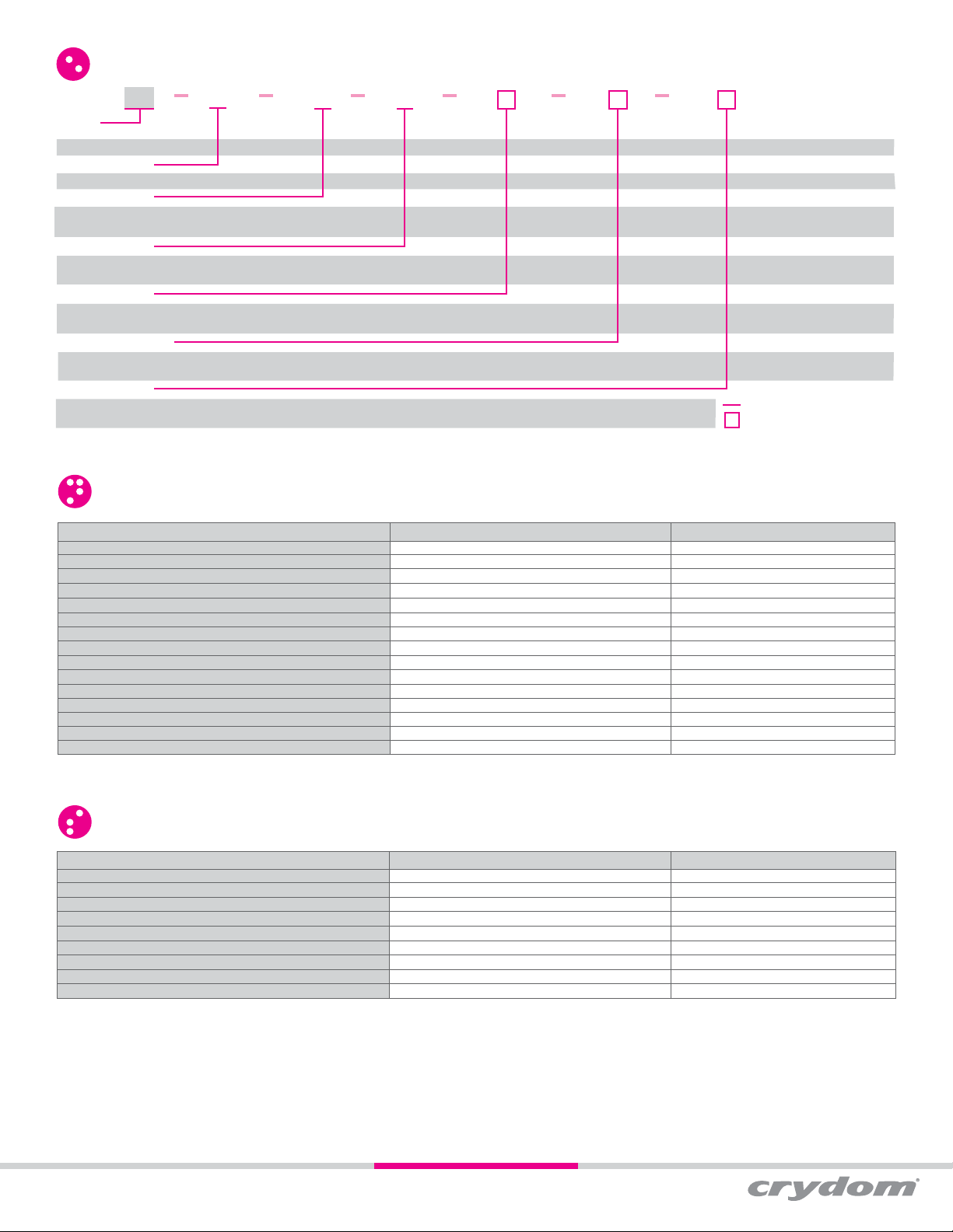
ORDERING OPTIONS
DR45
60 A 45 R JP
Series
DR45
Operating Voltage
60: 48-600 VAC
Control Voltage (1)
A: 90-280 VAC/VDC
D: 4-32 VDC
Rated Load Current
45: 45 Amps
60: 60 Amps
Switching Type
Blank: Zero Voltage Turn-On
R: Instantaneous Turn-On (Motor Rating Certified)
Overvoltage Protection
Blank: Not Included
P: Included
Input Connector
Blank: Screw Terminal
J: Spring Terminal
OUTPUT SPECIFICATIONS
(2)
Description 45A
Operating Voltage (45-65Hz) [VRMS] 48-600
Transient Overvoltage [Vpk]
Maximum Off-State Leakage Current @ Rated Voltage [mA
Minimum Off-State dV/dt @ Maximum Rated Voltage [V/μsec] 500
Load Current, General Use UL508/LC A IEC62314 @ 40°C [A
Load Current, Motor Starting UL508 FLA/LC B IEC62314 @ 40°C [ARMS] 14/7.6
Minimum Load Current [mA
Maximum 1 Cycle Surge Current (50/60Hz) [Apk] 716/750
Maximum On-State Voltage Drop @ Rated Current [V
Maximum 1/2 Cycle I² t for Fusing (50/60Hz) [A² sec] 2563/2343
Maximum Power Dissipation @ Rated Current [W] 52
Minimum Power Factor (at Maximum Load)
Motor Rating UL 508/IEC62314 [HP (kW)]: 120 VAC 1 (0.74)
Motor Rating UL 508/IEC62314 [HP (kW)]: 240 VAC 3 (2.2)
Motor Rating UL 508/IEC62314 [HP (kW)]: 480 VAC 5 (3.7)
(3) 1200
RMS] 1
RMS] 45
RMS] 100
RMS] 1.25
(4) 0.5
Required for valid part number
For options only and not
required for valid part number
60A
48-600
1200
1
500
60
26/14
150
1290/1350
1.15
8320/7593
69
0.5
2 (1.5)
5 (3.73)
10 (7.4)
INPUT SPECIFICATIONS
Description DR4560Axxx
Control Voltage Range 90-280 VAC/VDC
Maximum Reverse Voltage Minimum Turn-On Voltage 90 VAC/VDC
Must Turn-Off Voltage 5 VAC/VDC
Minimum Input Current (for on-state) 3 mA
Maximum Input Current 4 mA
Nominal Input Impedance Switch Mode
Maximum Turn-On Time [msec] 20
Maximum Turn-Off Time [msec] 30
(2)
DR4560Dxxx
4-32 VDC
(5)
-32 VDC
4 VDC
1 VDC
10 mA
15 mA
Current Limited
1/2 Cycle
1/2 Cycle
(6)
Copyright © 2017 Sensata Technologies Inc.
Page 2

GENERAL SPECIFICATIONS
(2)
Dielectric Strength, Input to Output (50/60Hz) 4000 V
Dielectric Strength, Input/Output to Case (50/60Hz)
Minimum Insulation Resistance (@ 500 VDC)
Maximum Capacitance, Input/Output 8 pF
Ambient Operating Temperature Range -40 to 80 °C
Ambient Storage Temperature Range
Short Circuit Current Rating
(7)
(8)
Weight (typical) 17.63 oz (500 g)
Housing Material UL94 V-0
Heat Sink Material Aluminum
DIN Rail Clip Material Zinc Plated Steel
Hardware Finish Nickel Plating
Input Terminal Screw Torque Range (lb-in/Nm) 5/0.5
Load Terminal Screw Torque Range (lb-in/Nm) 18-20/2-2.2
Humidity per IEC 60068-2-78 93% non-condensing
LED Input Status Indicator Green
Overvoltage Category III
Impulse Withstand Voltage According to IEC 60664-1 6kV
RMS
4000 V
RMS
109 Ohms
-40 to 100 °C
100kA
INPUT CURRENT INFORMATION
4-32 VDC Input
14
12
10
8
6
4
Input Current (mA)
2
0
ParametersDescription
0 5 10 15 20 25 30 35
Input Voltage (VDC)
SURGE CURRENT INFORMATION
DR4560x45x
700
600
500
400
300
200
100
Surge Current (Amp) AC Peak
0
0.01 0.1 1 10
THERMAL DERATE INFORMATION
DR4560x45x
60
50
40
30
20
10
Load Current (Amps)
Single unit
0
20 30 40 50 60 70 80
Ambient Temperature (ºC)
Surge Duration (sec)
(10)
Multiple units, no spacing
Single Pulse (9)
1400
1200
1000
800
600
400
200
Surge Current (Amp) AC Peak
0
0.01 0.1 1 10
DR4560x60x
80
70
60
50
40
30
20
Load Current (Amps)
10
Single unit
0
20 30 40 50 60 70 80
Ambient Temperature (ºC)
Multiple units, no spacing
DR4560x60x
Surge Duration (sec)
Page 3
Copyright © 2017 Sensata Technologies Inc.

EQUIVALENT CIRCUIT BLOCK DIAGRAMS/WIRING DIAGRAMS
* TVS option available in “P” version
+3/A1
INPUT
-4/A2
Current
Limiter
* TVS option available in “P” version
+3/A1
AC/DC
Converter
INPUT
-4/A2
Current
Limiter
Trigger
Circuit
Trigger
Circuit
AC/DC
DC Control
+
V
DC
-
AC/DC Control
+/
V
-/
INSTALLATION INSTRUCTIONS
Mounting on DIN Rail
• Locate rail and align with non moveable end of DR45 DIN clip.
• Using reasonable force, push DR45 in the direction of the arrow (as shown in fig.1).
• For removal pull release tag in direction of arrow using blade of screwdriver and
pull it away from DIN rail.
Mounting on Panel
• Locate the panel section on which the DR45 SSR will be mounted on (as shown in
fig.2)
• DIN clip includes tabs for this type of mounting. Tab holes have a diameter of 4.5 mm.
You will need three screws (not included) no larger than that to mount the SSR onto
panel.
• Align SSR tabs with panel surface and screw both top and bottom sides.
Recommended torque is 12 in-lbs (1.36 Nm).
Wiring Instructions
• Recommended wire sizes as shown in TABLE 1
• Maximum terminal screw torque input terminal 5 lb-in (0.5 Nm) (screw terminal only)
• Maximum terminal screw torque load terminal 18-20 lb-in (2.0-2.2 Nm)
• If multiple units are installed be sure to follow derating curves
Load
1/L1
*
2/T1
Load can be wired in position A or B
1/L1
*
2/T1
Load can be wired in position A or B
OUTPUT
OUTPUT
Load
Load
Load
A
AC
V
B
A
ACV
B
TABLE 1. Wire Size & Pull Out Strenght
Terminal
Configuration
Output
Screw
Input
Spring
* Tests performed on Stranded wire
WARNING! Removing product from 35 mm rail incorrectly by not using the
appropriate tool would damage the latching system.
Recommended Wire Size
(Solid / Stranded)
2
1 x 18 AWG (1 mm
) [minimum]
1 x 8 AWG (10 mm2) [maximum]
2 x 8 AWG (10 mm2) [maximum]
1 x 3 AWG (26.67 mm2) [maximum]
30 AWG (0.05 mm2) [minimum]
12 AWG (3.3 mm2) [maximum]
26 AWG (0.13 mm2) [minimum]
12 AWG (3.3 mm2) [maximum]
Wire Pull-Out
Strength (lb)[N]
20 [88]
90 [400]
80 [355]
90 [400]
4.5 [20]
30 [133]
5 [22]
5 [22]
*
To install
on DIN rail
To remove
from DIN rail
fig. 1 SSR mounted on DIN rail
Copyright © 2017 Sensata Technologies Inc.
DIN rail
(35mm)
fig. 2 SSR mounted on Panel Mount
Page 4

MECHANICAL SPECIFICATIONS
Tolerances: ±0.02 in / 0.5 mm
All dimensions are in: inches [millimeters]
1.43
[36.4]
1.88
2.94
[47.8]
[74.8]
ACCESSORIES
Recommended Accessories
Connectors
CP201
Screw Terminal
CP202
Spring Terminal
ID Marker
Blank Strips
Numbered 1 to 10 Strips
Numbered 11 to 20 Strips
1.77
[45]
CNLB
CNLN
CNL2
0.91
[23.1]
3.62
[92]
4.39
[111.5]
5.36
[136]
6.08
[154.4]
Protective Earth Connection
Protective earth (PE) screw type recommended
is 10-32 UNC standard not provided with SSR.
Through the use of a DIN rail ground (protective
conductor) terminal block, the DIN rail itself
can be used as the grounding bus bar. In this
case, the zinc plated steel material used for the
DIN rail clip of DR45 models, permits a secure
path to ground and avoid the need of a further
PE connection.
10-32
Thread
Copyright © 2017 Sensata Technologies Inc.
Page 5

AGENCY APPROVALS, CONFORMANCES, ENVIRONMENTAL AND EMC
Copyright © 2017 Sensata Technologies Inc.
Approvals (Tested and Certified according To)
E116949
UL 508 and C22.2 No. 14
Vibration and Shock
Resistance
IEC 61373: Category 1,
Class B
Generic
Standard
Electrostatic Discharge
IEC 61000-4-2
Fast transients (burst)
IEC 61000-6-2
Immunity for
IEC 61000-4-4
Industrial
Environments
Surge
IEC 61000-4-5
REG-Nr. xxxxxx
EN 62314
Conformances Environmental
Designed in
accordance with
Resistances to heat
and fire
IEC 60950-1 IEC 60335-1, Section 30 Directive 2006/95/EC Directive 2011/65/EU GBT 26572-2011
Electromagnetic Compatibility
Immunity Tests Test Specification Level
8kV air discharge
6kV contact discharge
Output 2kV, 5kHz, 100kHz
Input 1kV, 5kHz, 100kHz
1kV Line to Line
Output
2kV Line to Earth
AC Input Option
1kV Line to Line
2kV Line to Earth
Performance
Criterion A
Criterion A
Criterion B
Criterion B
Criterion B
Criterion B
Criterion A
Criterion A
50
GENERAL NOTES
(1) Control voltage 18-52 VAC/VDC is available upon request.
(2) All parameters at 25°C unless otherwise specified.
(3) “P” option output will self trigger between 900-1200 Vpk, not suitable for capacitive loads.
(4) High inductive loads requires nominal control voltage; AC input models only.
(5) Increase minimum voltage by 1 V for operations from -20 to -40°C.
(6) Turn-on time for Instantaneous turn-on versions is 0.1 msec.
(7) No freezing or condensation allowed.
(8) When protected with the appropriate class and rated fuse. For detailed info please contact Crydom Technical Support.
(9) For single surge pulse Tc=25°C; Tj=125°C. For AC Output SSRs, AC RMS value of surge current equals the peak value divided by √2 (1.414).
(10) UL approved rating is the one that intersects at 40°C.
Sensata Technologies, Inc. (“Sensata”) data sheets are solely intended to assist designers (“Buyers”) who are developing systems that
incorporate Sensata products (also referred to herein as “components”). Buyer understands and agrees that Buyer remains responsible
for using its independent analysis, evaluation and judgment in designing Buyer’s systems and products. Sensata data sheets have been
created using standard laboratory conditions and engineering practices. Sensata has not conducted any testing other than that
specifically described in the published documentation for a particular data sheet. Sensata may make corrections, enhancements,
improvements and other changes to its data sheets or components without notice.
Buyers are authorized to use Sensata data sheets with the Sensata component(s) identified in each particular data sheet. HOWEVER, NO
OTHER LICENSE, EXPRESS OR IMPLIED, BY ESTOPPEL OR OTHERWISE TO ANY OTHER SENSATA INTELLECTUAL PROPERTY RIGHT,
AND NO LICENSE TO ANY THIRD PARTY TECHNOLOGY OR INTELLECTUAL PROPERTY RIGHT, IS GRANTED HEREIN. SENSATA DATA
SHEETS ARE PROVIDED “AS IS”. SENSATA MAKES NO WARRANTIES OR REPRESENTATIONS WITH REGARD TO THE DATA SHEETS
OR USE OF THE DATA SHEETS, EXPRESS, IMPLIED OR STATUTORY, INCLUDING ACCURACY OR COMPLETENESS. SENSATA
DISCLAIMS ANY WARRANTY OF TITLE AND ANY IMPLIED WARRANTIES OF MERCHANTABILITY, FITNESS FOR A PARTICULAR
PURPOSE, QUIET ENJOYMENT, QUIET POSSESSION, AND NON-INFRINGEMENT OF ANY THIRD PARTY INTELLECTUAL PROPERTY
RIGHTS WITH REGARD TO SENSATA DATA SHEETS OR USE THEREOF.
All products are sold subject to Sensata’s terms and conditions of sale supplied at www.sensata.com SENSATA ASSUMES NO
LIABILITY FOR APPLICATIONS ASSISTANCE OR THE DESIGN OF BUYERS’ PRODUCTS. BUYER ACKNOWLEDGES AND AGREES THAT IT
IS SOLELY RESPONSIBLE FOR COMPLIANCE WITH ALL LEGAL, REGULATORY AND SAFETY-RELATED REQUIREMENTS CONCERNING ITS
PRODUCTS, AND ANY USE OF SENSATA COMPONENTS IN ITS APPLICATIONS, NOTWITHSTANDING ANY APPLICATIONS-RELATED
INFORMATION OR SUPPORT THAT MAY BE PROVIDED BY SENSATA.
Mailing Address: Sensata Technologies, Inc., 529 Pleasant Street, Attleboro, MA 02703, USA.
Rev. 011618 ECN 20312 FDE-07-01 Rev. B
Page 5
 Loading...