


Easy to Operate
Minimal Maintenance
Accurate Results
Economical
Healthcare and Diagnostic Products
Auto Queue Universal Analyzer
OPERATOR’S MANUAL
Welco Pump, Keypad

ST-200 aQua Operator’s Manual
1
ST-200 aQua
Na/K/iCa/Li/pH/Cl Electrolyte Analyzer
OPERATOR’S MANUAL
SENSA CORE MEDICAL INSTRUMENTATION PVT. LTD.
Plot No.3, Export Promotion Industrial Park,
Pashamylaram, Sangareddy (Dist), Hyderabad, Telangana, 502307.
www.sensacore.com, Tel: +08455 223400.
sales@sensacore.com

ST-200 aQua Operator’s Manual
2
1.
Understanding the ST-200 aQua Electrolyte
Analyzer
…...
5
A.
Intended Use
…..
5
B.
Summary and Explanation
…..
5
C.
Operational Hazards and Precautions
…..
6
2.
Analyzer Installation
…..
8
A.
Unpacking
…..
8
B.
Component Installation/Replacement
…..
8
a.
Fluid control valve
…..
8
b.
Reference housing
…..
9
c.
Building the Electrodes stack
…..
10
d.
Installation of tubing
…..
11
e.
Reagent Pack Installation
…..
14
C.
Analyzer Restoration
…..
16
D.
Printer Setup
…..
17
E.
Power Up
…..
18
3.
Operating the Analyzer
…..
19
A.
Calibration
…..
19
B.
Analyze Sample
…..
21
C.
Daily Cleaner
…..
23
D.
Standby
…..
27
E.
Sub Menus
…..
28
F.
Analyze Urine
…..
32
G.
Stored Results
…..
34
H.
Reagent Pack Consumption
…..
35
I.
Quality Control
…..
36
J.
Operator Functions
…..
36
a.
Diagnostics
…..
36
b.
User menu
…..
50
c.
Setup menu
…..
59
PREFACE

ST-200 aQua Operator’s Manual
3
d.
Parameters
…..
64
e.
Select iCa Unit
…..
65
4.
Sample Handling and Collection
…..
66
A.
Whole Blood
…..
66
B.
Serum
…..
66
C.
Plasma
…..
67
D.
Urine
…..
67
E.
Expected Values
…..
68
5.
Maintenance
…..
696.Principles of Operation
…..
70
A.
ISE Theory
…..
70
7.
Specifications of Na/K/iCa/Li/pH/Cl
…..
728.Troubleshooting
…..
74
Introduction
…..
74
A.
Flow path system
…..
76
B.
Flow errors
…..
77
C.
Electrode Assembly
…..
81
D.
Reagent Pack
…..
82
E.
Bubble Detector
…..
82
F.
Printer
…..
83
9.
Display Messages
…..
85
10.
Appendices
…..
90
A.
Warranty
…..
90

ST-200 aQua Operator’s Manual
4
S/N
Figure
Figure no.
Page no.
1.
ST-200 aQua
1
7
2.
Fluid control valve
2
8
3.
Reference electrode
3
9
4.
Reference electrode removal
4
9
5.
Building the Electrode Stack
5
10
6.
Parameter combinations
6
11
7.
Pump assembly modules
7
12
8.
Pump tube installation
8
13
9.
Reagent pack installation
9
15
10.
Vent holes on reagent pack caps
10
15
11.
Printer setup
11
17
12.
Back view connection
12
18
13.
Aspirating sample
13
21
14.
Aspirating daily Cleaner
14
24
15.
Pressing Standby button
15
27
16.
Aspirating urine
16
33
17.
Correction Factor-Slope
17
57
18.
Correction Factor-Intercept
18
58
19.
Flow path system
19
76
20.
Bubble detector
20
83
21.
Flow cell cover
21
83
FIGURES

ST-200 aQua Operator’s Manual
5
ST-200 AQUA ELECTROLYTE ANALYZER (6 Ch)
1. Understanding the ST-200 aQua Electrolyte Analyzer
A. Intended Use
The ST-200 aQua is an automated, microprocessor-controlled analyzer for
measurement of sodium, potassium, ionized calcium, Lithium, Chloride &
pH in serum, plasma, whole blood, diluted urine and cerebrospinal fluid.
To obtain accurate results, the ST-200 aQua must be operated with Our
Company’s specially packaged calibrant and bovine-based control
materials and be maintained as described in this manual.
B. Summary and Explanation
Designed for fast, efficient use, the ST-200 aQua provides clinically
accurate analysis for patient diagnosis and treatment. The analysis takes
75 seconds and requires approximately 150 micro liters of serum, plasma,
whole blood, CSF or 400 micro liters of diluted urine (65 seconds urine
analysis cycle).
You will be guided through the display menu by pressing on keypad the
“Y” or “N” button in response to questions and messages that appear on
the display. Calibration is automatic, but can be performed on demand. A
unique reagent pack contains Cal “A” & Cal “B” to calibrate the analyzer.
The ST-200 aQua Electrolyte analyzer has a external waste container for
analyzed samples and solutions, eliminating the need to handle biological
waste materials.
Many medication states the cause of temporary imbalance of the body’s
electrolyte, requires necessary treatment to the patient. Drugs for
hypertension act as diuretics, causing the body to excrete high levels of
potassium in the urine. Imbalances in the body’s potassium level affect the
neurological and muscular activity of the body. Drugs that influence
sodium concentration include all diuretics, chloropropamide, vasopressin,
antihypertensive agents and corticosteroids. Sodium imbalance is often
associated with dehydration and edema. Chloride values are seen in
metabolic acidotic states and in salt losing renal diseases.

ST-200 aQua Operator’s Manual
6
C. Operational Hazards and Precautions
Read the operator’s manual before setting up or operating the ST-200
aQua electrolyte analyzer.
Observe all warnings, notes and key information in this manual.
Failure to leave the ST-200 aQua electrolyte analyzer to power with the
REAGENT PACK in place could damage the electrodes and cause blockage.
There are no operator serviceable parts inside the ST-200 aQua electrolyte
analyzer. If electromechanically problems are suspected, DO NOT attempt
to open the back cover. Contact your authorized technical service
representative.
The power cord of the ST-200 aQua electrolyte analyzer must be connected
to a matching ground outlet supplying 110 VAC, 50/60 Hz 0r 230 VAC,
50/60 Hz, as indicated on the label on the rear panel of the analyzer.
The ST-200 aQua electrolyte analyzer contains sensitive electronics and
must be properly grounded. The ST-200 aQua electrolyte analyzer should
not be plugged into a circuit protected by a GFI (Ground Fault Interrupter).
The environment should be as free as possible from dust, mechanical
vibrations, and electrical interference. Avoid proximity to brush-type
motors (certain type of centrifuges), diathermy instruments, flickering
fluorescent lights and arcing contacts of any kind. Do not install the ST200 aQua electrolyte analyzer near heat producing equipment or near
incandescent lighting.
BIOHAZARD
When collecting and handling biological specimens, the center for Disease
control (CDC) recommends that all samples be considered biohazards
which may be contaminated with HIV or other pathogens. Any replaceable
item which comes in contact with biological samples, including the sample
probe, solution valve, probe wipers, sample tube, sample detector,
electrodes, electrode connectors, membrane assembly, electrode housing,
pump tubing and solutions pack may contain potentially contaminated
material. Treat all components, during use and dispose, as you would use
any biohazardous material.

7
ST-200 aQua:
ST-200 aQua Operator’s Manual
Figure 1

ST-200 aQua Operator’s Manual
8
a. Fluid Control Valve:
Valve holder
INSTALLATION
2. Analyzer Installation
A. Unpacking
Upon arrival, carefully remove the ST-200 aQua electrolyte analyzer and
accessories from shipping containers and place on solid work surface.
Visually inspect ST-200 aQua electrolyte analyzer for any damage
sustained during shipment. If any damage is found, please inform to your
nearest authorized dealer of ST-200 aQua electrolyte analyzer.
B. Component Installation/Replacement
To install or replace ST-200 aQua electrolyte analyzer components, follow
the procedures in this chapter. New ST-200 aQua electrolyte analyzers are
shipped with the fluid control valve and two pump motors.
Valve is mounted in ST-200 aQua for the supply of Calibrant A, Calibrant
B solutions as per requirement. It controls the flow of Calibrant solutions
by moving the lock pin.
Valve Side View Valve Top View
Figure 2
Pinch Valve handling:
For removing or replacement of Valve should be done by using proper
star screw driver if not screw driver will damage the valve holder.
While tightening pinch valve’s screws there should not apply extra
pressure and it should not be super tight. Every time valve should be
handled gently.

ST-200 aQua Operator’s Manual
9
b. Reference Housing:
Flow Cell
Reference Seal
Internal Filling
Solution
Reference
Membrane
Remove the reference electrode from its package. Wipe the outside of the
reference electrode to dry. Make sure all surfaces are clean and dry.
Reference housing consists of a KCl solution. It comes with black lock on
the seal to avoid transportation leakage of KCl Solution. Remove the black
lock part from the seal of Reference housing mandatory before installation.
Figure 3
Reference Housing: Electrode Removal
Remove the SM lock from the top of the Bubble detector and Slide the
electrode stack up at least one inch by gently pushing up on the last pin.
Figure 4

ST-200 aQua Operator’s Manual
10
c. Building the Electrode Stack:
Assemble the electrode by following the arrow marks and bubble detector
by inserting seals in between every electrode and bubble detector. Make
sure that the arrow mark on the electrodes should indicates upper side,
each component should be clean and dry and also there should be a seal
at the bottom of electrode. Stack the electrodes as shown in fig.
Figure 5
ST-200 aQua Electrolyte analyzer comes with two blocks of 3 in 1
electrodes. The block 1 comes with two types of parameter combinations
i.e; K, Na & K, Na, iCa and the block 2 comes with 8 types of parameter
combinations as per the requirement (refer Figure 6).
Electrode housing must be in place to ensure proper operation. Upon
replacement of electrode blocks, use new electrode rubber seal. The seals
must be clean and dry.
MODEL 1 -- K/ Na
MODEL 2 -- K/ Na /Cl
MODEL 3 -- K/ Na /iCa
MODEL 4 -- K/ Na /iCa /Cl
MODEL 5 -- K/ Na /iCa /Li
MODEL 6 -- K/ Na /iCa /pH
MODEL 7 -- K/ Na /iCa /Li/pH
MODEL 8 -- K/ Na /iCa /pH/Cl
MODEL 9 -- K/ Na /iCa /Li/Cl
MODEL 10 -- K/ Na /iCa /Li /pH/Cl

11
Loading the Stack
d. Installation of tubing:
ST-200 aQua Operator’s Manual
Figure 6
Slide the electrode stack into the electrode housing. Push down firmly
until the bubble detector snaps into position.
Carefully install the bubble detector and the electrode blocks into the
electrode housing in such a manner that electrode blocks silver pins
should be inserted in female connector.
Do not force the electrode housing into place. If the electrode blocks are
properly installed, the electrode housing should slide easily into position.
The ST-200 aQua Electrolyte analyzers comes with two pump motors.
The first pump motor is used for the flow of CAL-A & CAL-B solutions in to
the electrode housing in control with the valve. Its inflow is from the valve
and outflow is to the bubble detector flow cell and electrode housing.
Connect its outflow tube at the side of the flow cell pin.
The second pump motor is used for the flow of sample, QC, CAL-A & CALB fluids from electrode housing to the waste bottle. Its inflow is from
electrode housing and outflow is to the waste bottle. Its pump tube has
two stoppers. One stopper (red) is connected at the base of the electrode
housing and the other stopper (blue) is connected to the waste bottle.

ST-200 aQua Operator’s Manual
12
Figure 7

ST-200 aQua Operator’s Manual
13
1. Module base: It is fixed to the chassis through a lock at the top of
2. Rollers: It consists of grove at its bottom and a knob on the front
3. Pump tubing: Insert the tubing as per the direction by holding the
4. Front cover: It is used to lock the rollers and pump tubing as
Figure 8
Pump tube installation procedure:
base as shown in the figure. We need to place the base bottom side
first followed by the top, which consists of lock.
side. Grove side should be inserted to the base knob.
roller firmly after applying the grease around it as shown in the
figure.
shown in the figure. Ensure that the tag of pump tubing should be
above the front cover lock.
ST-200 aQua Operator’s Manual
14
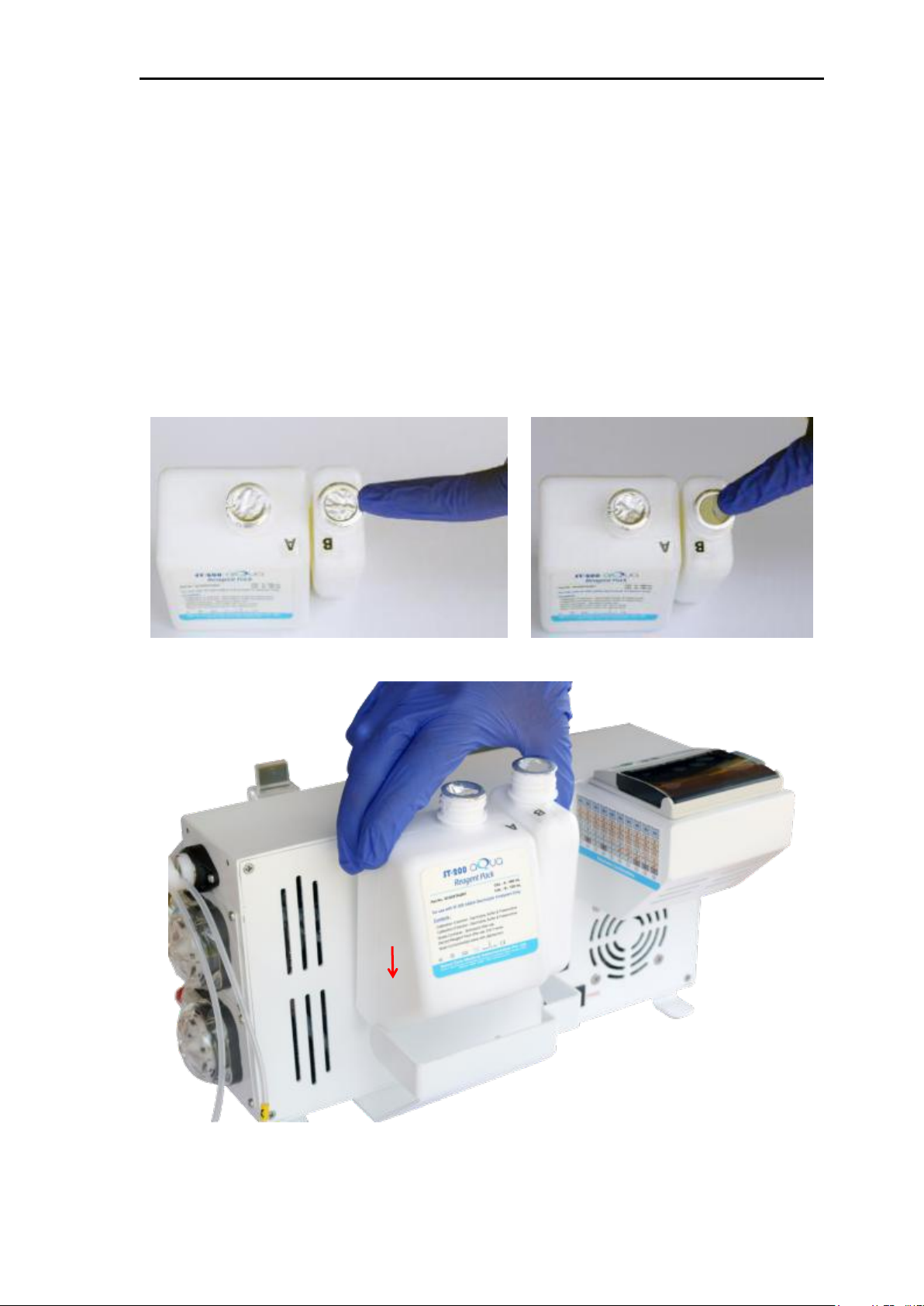
e. Reagent Pack Installation:
Reagent packs consists CAL-A and CAL-B solutions in separate containers.
Do not squeeze the reagent pack. Remove the caps and seals of the CAL-A
and CAL-B containers. Hold the reagent pack in your hand and place
reagent pack into back side slot of the analyzer; connect the CAL-A tube
cap to the CAL-A container and CAL-B tube cap to the CAL-B container
respectively as shown in below figures. Make sure that the caps should be
fixed and tighten properly.
Do not use expired reagent pack. The electrode should be exposed to
ST-200 aQua reagent all time so that it will protect electrode from getting
damaged.

ST-200 aQua Operator’s Manual
15
Figure 9
Note: Don’t place the ST-200 aQua reagent packs open to atmosphere. Because,
the solutions gets escape from the containers. Only the small vent holes on the
caps should be open for air inlet as shown below figure.
Figure 10

ST-200 aQua Operator’s Manual
16
Place the instrument into Maintenance mode.
MENU
1.DIAGNOSTICS
2.USER MENU
3.SETUP MENU
4.PARAMETERS
5.SELECT iCa UNIT
DIAGNOSTICS
1. DAILY CLEANER
2. MAINTENANCE
3. SENSORS
4. FLOW
5. HARDWARE
6. REAGENT PACK
ENTERING MAINTENANCE
Please wait …
To clean the flow path:
1. Enter in to maintenance mode and remove the electrode housing
2. Remove the reagent pack CAL-A & CAL-B flow tubes from the
3. Remove the first pump motor tubing from the roller. Take the DI
To clean the electrode blocks:
***MAINTENANCE ***
N→ Exit
C. Analyzer Restoration:
To remove or replace any ST-200 aQua components, restore the
ST-200 aQua in following order:
Press 1
↓
Press 2
Cleared liquid from the tubing
by disconnecting first pump outflow tube from the bubble detector
flow cell pin and disconnect the second pump motor inflow (red)
tube from the electrode housing.
caps and valve.
↓
↓
water in to the bold needle syringe, connect it to the tubing and
flush it with DI water and air.
If the Calibration slopes are out of range. Then, clean the electrodes
by flushing with DI water/CAL A. Do not use any plain or spring
needle to clean the electrode block.

ST-200 aQua Operator’s Manual
17
1. Use only the printer paper provided by your ST-200 aQua
2. Do not permit the printer to operate without printer paper
3. In this situation go to SETUP MENU, press default setting enter
4. Do not apply any lubricants, grease or other materials to the
D. Printer Setup:
The built-in printer will provide a permanent record of calibration and
analysis results. Other data can also be requested for printing. If required,
the printer can be turned off. (To prevent damage to the printer
mechanism, the printer must be turned off if the ST-200 aQua electrolyte
analyzer runs out of printer paper.)
Refer to the following precautions:
In order to open the printer door lift the left side lock upward direction. To
install the roll of paper into the printer, cut off the beginning section of
paper that has tape or adhesives. After installing the paper, close the cover
on the top of the housing until the door gets locked.
Use of the ST-200 aQua electrolyte analyzer printer requires some
precautions:
electrolyte analyzer distributor.
installed.
the PRINTER section and select the required option “Y” or “N” for
Printer ON /OFF. The absence of paper during printer operation
will cause premature printer failure.
printer assembly under any circumstances.
Failure to comply with the above requirements will void the printer
warranty.
Printer setup
Figure 11

ST-200 aQua Operator’s Manual
18
SENSACORE
ELECTROLYTE ANALYZER
Ver : XXXXXX
E. Power Up:
Confirm that the ST-200 aQua electrolyte analyzer voltage setting on the
rear cover matches the outlet voltage. When all the components have been
assembled, plug the ST-200 aQua electrolyte analyzer into a grounded
outlet. When the ST-200 aQua electrolyte analyzer is plugged in, the power
is ON. The Na/K/iCa/Li/pH/Cl analyzer will display,
When the ST-200 aQua electrolyte analyzer displays SYSTEM
UNCALIBRATED PLEASE CALIBRATE, installation is complete.
After initial setup, do not unplug the ST-200 aQua electrolyte analyzer
unless it must be moved to another location.
Diagram of Back view connections:
Figure 12
ST-200 aQua Operator’s Manual
19
INITIALIZING…
ACQUIRING RANGES
Please Wait…
SENSACORE
System Uncalibrated
Please Calibrate….
Na* K* iCa* Li* pH* Cl*
CALIBRATE
Y→ Continue N→ Exit
PUMPING AIR
SELF CHECK
Searching pack
OPERATING THE ANALYZER
3. Operating the Analyzer
A. Calibration
The instrument has to be calibrated when it is switched ON or it
automatically calibrates on set calibrated frequency after four hours or
eight hours as per set frequency.
Following is the calibration procedure:
A. Calibration
Switch ON the instrument
↓
Press CALIBRATE key
↓
↓
↓
↓
Press Y
Displays PUMP CALIBRATION STEPS
↓
↓
↓

20
PUMPING CAL A
PUMPING CAL A
To clean the electrodes
CAL B MEASUREMENT
Na = ______ mV
K = ______ mV
iCa= ______ mV
Li = ______ mV
pH = ______ mV
Cl = ______ mV
CAL A MEASUREMENT
Na = ______ mV
K = ______ mV
iCa= ______ mV
Li = ______ mV
pH = ______ mV
Cl = ______ mV
ST-200 aQua Operator’s Manual
↓
PUMP CAL A TEST
Pump CAL = 1137
↓
PUMPING AIR
↓
↓
↓
… 3 cycles
Air, Liquid
Air, Liquid
Air, Liquid
Displays CAL B milli volts on display
E.g.: Na= 13.46 mV
Displays CAL A milli Volts on display
E.g: Na = 33.27 mV
K = 30.64 mV
iCa = 66.31 mV
Li = 67.48 mV
pH = -31.05 mV
Cl = 66.45 mV
↓
↓
…3 cycles
Air, Liquid
Air, Liquid
Air, Liquid
K = 48.59 mV
iCa = 54.76 mV
Li = 50.77 mV
pH = -61.24 mV
Cl = 50.42 mV

ST-200 aQua Operator’s Manual
21
CALIBRATION SLOPE
Na = _______
K = _______
iCa = _______
Li = _______
pH = _______
Cl = _______
↓
Finally the instrument displays calibration slope and is ready for analysis.
E.g.: Calibration Slope
Na = 67.10
K = 61.77
iCa = 36.54
Li = 76.02
pH = 58.53
Cl = 51.54
If any parameter is not calibrated then it will show * beside that parameter in home screen.
So that, we can clearly see the status of instrument.
B. Analyze Sample
To obtain patient’s sample, follow the procedure and precautions described
under sample handling and collection. Quality control material should be
run prior to patient sample analysis.
Aspirating sample
Figure 13

ST-200 aQua Operator’s Manual
22
ANALYZE SAMPLE
Y→ Continue N→ Exit
is Sample Ready?
Y→ Continue N→ Exit
Positioning Sample
SAMPLE MEASUREMENT
Na = ______ mV
K = ______ mV
iCa= ______ mV
Li = ______ mV
pH = ______ mV
Cl = ______ mV
Processing…
Na = ______ mV
K = ______ mV
iCa= ______ mV
Li = ______ mV
pH = ______ mV
Cl = ______ mV
Once system is calibrated then it is ready to analyze patient samples,
press Analyze key
Press Y
↓
Take the sample by the pipette, drop it in the flow cell and Press Y
↓
Please wait …
↓
Sample is positioned into the sensors
Displays given SAMPLE milli Volts on display.
E.g. Na = 32.39 mV
K = 49.08 mV
iCa = 53.72 mV
Li = 56.63 mV
pH = -78.90 mV
Cl = 54.12 mV
↓
↓
↓
Displays CAL A milli Volts on display.
↓

ST-200 aQua Operator’s Manual
23
ANALYZE SAMPLE
Na = 140.9 mmol/L
K = 4.02 mmol/L
iCa = 1.25 mmol/L
Li = 1.15 mmol/L
pH = 7.516
Cl = 100.2 mmol/L
Na+
: 20.0 - 250.0 mmol/L
K+
: 0.2 - 40.0 mmol/L
iCa++
: 0 - 10.0 mmol/L
Cl-
: 20.0 - 200.0 mmol/L
Li
: 0 - 5.0 mmol/L
pH : 5.0 - 9.0
Na+
: 20.0 - 250.0 mmol/L
K+
: 0.2 - 40.0 mmol/L
iCa++
: 0 - 10.0 mmol/L
Cl-
: 20.0 - 200.0 mmol/L
Li
: 0 - 5.0 mmol/’L
pH
: 5.0 - 9.0
Eg. Na = 33.76 mV
K = 49.54 mV
iCa = 54.33 mV
Li = 48.52 mV
pH = -62.32 mV
Cl = 49.73 mV
↓
Result Outside the measurement ranges as follows will not be reported
WHOLE HAPERIN BLOOD
SERUM, PLASMA & CSF:
If iCa unit is in mg/dL, then the measurement range is 0-40 mg/dL.
C. Daily Cleaner
Execute Daily Cleaner Solution every day mandatory to remove protein
deposition from the sensors. The daily cleaner is required and is essential
for trouble-free analyzer operation. Following is the procedure of daily
cleaner.

24
Giving daily cleaner
MENU
1.DIAGNOSTICS
2.USER MENU
3.SETUP MENU
4.PARAMETERS
5.SELECT iCa UNIT
DIAGNOSTICS
1.DAILY CLEANER
2.MAINTENANCE
3.SENSORS
4.FLOW
5.HARDWARE
6.REAGENT PACK
DAILY CLEANER
is Cleaner Ready?
Y→ Continue N→ Exit
ST-200 aQua Operator’s Manual
Press MENU
Press 1
Press 1
Figure 14
↓
↓
Take the Cleaning Solution by the pipette, drop it in the flow cell and Press Y
↓
↓

ST-200 aQua Operator’s Manual
25
Aspirating
Please Wait …
CLEANING
Performing…
PUMPING AIR
PUMPING CAL A
PUMPING AIR
Clean Cycle Performed
PUMPING AIR
PUMPING CAL A
CAL B MEASUREMENT
Na = ______ mV
K = ______ mV
iCa= ______ mV
Li = _______ mV
pH = ______ mV
Cl = ______ mV
CAL A MEASUREMENT
Na = ______ mV
K = ______ mV
iCa= ______ mV
Li = ______ mV
pH = ______ mV
Cl = ______ mV
↓
↓
↓
↓
↓
↓
Displays CAL B milli Volts
↓
↓
↓
…….3 cycles of Cal B
Air, Liquid
Air, Liquid
Air, Liquid
↓
↓
….......3 cycles of Cal A
Air, Liquid
Air, Liquid
Air, Liquid
↓

26
Displays CAL A milli Volts
PUMPING AIR
PUMPING CAL A…
PUMPING CAL A
CAL B MEASUREMENT
Na = ______ mV
K = ______ mV
iCa= ______ mV
Li = ______ mV
pH = ______ mV
Cl = _______ mV
CAL A MEASUREMENT
Na = ______ mV
K = ______ mV
iCa= ______ mV
Li = ______ mV
pH = ______ mV
Cl = ______ mV
Searching pack
To clean the electrodes
ST-200 aQua Operator’s Manual
↓
↓
↓
↓
PUMP CAL A TEST
Pump CAL = 1460
↓
PUMPING AIR
↓
↓
Displays CAL B milli volts on display
↓
… 3 cycles
Air, Liquid
Air, Liquid
Air, Liquid
↓
↓
…3 cycles
Air, Liquid
Air, Liquid
Air, Liquid
Displays CAL A milli Volts on display
↓

ST-200 aQua Operator’s Manual
27
CALIBRATION SLOPE
Na = _______
K = _______
iCa = _______
Li = _______
pH = _______
Cl = _______
*** STANDBY ***
N→ Exit
EXITING
STANDBY MODE
Finally displays calibration slope & instrument is ready for analysis.
D. Standby
Placing the ST-200 aQua in STANDBY mode reduces reagents
consumption by discontinuing automatic calibrations. The analyzer does,
however, draw a small amount of calibrant A solution to prevent the
electrodes from drying out which is called as “Sipping”. To place the ST200 aQua in standby mode, press STANDBY key.
After pressing STANDBY key
Press N
Pressing Standby Button:
↓
↓
Figure 15

28
E. Sub Menus
i. Diagnostics
ST-200 aQua Operator’s Manual

29
ii. User Menu
ST-200 aQua Operator’s Manual

30
iii. Setup Menu
ST-200 aQua Operator’s Manual

31
iv. Parameters
ST-200 aQua Operator’s Manual
Note: Star (*) Indicates Blank

ST-200 aQua Operator’s Manual
32
MENU
1.DIAGNOSTICS
2.USER MENU
3.SETUP MENU
4.PARAMETERS
5.SELECT iCa UNIT
ANALYZE TYPE
1.SERUM/PLASMA
2.URINE
3.WHOLE BLOOD
4.QUALITY CONTROL
5.NON DETECTABLE
ANALYZE TYPE
URINE
N→ Exit
SETUP MENU
1.ANALYZE TYPE
2.DATE/TIME
3.PRINTER
4.PRINT-PARAMETER
5.PRINT-mV
6.PATIENT-ID
F. Analyze Urine
To obtain urine sample, follow the procedure and precautions described
under sample handling and collection.
Dilute 200 microlitres of urine specimen with 1 mL (1000 microlitres) of
urine diluent’s (this corresponds to 1 part urine and 5 parts urine
diluent’s resulting in 1:5 dilutions).
Note: In urine mode only Na, K, Cl parameters are measured but not all.
After dilution change Analyze type to URINE mode by following below steps
Press MENU
↓
↓
↓
↓

33
Aspirating urine:
ANALYZE URINE
Y→ Continue N→ Exit
is Urine Ready?
Y→ Continue N→ Exit
Positioning Urine
URINE MEASUREMENT
Na = ______ mV
K = ______ mV
Cl = ______ mV
ST-200 aQua Operator’s Manual
Figure 16
Set instrument in Urine type as follows:
↓
Press Y
Take the diluted urine solution by the pipette, drop it in the flow cell and Press Y
↓
Please Wait …
↓
↓
↓

ST-200 aQua Operator’s Manual
34
Processing …
Na = ______ mV
K = _____ mV
Cl =______ mV
ANALYZE URINE
Na = 379.90 mmol/L
K = 78.22 mmol/L
Cl = 357.76 mmol/L
Na+
35 - 1000 mmol/L
K+
50 - 200 mmol/L
Cl-
25 - 500 mmol/L
1. Sample Results
2. QC Results
3. Urine Results
milli Volts of urine sample will be display.
e.g. Na = 10.15 mV
K = 76.56 mV
Cl = 64.26 mV
↓
↓
milli Volts of CAL A will be displayed on the display.
e.g. Na = 33.68 mV
K = 49.47 mV
Cl = 49.80 mV
↓
Result Outside the measurement ranges as follows will not be
reported
URINE RANGE
G. Stored Results
Press MENU 2. USER MENU 4. PRINT STORED RESULTS
The ST-200 aQua has data storage and recovery capability of 2 Lakhs+
patients results, 25000 Urine results and 100 QC results. All results from
the oldest day will be deleted when the storage capacity has been reached.
Therefore it is important to request a printout of data as the storage
capacity is approached if you desire to retain a copy of all the stored
results.

ST-200 aQua Operator’s Manual
35
STORED SAMPLE RESULTS
Please Enter ‘5’ Dig
Patient ID :
XXXXX
Y→ Continue N→ Clear
STORED SAMPLE RESULTS
Searching ...
P.ID: XXXXX
Na = _______
K = _______
iCa = ______
Cl = ______
Li = _______
pH = _______
Y → Print N → Exit
SEARCHING PATIENT ID:
ST-200 aQua is having a feature to search patient results by
entering Patient ID. User should enter patient ID (up to 5 numeric digits),
after Pressing Y it will display results on screen, user can take print out by
pressing Y button again.
Press Y
↓
↓
Press ‘Y’ to print displayed result or press ‘N’ to exit.
H. Reagent Pack Consumption
The ST-200 aQua monitors fluid consumption automatically. The
percentage of the reagent pack that has been consumed can be checked
whenever required by answering ‘Y’ to REAGENT PACK CONSUMPTION,
the percentage of the reagent pack that has been left is displayed and
printed. ST-200 aQua will instruct the operator to change pack by
displaying message as INSUFFICIENT PACK PLEASE REPLACE, when 90%
of the reagent pack solution has been consumed. Please make a note that
due to variations in pump tubes elasticity analyzer gives ‘Air in CAL-A’ or
‘Air in CAL-B’ if Reagent pack shows solution left as 10-15 %.
Reagent Pack Installation
Reagent packs consists CAL-A and CAL-B solutions in separate containers.
Do not squeeze the reagent pack. Remove the caps and seals of the CAL-A
and CAL-B containers. Hold the reagent pack in your hand and place
reagent pack into back side slot of the analyzer; connect the CAL-A tube
cap to the CAL-A container and CAL-B tube cap to the CAL-B container

ST-200 aQua Operator’s Manual
36
a) Diagnostics
MENU
1.DIAGNOSTICS
2.USER MENU
3.SETUP MENU
4.PARAMETERS
5.SELECT iCa UNIT
respectively as shown in below figures. Make sure that the caps should be
fixed and tighten properly.
Do not use expired reagent pack. The electrode should be exposed to
ST-200 aQua reagent all time so that it will protect electrode from getting
damage.
Incompatible pack
If unauthorized reagent pack is trying to use in analyzer then it will
display Incompatible pack on screen. Use authorized reagent pack.
I. Quality control
Use ST-200 aQua Quality controls on a daily basis to verify the accuracy
and precision of your analyzer. If the ST-200 aQua is calibrated and your
quality control results are within specified range, you can be confident in
the results obtained.
Run all the control levels daily. Data may be stored in memory for future
statistical analysis.
To perform quality control sample, set up ANALYZE TYPE as QC in set up
menu. Refer to the Quality control ranges in performance certificate
provided with the quality control solutions.
Do not use control materials containing ethylene glycol and other stabilizer,
as they may give incorrect results and/or damage the ST-200 aQua
electrode blocks.
J. Operator Functions
Following are the steps to operate ST-200 aQua in the form of flow
diagram.
1. DAILY CLEANER:
The diagnostics routine permits the operator to check and test key
operating functions of the ST-200 aQua.
Following is the flow chart of diagnostics menu.
Press MENU
Press 1

ST-200 aQua Operator’s Manual
37
DIAGNOSTICS
1.DAILY CLEANER
2.MAINTENANCE
3.SENSORS
4.FLOW
5.HARDWARE
6.REAGENT PACK
DAILY CLEANER
is Cleaner Ready?
Y→ Continue N→ Exit
Aspirating
Please Wait …
CLEANING
Performing…
PUMPING AIR
PUMPING CAL A
PUMPING AIR
Clean Cycle Performed
PUMPING AIR
PUMPING CAL A
CAL B MEASUREMENT
Na = ______ mV
K = ______ mV
iCa= ______ mV
Li = _______ mV
pH = ______ mV
Cl = ______ mV
↓
Press 1
↓
↓
↓
Take the Cleaning Solution by the pipette and drop it in the flow cell and Press Y
↓
↓
↓
↓
↓
↓
↓
↓
↓
…….3 cycles of Cal B
Air, Liquid
Air, Liquid
Air, Liquid
↓
Displays CAL B milli Volts

38
CAL A MEASUREMENT
Na = ______ mV
K = ______ mV
iCa= ______ mV
Li = ______ mV
pH = ______ mV
Cl = ______ mV
Displays CAL A milli Volts
PUMPING AIR
PUMPING CAL A…
PUMPING CAL A
CAL B MEASUREMENT
Na = ______ mV
K = ______ mV
iCa= ______ mV
Li = ______ mV
pH = ______ mV
Cl = _______ mV
CAL A MEASUREMENT
Searching pack
ST-200 aQua Operator’s Manual
↓
….......3 cycles of Cal A
Air, Liquid
Air, Liquid
Air, Liquid
↓
↓
↓
↓
To clean the electrodes
↓
PUMP CAL A TEST
Pump CAL = 1460
↓
PUMPING AIR
↓
↓
↓
… 3 cycles
Air, Liquid
Air, Liquid
Air, Liquid
Displays CAL B milli volts on display
↓
↓
…3 cycles
Air, Liquid
Air, Liquid
Air, Liquid

ST-200 aQua Operator’s Manual
39
Na = ______ mV
K = ______ mV
iCa= ______ mV
Li = ______ mV
pH = ______ mV
Cl = ______ mV
CALIBRATION SLOPE
Na = _______
K = _______
iCa = _______
Li = _______
pH = _______
Cl = _______
MENU
1.DIAGNOSTICS
2.USER MENU
3.SETUP MENU
4.PARAMETERS
5.SELECT iCa UNIT
DIAGNOSTICS
1.DAILY CLEANER
2.MAINTENANCE
3.SENSORS
4.FLOW
5.HARDWARE
6.REAGENT PACK
ENTERING MAINTENANCE
Please wait …
Displays CAL A milli Volts on display
↓
Finally displays calibration slope & instrument is ready for analysis.
2. MAINTENANCE:
Whenever operator wants to switch off the instrument then operator
should activate maintenance mode then he can switch off the instrument.
Press MENU
Press 1
↓
Press 2
Cleared liquid from the tubing
↓
↓

40
Press N it will display
EXITING MAINTENANCE
Please wait …
SENSACORE
System Uncalibrated
Please Calibrate
Na* K* iCa* Li* pH* Cl*
MENU
1.DIAGNOSTICS
2.USER MENU
3.SETUP MENU
4.PARAMETERS
5.SELECT iCa UNIT
DIAGNOSTICS
1.DAILY CLEANER
2.MAINTENANCE
3.SENSORS
4.FLOW
5.HARDWARE
6.REAGENT PACK
SENSORS
1.SENSOR CAL A-mV
2.SENSOR CAL B-mV
N→ Exit
CAL A MEASUREMENT
***MAINTENANCE ***
N→ Exit
Press Calibrate Key.
ST-200 aQua Operator’s Manual
↓
↓
3. SENSORS:
Sensors is used to check mV of the electrodes for each reagent separately
Press MENU
Press 1
Press 3
↓
↓
Press1
↓
SENSOR CAL A-mV
↓

41
SENSOR CAL A-mV
Na = ______ mV
K = ______ mV
iCa = ______ mV
Li = ______ mV
pH = ______ mV
Cl = ______ mV
Displays milli Volts of CAL A
SENSORS
1. SENSOR CALA-mV
2. SENSOR CAL B-mV
CAL B MEASUREMENT
SENSOR CAL B-mV
Na = ______ mV
K = ______ mV
iCa = ______ mV
Li = ______ mV
pH = ______ mV
Cl = ______ mV
MENU
1.DIAGNOSTICS
2.USER MENU
3.SETUP MENU
4.PARAMETERS
5.SELECT iCa UNIT
Press N
Press 2
ST-200 aQua Operator’s Manual
… 3 cycles of Cal A
Air, Liquid
Air, Liquid
Air, Liquid
↓
↓
↓
SENSOR CAL B-mV
↓
…. 3 cycles of Cal B
Air, Liquid
Air, Liquid
Air, Liquid
↓
Displays milli Volts of CAL B on display.
4. FLOW:
It is used when, inserting new reagent pack or troubleshooting flow issues in instrument
by priming CAL A, CAL B & ALL.
Press 1
↓

42
DIAGNOSTICS
1.DAILY CLEANER
2.MAINTENANCE
3.SENSORS
4.FLOW
5.HARDWARE
6.REAGENT PACK
Press 4
FLOW
1.REAGENT PRIMING
2.PUMP CALIBRATION
3.VALVE TEST
N→ Exit
REAGENT PRIMING
1.PRIME CAL A
2.PRIME CAL B
3.PRIME ALL
N→ Exit
PRIMING CAL A
Please wait …
PRIMING CAL A
Priming Completed
N→ Exit
REAGENT PRIMING
1.PRIME CAL A
2.PRIME CAL B
3.PRIME ALL
N→ Exit
PRIMING CAL B
Please wait …
Reagent Priming
Press 1
ST-200 aQua Operator’s Manual
↓
↓
↓
Press 1
↓
Air is aspirated followed by CAL A through electrode housing.
↓
↓
Press 2
Air is aspirated followed by CAL B through electrode housing.
↓

43
PRIMING CAL B
Priming Completed
N→ Exit
Press N
PRIMING CAL B
Priming …
REAGENT PRIMING
1.PRIME CAL A
2.PRIME CAL B
3.PRIME ALL
N→ Exit
PRIMING CAL B
Please wait …
PRIMING CAL A
Please wait….
PRIMING CAL A
Priming Completed
N→ Exit
REAGENT PRIMING
1.PRIME CAL A
2.PRIME CAL B
3.PRIME ALL
N→ Exit
FLOW
1.REAGENT PRIMING
2.PUMP CALIBRATION
3.VALVE TEST
N→ Exit
PUMPING AIR
Press 3
ST-200 aQua Operator’s Manual
↓
↓
↓
↓
Air is aspirated followed by CAL B through electrode housing.
↓
Press N
↓
Air is aspirated followed by CAL A through electrode housing.
↓
Pump Calibration
Press 2
↓

ST-200 aQua Operator’s Manual
44
PUMPING CAL A
PUMP CAL A TEST
Pump CAL = 1545
N→ Exit
FLOW
1.REAGENT PRIMING
2.PUMP CALIBRATION
3.VALVE TEST
N→ Exit
VALVE TEST
1.CAL A FLOW
2.CAL B FLOW
3.CAL A/B In Flow
4.AIR FLOW
N→ Exit
CAL A FLOW ON
60
N→ STOP
CAL A FLOW OFF
N→ Exit
VALVE TEST
1.CAL A FLOW
2.CAL B FLOW
3.CAL A/B In Flow
4.AIR FLOW
N→ Exit
↓
↓
Instrument performs pump calibration using Cal A & displays the pump steps.
VALVE TEST:
VALVE TEST is used to clean the flow path of valve, by using DI water & syringe
Press 3
↓
↓
Press 1
Clean the CAL A flow path of valve before counter reaches ‘0’.
↓
Press N
Press N
↓

ST-200 aQua Operator’s Manual
45
CAL B FLOW ON
60
N→ STOP
CAL B FLOW OFF
N→ Exit
VALVE TEST
1.CAL A FLOW
2.CAL B FLOW
3.CAL A/B In Flow
4.AIR FLOW
N→ Exit
CAL A/B In Flow ON
60
N→ STOP
CAL A/B In Flow OFF
N→ Exit
VALVE TEST
1.CAL A FLOW
2.CAL B FLOW
3.CAL A/B In Flow
4.AIR FLOW
N→ Exit
AIR FLOW ON
60
N→ STOP
↓
Press 2
Clean the CAL B flow path of valve before counter reaches ‘0’.
↓
Press N
Press N
↓
↓
Press 3
Clean the CAL A/B flow path (inlet) of valve and the tubing of first pump motor before
counter reaches ‘0’.
Press N
↓
↓
Press 4
Clean the flow cell which is present on the top of the bubble detector before counter
reaches ‘0’.
↓

46
Press N
AIR FLOW OFF
N→ Exit
MENU
1.DIAGNOSTICS
2.USER MENU
3.SETUP MENU
4.PARAMETERS
5.SELECT iCa UNIT
DIAGNOSTICS
1.DAILY CLEANER
2.MAINTENANCE
3.SENSORS
4.FLOW
5.HARDWARE
6.REAGENT PACK
HARDWARE
1.SAMPLE DETECTOR
2.PUMP MODULE
3.SOFTWARE VERSION
N→ Exit
SAMPLE DETECTOR TEST
PUMPING AIR
SAMPLE DETECTOR TEST
Air Detected
PUMPING LIQUID
Liquid Detected
N→ Exit
5. HARDWARE:
Press 1
ST-200 aQua Operator’s Manual
↓
↓
Press 5
Sample detector
Press 1
↓
↓
↓
↓
Liquid flows through bubble detector
↓

ST-200 aQua Operator’s Manual
47
HARDWARE
1.SAMPLE DETECTOR
2.PUMP MODULE
3.SOFTWARE VERSION
N→ Exit
PUMP SPEED → FAST
PUMP SPEED → SLOW
N→ Exit
HARDWARE
1.SAMPLE DETECTOR
2.PUMP MODULE
3.SOFTWARE VERSION
N→ Exit
SOFTWARE VERSION:
XXXXX
Date : DD-MM-YYYY
N→ Exit
MENU
1.DIAGNOSTICS
2.USER MENU
3.SETUP MENU
4.PARAMETERS
5.SELECT iCa UNIT
Pump module functionality:
Press 2
Both Pump rotates and checks its statuses.
↓
↓
Software version:
Press 3
↓
It shows the version & date
6. REAGENT PACK:
It shows the information of reagent pack like consumption, reagent pack lot no. or pack
volume & information about CAL A, CAL B concentrations.
Press 1
↓

48
DIAGNOSTICS
1.DAILY CLEANER
2.MAINTENANCE
3.SENSORS
4.FLOW
5.HARDWARE
6.REAGENT PACK
Press 6
REAGENT PACK
1.REAGENT PACK ID
2.REAGENT PACK INFO
3.REAGENT PACK
CONSUMPTION
REAGENT PACK ID
:BE91132C000007E0
OEM/NON OEM:NON OEM
DISTRIBUTOR ID: XX1
LOT NO: XXXXX
PACK VOLUME: 450 mL
N→ Exit
REAGENT PACK
1.REAGENT PACK ID
2.REAGENT PACK INFO
3.REAGENT PACK
CONSUMPTION
REAGENT PACK INFO
MANUFACTURED ON:
******
EXPIRY DATE:
******
Y→ Continue
Press 1
ST-200 aQua Operator’s Manual
↓
↓
REAGENT PACK ID
Please Wait…
↓
Press N
Press 2
↓
REAGENT PACK INFO
Please Wait …
↓
Reagent pack manufacturing and expiry date is displayed.
Press Y
↓

ST-200 aQua Operator’s Manual
49
CAL A CONCENTRATION
Na : 148.0
K : 4.10
iCa : 1.40
Cl : 127.00
Li : 0.30
pH : 7.400
CAL B CONCENTRATION
Na : 75.00
K : 2.10
iCa : 2.90
Cl : 60.00
Li : 2.00
pH : 6.78
N→ Exit
REAGENT PACK
1.REAGENT PACK ID
2.REAGENT PACK INFO
3.REAGENT PACK
CONSUMPTION
REAGENT PACK CONSUMPTION
Please Wait…
REAGENT PACK CONSUMPTION
Solution left : 98%
N→ Exit
NO OF SAMPLES : 10
TOTAL SAMPLES : 253
N→ Exit
Concentration of CAL A is displayed.
Press Y
Concentration of CAL B is displayed.
Press N
↓
Press 3
↓
↓
Consumption of reagent pack is displayed in %.
Press N
↓
No. of samples means total samples performed with the particular reagent pack since
from pack installation.
Total samples means total samples performed in the analyzer since from installation.

ST-200 aQua Operator’s Manual
50
MENU
1.DIAGNOSTICS
2.USER MENU
3.SETUP MENU
4.PARAMETERS
5.SELECT iCa UNIT
USER MENU
1.NORMAL RANGES
2.CALIBRATION FREQUENCY
3.SIPPING FREQUENCY
4.PRINT STORED RESULTS
5.AUTO-STANDBY
6.CORRECTION FACTOR
RESETTING RANGES
Please wait…..
AQUIRING RANGES
Please wait….
MENU
1.DIAGNOSTICS
2.USER MENU
3.SETUP MENU
4.PARAMETERS
5.SELECT iCa UNIT
NORMAL RANGES
1.RESET RANGES
2.USER SETTINGS
b) USER MENU
Users menu permits the operator to check and test key operating functions of the
ST-200 aQua.
Following is the flow chart of users menu.
Press 2
↓
Press 1
↓
Please make a note that if you press the RESET RANGES then instrument reset all the
ranges to Default factory settings.
Press 1
↓
↓
RANGES RESETTED
↓
NORMAL RANGES: USER SETTINGS
Press 2
↓

51
USER MENU
1.NORMAL RANGES
2.CALIBRATION FREQUENCY
3.SIPPING FREQUENCY
4.PRINT STORED RESULTS
5.AUTO-STANDBY
6.CORRECTION FACTOR
Press 1
USER SETTINGS
1.SAMPLE RANGES
2.URINE RANGES
3.QC1 RANGES
4.QC2 RANGES
5.QC3 RANGES
SAMPLE RANGES
1.Na
2.K
3.iCa
4.Cl
5.Li
6.pH
N→ Exit
SAMPLE RANGES
Na MAX : 150.00
Na MIN : 135.00
Y→ Edit N→ Exit
-------EDIT-------
Na MAX : 150.00
Na MIN : 135.00
1→ Mx 2→ Mn N→ Exit
Na MAX :
Y→ Save N→ Clear
NORMAL RANGES
1.RESET RANGES
2.USER SETTINGS
Press 2
ST-200 aQua Operator’s Manual
↓
↓
Press 1
↓
Press required parameter to be changed and enter its maximum and minimum ranges.
Example:
Press 1
Press Y
↓
Press 1
Enter the value and press ‘ Y ‘ to Save and ‘ N ‘ to Clear.
Similarly, for all the parameters in Sample, Urine & QC Ranges.
↓

ST-200 aQua Operator’s Manual
52
USER MENU
1.NORMAL RANGES
2.CALIBRATION FREQUENCY
3.SIPPING FREQUENCY
4.PRINT STORED RESULTS
5.AUTO-STANDBY
6.CORRECTION FACTOR
CALIBRATION FREQUENCY
STATUS : 4 HOURS
Y→ 4 HOURS N→ 8 HOURS
SIPPING FREQUENCY
STATUS : 30 MINS
Y→ 30 MINS N→ 1 HOUR
USER MENU
1.NORMAL RANGES
2.CALIBRATION FREQUENCY
3.SIPPING FREQUENCY
4.PRINT STORED RESULTS
5.AUTO STANDBY
6.CORRECTION FACTOR
CALIBRATION FREQUENCY
Instrument will perform automatic calibration for every 4 hours /8 hours for good
performance of the instrument.
Press 2
↓
Press Y to select 4 hours or N to select 8 hours calibration frequency.
SIPPING FREQUENCY
For every 30min /1 hour instrument takes 400ul of liquid to make electrodes wet
this is called sipping. Here we can select the sipping time frequency.
Press 3
↓

ST-200 aQua Operator’s Manual
53
USER MENU
1.NORMAL RANGES
2.CALIBRATION FREQUENCY
3.SIPPING FREQUENCY
4.PRINT STORED RESULTS
5.AUTO STANDBY
6.CORRECTION FACTOR
PRINT STORED RESULTS
1.Sample Results
2.QC Results
3.Urine Results
STORED SAMPLE RESULTS
Please Enter ‘5’ Dig
Patient ID:
XXXXX
Y→ Continue N→ Clear
P.ID :XXXXX
Na= 135.89
K = 4.215
iCa= 1.083
Cl = 92.559
Li= 0.00
pH= 7.06
Y→ Print N→ Exit
PRINT RESULTS
Press 4
PRINT STORED SAMPLE RESULTS:
Press 1
↓
Enter Patient ID maximum up to 5 numeric digits which you want to search
Press Y
↓
STORED SAMPLE RESULTS
Searching …
↓
Press “Y” to print displayed result or press “N” to shift to next result screen.
PRINT STORED QC RESULTS:
CONTROL in settings menu.
For storing QC results separately user must select ANALYZE TYPE to QULATIY

ST-200 aQua Operator’s Manual
54
PRINT STORED RESULTS
1.Sample Results
2.QC Results
3.Urine Results
-- QC Samples --
1. Last 1-25 samples
2. Last 26-50 samples
3. Last 51-75 samples
4. Last 76-100 samples
N→ Exit
RESULT : 00
Y→ Next N→ Exit
RESULT : 01
Na= 135.89
K = 4.215
iCa= 1.083
Cl = 92.559
Li= 0.00
pH= 7.06
Y→ Print N→ Exit
RESULT : 01
Na= 135.89
K = 4.215
iCa= 1.083
Cl = 92.559
Li= 0.00
pH= 7.06
Y→ Next N→ Exit
Press 2
↓
Depending upon the result required select the range option.
Press 1
↓
↓
Press Y
Press ‘ Y ‘ to print displayed result or press ‘ N ‘ to shift to next result screen.
Press N
Press ‘ Y ‘ to display next result or press ‘ N ‘ to Exit.
Press ‘ Y ‘
↓

ST-200 aQua Operator’s Manual
55
RESULT : 02
Na= 133.54
K = 4.129
iCa= 1.083
Cl = 94.645
Li= 0.00
pH= 7.09
Y→ Print N→ Next
PRINT STORED RESULTS
1.Sample Results
2.QC Results
3.Urine Results
STORED URINE RESULTS
Please Enter ‘5’ Dig
Patient ID:
XXXXX
Y→ Continue N→ Clear
STORED SAMPLE RESULTS
Searching…
P.ID :XXXXX
Na= 382.28
K = 70.99
Cl= 374.82
Y→ Print N→ Exit
Press ‘ Y ‘ to print displayed result or press ‘ N ‘ to obtain next result.
PRINT STORED URINE RESULTS:
Press 3
↓
Enter Patient Id maximum up to 5 numeric digits which you want to search
Press Y
Press ‘ Y ‘ to print displayed result or press ‘ N ‘ to shift to next result screen.
AUTO STANDBY
which depends on calibration frequency. If calibration frequency is 4 hrs, calibration
occurs after 4 hrs from the previous calibration after that analyzer automatically goes into
STANDBY mode.
↓
↓
AUTO STANDBY option is used to ON the STANDBY mode automatically,

56
MENU
1.DIAGNOSTICS
2.USER MENU
3.SETUP MENU
4.PARAMETERS
5.SELECT iCa UNIT
Press 2
USER MENU
1.NORMAL RANGES
2.CALIBRATION FREQUENCY
3.SIPPING FREQUENCY
4.PRINT STORED RESULTS
5.AUTO-STANDBY
6.CORRECTION FACTOR
AUTO-STANDBY
STATUS : ON
Y→ON N→OFF
USER MENU
1.NORMAL RANGES
2.CALIBRATION FREQUENCY
3.SIPPING FREQUENCY
4.PRINT STORED RESULTS
5.AUTO-STANDBY
6.CORRECTION FACTOR
SLOPE/INTERCEPT
1. Na
2. K
3. Cl
4. iCa
5. Li
6. pH
SLOPE/INTERCEPT
SLOPE FACTOR:
[ 01.00 ]
INTERCEPT:
+[ 00.00 ]
Y→ SET N→ Next
Press 5 for Auto-Standby
ST-200 aQua Operator’s Manual
↓
↓
Press Y to On and N to Off
CORRECTION FACTOR
Press 6
Press 1
↓
↓
Note: - By default Slope factor value is 01.00 & Intercept is 00.00.

ST-200 aQua Operator’s Manual
57
SLOPE FACTOR:
Slope factor is used for multiplying the factor with the result obtained.
Figure 17
In the above graph, green line indicates the normal/reference state (All the control
levels lie with its range as per the Q.C sheet provided in the Q.C box) and red line
indicates the error/out-off state (Electrodes are reading either higher or lower).
After running all the three controls only, we can confirm that whether slope
factor/intercept should be added depending upon its readings.
In the above graph level-1, level-2 and level-3 of any parameter is reading on
higher side. In this case we have to add slope factor between 0.5 to 1. So, that level-1,
level 2 and level 3 results will be multiplied by that factor.
E.g.: In the above graph, when all the three Q.C levels are analyzed. We have got Na on
higher side. In this case, we have to insert slope factor of 0.92. Now, 0.92 will be
multiplied with the result of Na (e.g.: 130*0.92=119).
After adding slope factor we should run all the three controls and verify whether
selected parameter (parameter which needed correction) lie within its range. Slope factor
should be added and verified until the parameter lie in its range.
If level-1, level-2 and level-3 of Na is reading on lower side (i.e. reverse of above
case). Then, we have to add slope factor between 1to 1.5. So, that level-1, level 2 and level
3 results will be multiplied by that factor.
Y = m X + C
Where, m = slope. If we add slope factor from 0.5 to 1, then our output(Y) will be
decreased. Since, slope factor will be multiplied with X (obtained result). Similarly, if we
add slope factor from 1 to 1.5, then our output will be increased. Since, slope factor will
be multiplied with X (obtained result).
Note: Slope factor ranges from 0.5 to 1.5 for Na, K, iCa, pH, Li, Cl parameters individually.

ST-200 aQua Operator’s Manual
58
SLOPE/INTERCEPT
SLOPE FACTOR:
[ 01.00 ]
INTERCEPT:
+ [ 00.00 ]
Y→ ‘+’ N→ ‘- ‘
INTERCEPT:
Intercept is used if all the three control values read either higher or lower.
Figure 18
(i.e.) y = mx + c
Where m is the slope of the line and C is the y-intercept, which is the y-coordinate of
the location where line crosses the y axis.
For increasing/decreasing all the control values to desired level we have to select + or -10
variation for Na, Cl & + or – 0.5 variation in K, pH, iCa, Li. In the above graph of
intercept, Na is reading all the three control levels higher approximately by 10. In this
case we have to subtract intercept as 10.00 and verify it by running all three controls.
Similarly, for all the parameters intercept can be added according to their requirement
and respectively intercept ranges.
Note: - By default Slope factor value is 01.00 & Intercept is 00.00
Select + or – 10 variation for Na, Cl & + or – 0.5 variation in K, pH, iCa, Li according to
the necessity for result.
Press N

ST-200 aQua Operator’s Manual
59
SLOPE/INTERCEPT
1. Na
2. K
3. Cl
4. iCa
5. Li
6. pH
MENU
1.DIAGNOSTICS
2.USER MENU
3.SETUP MENU
4.PARAMETERS
5.SELECT iCa UNIT
SETUP MENU
1.ANALYZE TYPE
2.DATE/TIME
3.PRINTER
4.PRINT-PARAMETER
5.PRINT-mV
6.PATIENT-ID
ANALYZE TYPE
1.SERUM/PLASMA
2.URINE
3.WHOLE BLOOD
4.QUALITY CONTROL
5.NON DETECTABLE
ANALYZE TYPE
SERUM/PLASMA
N→ Exit
ANALYZE TYPE
1.SERUM/PLASMA
2.URINE
3.WHOLE BLOOD
4.QUALITY CONTROL
5.NON DETECTABLE
C) Setup Menu
Setup menu permits the operator to check and test key operating functions of the ST-200
aQua.
Following is the flow chart of setup menu.
Press 3
Press 1
Press 1
↓
↓
↓
Press N
Press 2
↓

60
ANALYZE TYPE
URINE
N→ Exit
Press N
ANALYZE TYPE
1.SERUM / PLASMA
2.URINE
3.WHOLE BLOOD
4.QUALITY CONTROL
5.NON DETECTABLE
ANALYZE TYPE
WHOLE BLOOD
N→ Exit
ANALYZE TYPE
1.SERUM / PLASMA
2.URINE
3.WHOLE BLOOD
4.QUALITY CONTROL
5.NON DETECTABLE
ANALYZE TYPE
QUALITY CONTROL
N→ Exit
ANALYZE TYPE
1.SERUM / PLASMA
2.URINE
3.WHOLE BLOOD
4.QUALITY CONTROL
5.NON DETECTABLE
ANALYZE TYPE
NON DETECTABLE
N→ Exit
Press 3
Press N
ST-200 aQua Operator’s Manual
↓
Press 4
Press N
Press 5
Non Detectable
↓
↓
sometimes bubble detector will not detect sample gives air in sample, and then change
the mode to NON DETECTABLE & run sample. Please make a note that after completion
of sample analyze setup analyze to SERUM mode.
If there is any sample which consists of high Bilirubin (Lipemic samples)

ST-200 aQua Operator’s Manual
61
SETUP MENU
1.ANALYZE TYPE
2.DATE/TIME
3.PRINTER
4.PRINT -PARAMETERS
5.PRINT-mV
6.PATIENT-ID
DATE/TIME
DATE : MM DD, YYYY
TIME : HH:MM:SS
Y→ SET N→ NEXT
Select month
June
Y→ SET N→ NEXT
Select date
23
Y→ SET
Select Year
17
Y→ SET
DATE/TIME
DATE : June 23, 2017
TIME : ---:---:---
Y→ SET N→ NEXT
Date / Time:
By using this option user can change the Date & Time of the instrument. By
using Y button we can select the field which we want to change & by using N button we
can change the field.
Press 2
↓
Press Y
Press Y
Press Y
Set the Time: Hours
Select Hour:
11
Y→ SET
62
DATE/TIME
DATE : June 23, 2017
TIME : 11:---:---
Y→ SET N→ NEXT
Set the Time: Minutes
DATE/TIME
DATE : June 23, 2017
TIME : 11:47:---
Y→ SET N→ NEXT
DATE/TIME
DATE : June 23, 2017
TIME : 11:47:30
Y→SET N→NEXT
SETUP MENU
1.ANALYZE TYPE
2.DATE/TIME
3.PRINTER
4.PRINT-PARAMETERS
5.PRINT-mV
6.PATIENT-ID
ST-200 aQua Operator’s Manual
Select Minute:
47
Y→ SET
Set the Time: Seconds
Press N
The date and time has been set.
PRINTER:
User can switch OFF the printer if not required.
Select Seconds:
30
Y→ SET
↓

ST-200 aQua Operator’s Manual
63
PRINTER
STATUS : ON
Y→ON N→OFF
SETUP MENU
1.ANALYZE TYPE
2.DATE/TIME
3.PRINTER
4.PRINT-PARAMETERS
5.PRINT-mV
6.PATIENT-ID
PRINT PARAMETERS
1.Na
2.K
3.Cl
4.iCa
5.Li
Y→ Next N→ Exit
SETUP MENU
1.ANALYZE TYPE
2.DATE/TIME
3.PRINTER
4.PRINT-PARAMETERS
5.PRINT-mV
6.PATIENT-ID
PRINT – mV
STATUS : ON
Y→ON N→OFF
Press 3
Press Y to ON, press N to OFF the printer status
Press 4
↓
If your required parameter is present in this screen then select the parameter by pressing
appropriate number, if not then press Y button to see more parameters.
↓
PRINT PARAMETERS
6.pH
7.All
N→ Exit
Press corresponding number for parameters details which to be analyzed and printed
And press N to exit.
Print –mV:
If user don’t want to print mill volts (mV) of CAL A, CAL B but only wants results
then Print –mV can be deselected.
Press 5
↓
Press Y to ON, press N to OFF the PRINT – mV status
ST-200 aQua Operator’s Manual
64
SETUP MENU
1.ANALYZE TYPE
2.DATE/TIME
3.PRINTER
4.PRINT-PARAMETERS
5.PRINT-mV
6.PATIENT-ID
PATIENT-ID
- - - - - - - - - - -
STATUS : OFF
- - - - - - - - - -
1→ MANUAL 2→ AUTO
N→ OFF
We can set manual & auto status for PATIENT ID (i.e.) press 2 for AUTO status, it
In MANUAL status (i.e.) we have to provide PATIENT ID for each sample as per
Press Menu
1. K Na * * * *
2. K Na * * * Cl
3. K Na iCa * * *
4. K Na iCa * * Cl
5. K Na iCa Li * *
6. K Na iCa pH * *
Y → Next N→ Exit
MENU
1.DIAGNOSTICS
2.USER MENU
3.SETUP MENU
4.PARAMETERS
5.SELECT iCa UNIT
PATIENT ID:
Patient ID should be ON to get previous stored results. If patient –ID option is
deselected then instrument will not ask to enter patient ID while analyzing.
Press 6
↓
takes the PATIENT ID spontaneously in serial wise for each sample without giving
PATIENT ID.
requirement.
D) Parameters:
Depending upon requirement change model of the analyzer ensure that
Electrode blocks stacking should be done according to the order in
parameter option.
Where * indicates blank electrode.
Press 4
↓

ST-200 aQua Operator’s Manual
65
1. K Na iCa Li pH *
2. K Na iCa pH * Cl
3. K Na iCa Li * Cl
4. K Na iCa Li pH Cl
N→ Exit
By selecting the parameters as per requirement & arrange the
MENU
1.DIAGNOSTICS
2.USER MENU
3.SETUP MENU
4.PARAMETERS
5.SELECT iCa UNIT
iCa UNITS
UNIT : mmol/L
Y → mg/dL N→ mmol/L
If your required model is present in this screen then select the model by
pressing appropriate number, if not then press Y button to see more
models
electrode blocks as per parameters.
Note: In 5thModel Li parameter depends on Na and iCa parameters,
If Na or iCa or both Na & iCa not calibrated, Li won’t be analyzed.
E) Select iCa Unit:
Depending up on user requirement can select iCa measuring units to
mg/dL or mmol/L. By default it is in mmol/L.
Press: MENU
Press 5
↓

ST-200 aQua Operator’s Manual
66
1. Collect the specimen by venipuncture into a Lithium-Heparin or
2. Mix the specimen by gently inverting and rotating the tube. Do not
3. Analyze specimens within one hour of collection; beyond this time
4. For analysis on Na/K/iCa/Cl/Li/pH analyzer, specimens should be
1. Collect the specimen by venipuncture into an untreated (red-topped)
2. Let blood stand for 20-30 minutes to allow clot formation.
3. Rim the clot with an applicator stick, then centrifuge the tube for
4. Serum may be analyzed immediately or stored at 4ºC for 24 hours or
HANDLING AND COLLECTION
4. Sample Handling and Collection
Warning
other pathogens. Treat all specimens and collection devices and tools as
biohazardous materials.
A. Whole Blood
Whole blood specimens should be drawn carefully to avoid hemolysis.
Elevated potassium values may indicate a hemolyzed specimen; if
hemolysis is suspected, a new sample should be drawn and analyzed.
Finger stick methods should be avoided since they can result in elevated
potassium values.
: Human body fluid specimens may be contaminated with HIV or
Sodium-Heparin (green-topped) evacuated blood collection tube. For
Lithium analysis, a sodium-Heparin (green-topped) tube must be
used. Do not use ammonium heparin, EDTA or NaF tubes. Note the
time of collection.
shake.
falsely elevated potassium levels may be obtained.
measured within 3-5 minutes.
B. Serum
tube. Fill the tube to at least 2/3 of the total volume. Note the time
of collection.
10-15 minutes and transfer the serum to a clean specimen tube.
frozen at -20ºC for up to one week. Sample must be brought to room
temperature and mixed well before assaying.

ST-200 aQua Operator’s Manual
67
1. Collect the specimen by venipuncture into a Sodium-Heparin (green-
2. Mix the specimen by gently inverting the tube. Do not shake.
3. Centrifuge the specimen within one hour of collection. Carefully
4. Analyze plasma samples within 4 hours of collection. Refrigerated
1. Follow standard clinical procedures for collection of random and
2. Refrigerate urine specimens until time of analysis.
3. Centrifuge urine specimens to remove cellular matter, crystals etc.
4. Dilute the urine specimen with one part of the supernatant to 5
To obtain accurate results, samples should be free of any clots, fibrin, etc.,
which would obstruct sample flow and affect results. The use of a serum
clearing agent is strongly recommended.
If a serum separator tube is utilized, care must be taken to avoid inserting
the sample probe into the gel layer. This can create obstructions in the
sample probe and electrodes.
Serum samples offer no advantage over whole blood specimens for stat
analysis but if the sample has to be stored, serum specimens are
preferable.
C. Plasma
topped) evacuated blood collection tube. The heparin level should
not exceed 15 IU per mL of tube volume. Note the time of collection.
remove the top plasma layer for analysis. Use a Pasteur pipette or a
syringe fitted with a blunt-tipped needle for this procedure.
samples must be brought to room temperature and centrifuged prior
to analysis.
D. Urine
For complete sample preparation and storage information, the user should
refer to the standard clinical chemistry procedures published by NCCLS.
24-hour urine specimens.
parts of urine diluent (1:5). Urine must be diluted.
Do not attempt to analyze undiluted urine.

ST-200 aQua Operator’s Manual
68
Sodium
(Na+)
135 to 150 mmol/L
Potassium
(K+)
3.5 to 5.0 mmol/L
Ionized Calcium
(iCa++)
1.10 to 1.35 mmol/L
Chloride
(Cl-)
94 to 110 mmol/L
Lithium
(Li+)
0.30 to 1.50 mmol/L
pHpH7.35 to 7.45
Sodium
(Na+)
40 to 220 mmol/L
Potassium
(K+)
20 to 125 mmol/L
Chloride
(Cl-)
100 to 250 mmol/L
E. Expected Values
The values given in below tables (table 1 & 2) are intended to be used only
as a guide. Each laboratory or testing site should establish its own range
of normal values, taking into account factors such as age, sex, diet and
other determinants of electrolyte levels.
Whole Blood, Serum, Plasma
Urine (mmoL/L)
Table 1
Table 2

ST-200 aQua Operator’s Manual
69
MAINTENANCE
5. Maintenance
The ST-200 aQua electrolyte analyzer requires very little operator
maintenance. The only maintenance required is to run the daily cleaning
solution every day mandatory. All other maintenance is performed by
replacing the components as described in the schedule below. When you
wish to perform routine or any other maintenance function, go to the
MENU option and Select “Maintenance”. The instrument gets ready for
maintenance by priming the fluidic line with air. Follow the menu prompts
to perform the replacement.

ST-200 aQua Operator’s Manual
70
PRINCIPLES OF OPERATION
6. Principles of Operation
A. ISE Theory
Electrolyte measurements in blood products were traditionally performed
using flame photometry, in which a sample, diluted with a known
concentration of a reference ion (usually lithium or cesium), is aerosolized
and passed through a flame which excites the caution. They re-emit the
energy as light of different frequencies; the amplitude of this emission is
proportional to the ion concentration in the sample. The development of
sodium and pH-selective glass, and selective organic compounds for
potassium and chloride, has permitted the development of sensors capable
of measuring biological fluids directly, throughout the physiological range.
These sensors are known as Ion selective electrodes.
The ST-200 aQua electrolyte analyzer measures sodium, potassium,
ionized calcium, lithium and chloride in biological fluids, using ion
selective electrode technology. The flow-through sodium electrodes contain
plasma tube, specially formulated to be sensitive to sodium ions. The flowthrough potassium electrodes employ a plastic tube, incorporating neutral
carrier ionophores. The flow-through Ionized Calcium electrodes includes a
plastic tube, specially formulated to be selective to Calcium ions. The flowthrough Lithium electrodes includes a plastic tube, specially formulated to
be selective to Lithium ions. The flow-through Chloride electrodes includes
a plastic tube, specially formulated to be selective to Chloride ions. The
flow-through pH electrode includes a plastic tube, specially formulated to
be selective to Hydrogen ions. The potential of each electrode is measured
relative to a fixed, stable voltage established by the silver/silver chloride
reference electrode. An ion selective electrode develops a voltage that varies
with the concentration of the ion to which it responds. The relationship
between the voltage developed and the concentration of the sensed ion is
logarithmic, as expressed by the Nernst equation:
E = Eº + RT ln (aC)
nF
Where:
E = the potential of the electrode in sample solution
Eº = the potential developed under standard conditions
RT/nF = A temperature dependent “constant” termed the slope (s)
n = 1 for sodium, potassium, chloride, lithium and pH
n = 2 for calcium
ln = Natural log
a = Activity coefficient of the measured ion in the solution
C = Concentration of the measured ion in the solution

ST-200 aQua Operator’s Manual
71
Comparative method of measurement is utilized. First, the analyzer
measures the potential developed when the sample is aspirated through
the electrodes. Next, cal A is aspirated through the electrodes.
The difference in the two potentials is related logarithmically to the
concentration of ions in the sample divided by their respective
concentrations in the calibrant solution. Since the difference in potentials
and the concentration of the ions in the calibrant solution are known, the
analyzer can calculate the concentration of the ions in the sample solution,
in accordance with the Nernst equation, rewritten as:
E-Eº = S ln (Ci (x) / Ci (s)) or Ci(x) = Ci(s) x 10ˆ (E-Eº)/ S
Where: E = ISE potential developed in sample solution
Eº = ISE potential developed in the calibrant solution
S = Electrode Slope calculated during calibration
Ci(x) = Concentration of ion “I” in the sample
Ci(s) = Concentration of ion “I” in the calibrant solution
“S”, the slope, is determined during calibration using Cal A and B, which
are known levels of ions.
The ST-200 aQua electrolyte analyzer aspirates and measures Cal A,
followed by Cal B. The ST-200aQua finally aspirates additional Cal “A”
solution and measures it. The two Cal “A” readings are compared for drift
and each measurement is checked for instability (noise). The slope is
calculated from the difference between the second Cal A reading and the
Cal B reading. A slope outside the built-in software limits will be flagged
and displayed as low or high. The ST-200 aQua electrolyte analyzer will
detect excessive drifts or noise and display the appropriate error message.

ST-200 aQua Operator’s Manual
72
SPECIFICATIONS OF Na/K/iCa/Cl/Li/pH
7. Specifications
Sample : Whole heparin blood, Serum, Plasma,
Cerebrospinal fluid & Diluted Urine
Sample size : 150 micro liters of Whole heparin blood, Serum,
Cerebrospinal fluid, Plasma & 400 micro liters
of diluted (1:5) Urine
Method : Direct Measurement by Ion Selective Electrode
(ISE)
Detection Range : Blood
+
Na
+
K
++
iCa
-
Cl
+
Li
pH : 5.0 – 9.0
Urine
+
Na
+
K
-
Cl
Serum and Plasma
+
Na
+
K
++
iCa
-
Cl
+
Li
pH : 5.0 – 9.0
: 20.0 – 250.0 mmol/L
: 0.2 – 40.0 mmol/L
: 0 – 10.0 mmol/L
: 20 – 200.0 mmol/L
: 0 – 5.0 mmol/L
: 35 - 1000 mmol/L
: 50 - 200 mmol/L
: 25 - 500 mmol/L
: 20.0 – 250.0 mmol/L
: 0.2 – 40.0 mmol/L
: 0 – 10.0 mmol/L
: 20 – 200.0 mmol/L
: 0 – 5.0 mmol/L
If iCa unit is in mg/dL, then the measurement range is 0-40 mg/dL.
Reproducibility (serum) Performed according to a modified NCCLS protocol EP5-T2

ST-200 aQua Operator’s Manual
73
Reproducibility (expected)
Day to day (n=20)
C.V. <1% C.V. <2% C.V. <2% C.V. <2%
C.V. <2.5% C.V. < +_0.03 C.V. <+-3 C.V. <5%
Reproducibility (expected)
Day to day (n=20)
C.V<5% C.V<5% C.V<5%
URINE
Reproducibility Na
(Urine STD.) K
Cl
+
+
-
: 35 – 1000 mmol/L
: 50 – 200 mmol/L
: 25 – 500 mmol/L
Analysis Time : 75 sec. (Blood) / 65 sec. (Urine)
Data Storage : 200000+ Patient results, 25000 Urine
results and 100 QC results.
Calibration : Automatic or on Demand.
Output : 128x64 Graphics Display With Y/N
Numeric Keypad 24 column thermal printer
Ambient Conditions : 10-37°C (60-90°F), <85% humidity.
Power : 100/115~VAC, 50-60 Hz, or 220~VAC.
Size & Weight : 17.5 (H) x 28 (W) x 31 (L) cm,
3.9
kg.

ST-200 aQua Operator’s Manual
74
Menu
Diagnostics
Flow
Reagent priming
Prime all
TROUBLESHOOTING
8. Troubleshooting
Introduction
To enhance trouble-free operation of the ST-200 aQua, it is imperative to
follow the maintenance schedule outlined under ST-200 aQua
maintenance.
When any error messages appear in the display, then refer to the list of
“typical error messages” to locate the problem area and proceed to the
appropriate section for troubleshooting instructions.
When performing troubleshooting procedures, put the analyzer in
MAINTAINANCE mode.
After removing the electrodes, solutions pack or after troubleshooting or
performing maintenance, the operator must do reagent priming before
calibrating the analyzer. To do this, proceed to the following procedure.
↓
↓
↓
↓
When reagent priming is completed, perform calibration by pressing
CALIBRATE Key.
Warning: Human body fluid specimens may be contaminated with HIV or
other pathogens.
Treat all specimens, collection devices and analyzer components that may
come in contact with specimens as biohazards.
If the appropriate troubleshooting procedures do not correct the observed
error, contact your ST-200 aQua distributors.

ST-200 aQua Operator’s Manual
75
10mL syringe - 01
Needles - 03
Test Tubes - 10
Fuse (2 amp) - 01
Fuse (5 amp) - 01
Electrode seals - 03
Welco pump tube - 01
Troubleshooting Kit
Tools to help diagnose and correct problems:

ST-200 aQua Operator’s Manual
76
Valve: It is used for aspirating and controlling the calibration solutions
1. While aspirating Calibrant A, the valve’s lock does not move
To waste
container
A. Flow Path System
All reagents and samples flow in one direction through the entire flow path
system as shown. The flow path is a open loop with one valve, two pump
motors and reference housing which ensures that the electrodes will
always be kept wet, an important requirement of ISE’s. All flow path
connections are simple push-on, air tight connections, which requires no
special tools.
Figure 19
Valve functioning:
A and B from the Reagent pack by moving the lock pin as per
requirement.
because in ideal state the Calibrant B flow tube is in closed state.
2. While aspirating Calibrant B, the valve opens the Calibrant B flow
tube by moving its lock and obviously closes the Calibrant A flow tube.
Note: At an ideal state the CAL-A flow path is in open condition and
obviously the CAL-B flow path is in close condition.
If removal of ST-200 aQua components are required during
troubleshooting, the component removal order should be as follows:

ST-200 aQua Operator’s Manual
77
1) Electrode housing.
2) Valve flow connections.
For example, if any electrode block requires replacement, it is necessary to
go in MAINTAINANCE MENU for disconnecting flow cell tube which is also
called as first pump motor outflow tube and second pump motor inflow
tube from the electrode housing. Then carefully remove the electrode
housing.
If the solutions valve requires cleaning, the operator must remove all of the
items in the above list, before removing the solutions valve.
To install components on the ST-200 aQua, follow the installation order
outlined under installation and replacement.
Troubleshooting is covered in the order that problems are most likely to
occur. Approach troubleshooting as a logical sequence of events. Isolate
the problematic area to avoid unnecessary component replacement and/or
excessive downtime.
PROBLEM AREA TYPICAL ERROR MESSAGES
FLOW ERRORS AIR IN CAL A, AIR IN CAL B, AIR IN
SAMPLE, AIR IN CLEANER, & DRIFT.
ELECTRODES HIGH, LOW, DRIFT, NOISE.
REAGENT PACKS AIR IN CAL A, AIR IN CAL B,
REAGENT PACK LOW, CHANGE
PACK, PACK EXPIRED, PLEASE
INSERT PACK.
BUBBLE DETECTOR AIR/LIQUID NOT DETECTED.
RFID RFID READ ERROR, CONNECTION
ERROR.
B. Flow Errors
Obstructions or air leaks in the flow path and insufficient sample
aspiration will result in error messages such as AIR IN CAL A, AIR IN CAL
B, AIR IN SAMPLE & DRIFT. These messages indicate flow problems. A low
or empty reagent pack may also cause AIR IN CAL A or AIR IN CAL B
messages. If this problem exists, based on usage since the last reagent
pack installation refer to reagent pack Consumption in Diagnostics Menu
and troubleshooting before proceeding.
If AIR IN CAL B or LIQUID NOT DETECTED! Message appears during a
SOLUTION PRIMING or calibration, and reassembled, check to make sure
that the electrode blocks are installed right side up and that all electrode

ST-200 aQua Operator’s Manual
78
Diagnostics
Flow
Reagent priming
Prime Cal A
block connectors or seals are properly installed. Performing this function
twice may eliminate the error.
FLOW ERROR (Valve fluidic error or Fluid path error): Flow error depends on
following points.
1) Electrode housing.
2) Flow cell.
3) Valve.
4) Pump motors.
5) Reagent pack.
SOLUTION:
1) Electrode housing:
A) Check liquid flow as follows:
Menu
Press 1
↓
Press 4
↓
Press 1
↓
Press 1
↓
Both pumps rotates. Check the liquid is flowing through the flow cell tube
by following the outflow tube of first pump motor. If liquid does not
aspirated properly go to 2nd step Flow cell.
OR
2) Flow cell:
Enter maintenance mode and remove the electrode housing. Check the
flow cell, if any dust particles are present in the slot, clean it with daily
cleaner or de-ionized water firmly by flushing with syringe. Also, similarly
clean deposited protein from electrode blocks with daily cleaner or deionized water firmly by flushing with syringe and reassembled electrode
housing carefully.
Note: Do not use the spring needle or plain needle to clean the deposited
protein from electrode blocks as it contains different parameters.
Press “N” to maintenance exit. Both pumps rotates. The liquid is
aspirated through the flow cell tube by following the outflow tube of first
pump motor to check either liquid is flowing properly or not. If liquid is not
flowing properly, then check PUMP TUBE as follows:

ST-200 aQua Operator’s Manual
79
Menu
Diagnostics
Maintenance
3) Valve:
Menu
Diagnostics
Flow
VALVE TEST
4) Pump motors:
Press 1
↓
Press 2
↓
Both pumps rotates. The liquid is aspirated through the first pump motor
and it is removed from electrode housing by second pump motor. Check
whether liquid is flowing properly or not. If not, flush or replace pump
tubing.
To clean the flow path in valve, use VALVE TEST option.
Press 1
↓
Press 3
↓
↓
Check the liquid flow through valve. Flush and clear valve tubing with deionized water by disconnecting from Reagent pack and first pump motor.
Pump modules are used to generate vacuum in pump tubes for
aspirating liquid. Both Pump module consists of four rollers.
Check whether liquid is flowing IN to the flow cell/reference housing by
the first pump motor and also flowing OUT to the waste container by the
second pump motor properly or not. If not, flush the pumps tubing by
removing from the modules.
Remove pump tubing:
To remove the tubing follow this procedure:

ST-200 aQua Operator’s Manual
80
Disconnect the inflow tube (from valve) and outflow tube (to flow cell) of
Remove the front covers, rollers and pump tubing from the pump
Clean the module base fixed to the chassis.
Flush the tubing with daily cleaner or de-ionized water.
Roll the tubing with hand all around by placing on solid work surface.
Clean the outer surface of the tubing with tissue paper.
Apply the grease to inner surroundings of module base softly.
Take a four rollers set and apply grease gently to rollers.
Insert grove side of the rollers set to the module base knob.
Apply grease all around the tubing and then insert it as per the
Close the module with front cover. So that rollers and pump tubing will
Diagnostics
Reagent Pack
Diagnostics
Flow
Reagent priming
Prime All
first pump motor and also disconnect the inflow tube (from reference
housing, red stopper) and outflow tube (to the waste container) of
second pump motor.
module bases.
Pump tube cleaning and installation:
direction by holding the roller firmly.
lock.
5) Reagent pack:
Menu
↓
Press 1
Press 6
↓
(Check complete information & ID of reagent pack)
Finally perform reagent priming test as follows:
Menu
Press 1
↓
Press 4
↓
Press 1
↓
Press 3
↓

ST-200 aQua Operator’s Manual
81
D) After priming, proceed for Calibration and check the Calibration Slope.
If it is in the following range.
+
Na
K
: Should be in between 35 to 80 mV/ decade
+
: Should be in between 38 to 80 mV/ decade
iCa++: Should be in between 15 to 50 mV/ decade
-
Cl
Li
: Should be in between 35 to 80 mV/ decade
+
: Should be in between 30 to 100 mV/ decade
pH : Should be in between 30 to 80 mV/ decade
Then go for sample analysis or repeat calibration. After multiple
calibration failure, replace the faulty electrode block.
C. Electrode Assembly
The electrode block assembly should be replaced after 6 months of use.
ST-200 aQua guarantees this item’s performance for 6 months of use, but
the frequency of replacement may depend on your sample volume or
sample type (volume of lipemic high protein samples may necessitate more
frequent changes of the electrode block assembly). ST-200 aQua
customers testing 100 or more patient samples per week should replace
the electrode block assembly after 6 months of use.
The electrode block assembly should be checked to prevent any leakage. At
the same time, the electrode block pins and pogo pins should be inspected
to make sure they are dry and clean, including the reference electrode pin
and female connector, if low or erratic readings occur.
Electrodes with low calibration values (below 35 for Na/K/Li/Cl and below
15 for iCa), Drift, or Noise messages may indicate electrodes block failure.
Parameter with HIGH calibration values messages most often indicate an
electrode block assembly/disposable reference electrode failure.
For Na/K/iCa/Cl/Li/pH analyzer, when the electrode housing is removed
for electrode replacement, maintenance, troubleshooting, etc, wait for 10
minutes after re-installation to ensure proper electrode temperature.
A Calibration values (Slopes) of the electrodes should fall within a range
of 35 to 80 for Na/Cl, 38 to 80 for K, 15 to 50 for iCa, 30 to 100 for Li
& 30 to 80 for pH. If they fall outside of this range, the out-of-range
values **** for “Na”, “pH”, “K”, “iCa”, “Cl”, “Li” will be flagged. The
analyzer should be recalibrated. At the end of the calibration cycle, the
slope values will be displayed for each electrode. The ST-200 aQua will
permit sample analysis only for the electrodes that are calibrated
successfully.
If Na or iCa or both Na and iCa not calibrated, Li won’t analyzed,
because Li parameter depends on Na and iCa parameters.
B A Na LOW, DRIFT message indicates that an additional prime cycle
may be necessary to condition the sodium electrode.

ST-200 aQua Operator’s Manual
82
C A K LOW, DRIFT message may indicate that the block 1 needs replacing.
Before doing so, perform a daily cleaning cycle, as described under
DAILY CLEANER. Next, perform a calibration. If the potassium
calibration value remains low, replace block.
D A LOW, DRIFT message for chloride or Ionized Calcium only, may
indicate that replacement of the particular block is necessary. Before
doing so, try performing a daily Cleaning, as described under DAILY
CLEANER. Next, perform a calibration. If the calibration value remains
low, replace the particular electrode block.
E If all parameters have low or high calibration values, the problem is
most likely with the electrode assembly or the reference electrode (on
the Na/K/iCa/Cl/Li/pH analyzer, the problem may be the disposable
reference electrode). It is also possible that an incorrect reagent pack
is being used, the ST-200 aQua will not calibrate successfully.
F If drift messages appear for all parameters, there is most likely a flow
problem (refer to flow problems) or electrode stack assembly problem
(refer to electrode stack assembly). Also, inspect the electrode blocks
pins, including the reference electrode pin, to ensure that they are dry
and clean. After reassembly, the analyzer should be primed and
calibrated.
D. Reagent Pack
AIR IN CAL A, AIR IN CAL B, REAGENT PACK LOW, INSUFFICIENT PACK
PLEASE REPLACE & EMPTY PACK PLEASE REPLACE messages may
indicate that the reagent pack is empty or low.
The ST-200 aQua has an RFID (Radio Frequency Identification System)
which keeps track of the reagent pack usage. The ST-200 aQua will
indicate the availability of reagents in a decreasing manner i.e., 100% to
0% at every analysis.
When 10-15% of the reagent pack has remained in the reagent pack,
instrument will indicate INSUFFICIENT PACK PLEASE REPLACE till it
reaches 5%. Below 5% the instrument will displays EMPTY PACK PLEASE
REPLACE.
E. Bubble Detector
The bubble detector detects the difference between liquid and air, which is
important for proper sample positioning in the ST-200 aQua. It consists
the flow cell at the top to drop the sample by the pipette. To verify
performance, proceed to *DIAGNOSTICS* followed by sub menu
HARDWARE and perform SAMPLE DETECTOR test.
In sample detector test, if liquid or air is not detected, clean the Bubble
detector with diluted Sodium Hypochlorite (NaClO) or Daily cleaner or deionized water. Then also if not solved, replace bubble detector.

ST-200 aQua Operator’s Manual
83
1. To verify that the printer is turned on, enter the SETUP MENU and
2. Check the printer mechanism for any paper obstructions in the
3. If steps 1 and 2 are successful, but the printer remains inactive,
1 Press “Y” to SYSTEM NOT CALIBRATED PLEASE CALIBRATE.
2 Calibrant B and Calibrant A from the solutions pack are aspirated
3 ANALYZE SAMPLE indicates a successful calibration. If an error is
Note: Make sure that the flow cell cover should be kept on the top of the
flow cell/bubble detector if the analyzer is kept in ideal state to protect
from the dust.
Figure 20 Figure 21
F. Printer
If the ST-200 aQua printer fails to print, attempt the following
procedures:
check PRINTER ON/OFF.
printer head area. Remove any obstructions if possible, without
damaging the printer assembly or paper tear bar.
remove the analyzer power cord for ten seconds, and then reinstall
the power cord. Press the paper advance button. The printer head
should move across the paper and the paper should advance
forward.
If the printer continues to function abnormally, contact your
ST-200 aQua distributor.
Performance Verification
Periodically, the laboratory may want to verify the analyzer’s performance.
ST-200 recommends the following procedures:
CALIBRATION – Automated
and measured internally.
displayed, refer to instructions in the troubleshooting section.

84
ACCURACY
1. Calibrate the analyzer.
2. Using the quality control kit, test each control level three times and
3. Refer to the published ranges in the “Expected Value Chart”.
4. The mean value (each day) for each parameter should fall within the
1 Collect 5 patient samples.
2 Analyze each sample 10 times consecutively on the ST-200 aQua
3 Calculate the mean, standard deviation and C.V. for each sample.
4 Compare the C.V. for sodium, potassium and chloride and the S.D.
1 Collect 20 patient samples (serum or plasma is preferable for
2 Measure each sample on the ST-200 aQua and the reference
3 Calculate the difference (Reference analyzer value ST-200 aQua
4 The laboratory director should determine acceptability.
record the data. Repeat this sequence for a total of 3 days.
published ranges.
PRECISION
and record the data.
to specifications.
ST-200 aQua Operator’s Manual
CORRELATION
Use the ST-200 aQua and a reference analyzer (ISE, flame photometer
or other) in the laboratory.
Na/K/iCa/Cl/Li/pH) and split in half.
analyzer.
value) for each sample and record.

ST-200 aQua Operator’s Manual
85
DISPLAY MESSAGES
Display Messages
ANALYZE SAMPLE Perform Whole heparin blood, serum,
CSF Sample analysis.
ANALYZE URINE Perform diluted urine Sample analysis.
ANALYZE QC Perform QC sample analysis.
AIR DETECTED Air detected in Sampler detector test.
AIR NOT DETECTED Air not detected in Sampler detector test.
AIR IN CLEANER Cleaning solution not detected correctly.
AIR IN SAMPLE Insufficient sample.
AIR IN CAL A Cal A not detected correctly.
AIR IN CAL B Cal B not detected correctly.
ASPIRATING Sample is being drawn into probe.
AUTO STANDBY Auto standby on/ off
CALIBRATION FREQUENCY Set auto-calibration time.
SIPPING FREQUENCY Set auto-sipping time.
CALIBRATION SLOPE Allows operator to display last calibration
Values.
CALIBRATE Allows operator to calibrate analyzer.
CALIBRATING Analyzer is calibrating.
CAL A CONCENTRATION CAL A concentration values will be
displayed.
CAL B CONCENTRATION CAL B concentration values will be
displayed.
SOLUTION LEFT Percentage reagent left in Reagent pack.

ST-200 aQua Operator’s Manual
86
INCOMPATIBLE PACK Pack is not suitable for the instrument.
CLEANING… Analyzer is performing daily cleaning
CLEANING CYCLE PERFORMED … Appears after daily cleaner process over.
SYSTEM UNCALIBRATED
PLEASE CALIBRATE
Na/K/iCa/Cl/Li /pH HIGH… Na/K/iCa/Cl/Li /pH result obtained
is higher than the preset normal range
Na/K/iCa/Cl/Li /pH LOW… Na/K/iCa/Cl/Li /pH result obtained is
lower than the preset normal range
DATE/TIME Allows operator to change date and time
DAILY CLEANER Allows operator to perform daily cleaning
DIAGNOSTICS Allows operator to check key analyzer
Functions.
DISTRIBUTOR ID: Allows the operator to check
distributor ID
DRIFT Na/K/iCa/Cl/Li /pH Na/K/iCa/Cl/Li /pH mV drifting from
First analysis.
ENTERING STANDBY Analyzer will go into standby mode in
60 sec.
EXIT- ANALYZE SAMPLE Sample not detected correctly
AIR IN SAMPLE Sample not detected
PRESS ‘N’ TO EXIT
PACK EXPIRED Check the expiry date of reagent pack
EXIT CALIBRATION Exit from calibration
EXIT DAILY CLEANING Exit from daily cleaning
INSTALLED ON: Check the installation date
INVALID PACK Message will appear when the reagent
pack ID is invalid.
LEVEL 1 Allows the operator to select the desired
LEVEL 2 QC level analysis
LEVEL 3

ST-200 aQua Operator’s Manual
87
LIQUID DETECTED Message will appear when the liquid is
detected in sample detector test.
LIQUID NOT DETECTED Message will appear when the liquid is
not detected in sample detector test.
LOT NO: Allows the operator to check lot number
MENU Menu selection.
MAINTENANCE… Instrument is in maintenance mode.
Na/K/iCa/Cl/Li /pH Appears when power is connected or
restored after Interruption
POSITIONING SAMPLE Message will appear during sample
positioning.
PROBE IN SAMPLE?
PRESS ‘Y’ TO PROCEED
PRESS ‘N’ TO EXIT
PLEASE INSERT PACK Message will appear when the system has
PRIMING CAL A
PRIMING CAL B
PRIMING ALL CAL A & CAL B fluid line is being primed
PRINT LAST 600 SAMPLE RESULTS Allows operator to print 600 stored
PRINT LAST 100 QC
SAMPLE RESULTS Allows operator to print 100 stored QC
Requests operator to confirm that probe is
in blood.
not detected reagent pack.
CAL A fluid line is being primed.
CAL B fluid line is being primed.
blood results
Results
PRINT LAST 100 URINE RESULTS Allows operator to print 100 stored
urine Results
PRINTER Allows operator to turn printer function on or
Off.
PRINT- mV Allows operator to select if mV is selected.
The mV readings will get flagged.

ST-200 aQua Operator’s Manual
88
PRINT STORED RESULTS Allows operator to display last sample
results or print stored results
PROBE IN SAMPLE Requests operator to confirm that probe
is in sample.
PROBE IN CLEANER Requests operator to confirm that probe
is in Daily Cleaning Solution
PUMPING AIR Message will appear when air pumps
PUMPING CAL A Message will appear when CAL A reagent
gets pumped
PUMPING CAL B Message will appear when CAL B reagent
gets pumped.
PUMP CAL ERROR Failure of Pump cal Test.
PUMPING LIQUID Message will appear when liquid is
pumped
PUMP SPEED = FAST Allows the operator to set the pumping
speed fast
PUMP SPEED = SLOW Allows the operator to set the pumping
speed slow
REAGENT CONSUMPTION Allows the operator to check the quantity
of the reagent solution consumed
REAGENT PACK Allows operator to check the reagent
pack details.
REAGENT PACK CONSUMPTION Allows operator to display % pack
expended
REGEANT PACK ID Allows the operator to check the pack ID
REAGENT PACK INFO Allows the operator to check the pack
information
REMOVE SAMPLE FROM PROBE Requests operator to remove sample from
probe.
RFID READ ERROR When there is an error in RFID reading.
SAMPLE DETECTOR TEST Message will appear during sample detect
test

ST-200 aQua Operator’s Manual
89
NORMAL RANGES Used to set the Na/K/iCa/Cl/Li/pH
sample limits
ANALYZE TYPE Allows operator to select the sample type.
Eg: SAMPLE/URINE/QC
ST-200 aQua The first displayed message.
SENSOR CAL A –mV Allows the operator to display the mV
readings of CAL A reagent selected.
SENSOR CAL B –mV Allows the operator to display the mV
readings of CAL B reagent selected.
SYSTEM UNCALIBRATED This allows the operator to calibrate. If
PLEASE CALIBRATE… the system is not calibrated; this
message will get displayed on the screen.
STANDBY Appears when Analyzer is in Standby
mode.
NO OF SAMPLES: Allows the operator to check the total
samples Performed.

ST-200 aQua Operator’s Manual
90
APPENDICES
A. Warranty
Warrants the electrolyte analyzer will be free of defects in material and
workmanship for a period of twelve months from the date of purchase,
except for those parts or materials which are consumed or expended in
normal use. In the case of consumables or expendables, the warranty time
period shall be usage time prescribed in the operator’s manual providing
such consumable or expendable is used prior to any “install by” or
“expiration date”. The warranty is only applicable for ST-200 aQua under
normal operating conditions and maintained in accordance with the
instructions in the operator’s manual and when not having been subjected
to accident, alteration, or misuse. In the event of failure within the
warranty period, ST-200 aQua will repair or replace any Analyzer returned.
ST-200 aQua reserves the right to ask for proof of date of purchase, such
as original invoice and / or maintenance records.
Representations and warranties made by any person including dealers,
representatives and employees, which are inconsistent or in conflict with,
or in addition to, the terms of this warranty shall not be binding upon
ST-200 aQua unless in writing and signed by one of its officers.
* * * * * * *

ST-200 a ua
Auto Queue Universal Analyzer
Plot No: 3, Export Promotion Industrial Park, Pashamylaram, Sangareddy (Dist),
Hyderabad - 502307. Telangana, INDIA. Telephone : +08455 - 223400
web : www.sensacore.com
 Loading...