

Page 1

FC/FCA
12, 24, 32 & 48 VOLT, 6 & 10 AMP
BATTERY CHARGER
OPERATION & MAINTENANCE
GUIDE
SENS part number: 101037
Document revision: B
DCN number: 105238
Date: 6/18/2007
Installation or service questions? Call SENS at 1-800-742-2326 (303-678-7500) between 8 a.m.
and 5 p.m. (Mountain Time) Monday through Friday, or visit our website.
1840 Industrial Circle
Longmont, CO 80501
Fax: (303) 678-7504
Tel: (303) 678-7500
Email: [email protected]
Web: www.sens-usa.com
Copyright © Stored Energy Systems LLC 2006
Page 2

FC/FCA Charger Operation & Maintenance – 6 & 10 amp units
IMPORTANT SAFETY INSTRUCTIONS
SAVE THESE INSTRUCTIONS
This manual contains important safety and operating instructions for Stored Energy Systems (SENS)
model FC. Before using the battery charger, read all instructions and cautionary markings on the
battery charger, battery and equipment connected to the battery system.
Pay special attention to these three types of notices used in this document.
WARNING: is used in this manual to warn of possible personal or property injury
CAUTION: is used in this manual to warn of possible equipment damage
NOTE: is used in this manual to provide advice on how to obtain maximum performance, reliability
or life from components of your system.
WARNING:
Please read these
safety warnings
and heed them.
Failure to do so
could result in
either severe
personal injury
or equipment
damage.
To reduce the risk of injury, charge only properly sized lead-acid or nickel cadmium batteries.
Other types of batteries or under-sized batteries may burst causing personal injury and damage.
• Do not install or operate charger if it has been dropped or otherwise damaged. Return it to the
factory for repair.
• Install the charger in accordance with all local codes.
• Do not expose charger to rain or snow.
• Do not disassemble charger; return to factory when service or repair is required. Incorrect
assembly may result in a risk of electric shock or fire.
• To reduce risk of electric shock, de-energize and disconnect the AC input and the battery from the
charger before attempting maintenance or cleaning.
• Use of an accessory not recommended or sold by SENS may result in a risk of fire, electric shock
or personal injury.
• During normal operation, batteries may produce explosive hydrogen gas. Never smoke, use an
open flame, or create sparks near the battery or charger.
• Remove jewelry, watches, rings, etc. before installing battery or charger.
Maintenance
Instructions
User maintenance is limited to charger adjustment. All on-site servicing should be performed by
qualified service personnel. If qualified personnel are not available, return the charger to the factory
for repair, or contact the factory to arrange for field service.
2
Page 3

FC/FCA Charger Operation & Maintenance – 6 & 10 amp units
1
READ THIS
FIRST
2
Description and
Application
3
Installation
CAUTION: Failure to follow installation instructions may cause equipment damage, or void the
equipment warranty. READ THESE INSTRUCTIONS BEFORE PROCEEDING!
• The charger must be connected to a battery for it to operate properly (see Section 4.1). If the
charger is feeding a load and charging a battery, disconnecting the battery will cause the output
voltage to rise to unsafe levels with possible damage to connected loads. Always disconnect the
AC mains power before disconnecting the battery from the charger. If the charger is not
connected to a battery it will operate at approximately half its rated voltage, and the alarm relays
(if the unit is so equipped) will chatter.
• Do not connect the battery leads to the charger backwards. Doing so will blow the output fuse
when the charger is energized
• Changing factory-set potentiometers voids the warranty. Contact the factory if the settings on
your charger are incorrect.
If you suspect a problem, check the following:
1. Is AC power available to the charger?
2. Are any fuses blown?
3. Is the charger connected to a battery of the correct voltage?
4. Was the charger damaged in transit or installation?
5. If you determine that the charger is not working because it is not putting out any current, check
the battery’s state of charge. If the battery is fully charged it is normal for the charger to produce
zero current. See Figure 4.1.
6. If the battery is being over- or undercharged, check whether the output voltage settings have been
tampered with. The pots should be covered with either white adhesive paper dots or a hard red
varnish.
This manual covers installation, operation and troubleshooting of SENS model FC and FCA battery
chargers rated at 6 or 10 amps output, 12, 24, 32 and 48 volts. Text, drawing of the housing
mechanical layout, generic power circuit schematic, and circuit board replacement information are
included. Complete parts lists and board-level documentation are available separately from SENS.
NOTE: The following units are UL listed to UL specification 1012:
• 12 or 24 volt output AND
• 120 volt input
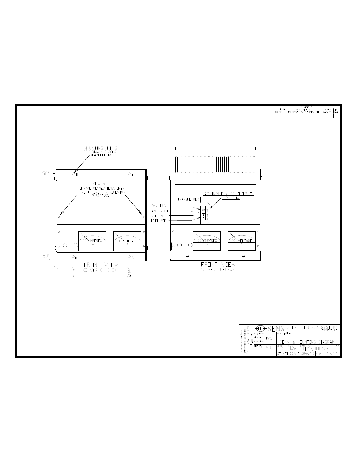
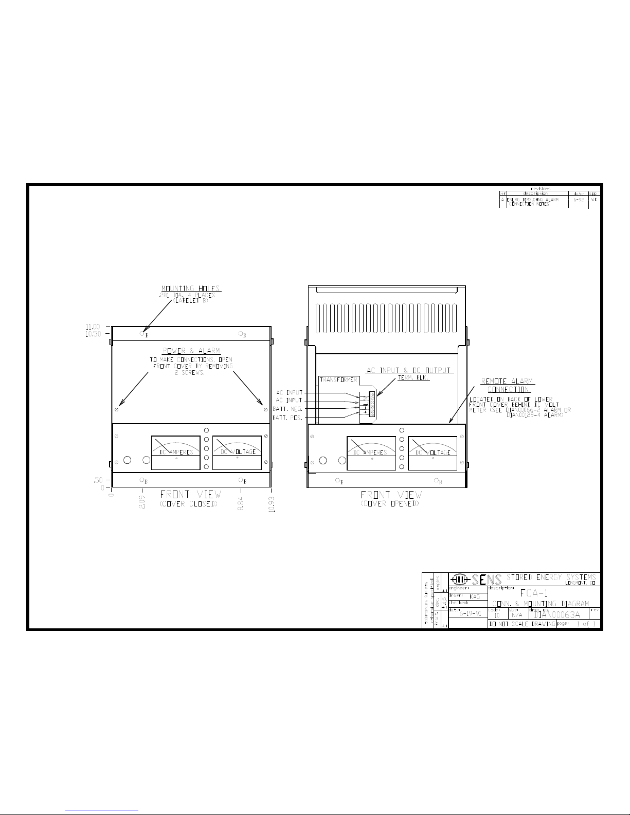
3.1 Mounting (for dimensions, refer to drawings at end of manual)
Mount on a clean, dry, fixed wall that is protected from extremes of temperature. Allow at least 6
inches above and below the unit, and 3 inches on either side for proper ventilation. The unit must be
mounted vertically.
If the charger must be mounted on or in a vibrating enclosure, the mounting arrangement should be
designed to provide full vibration isolation. Protect the charger from construction grit, metal
chips, paint or other debris. Clean away debris after installation.
3
Page 4
FC/FCA Charger Operation & Maintenance – 6 & 10 amp units
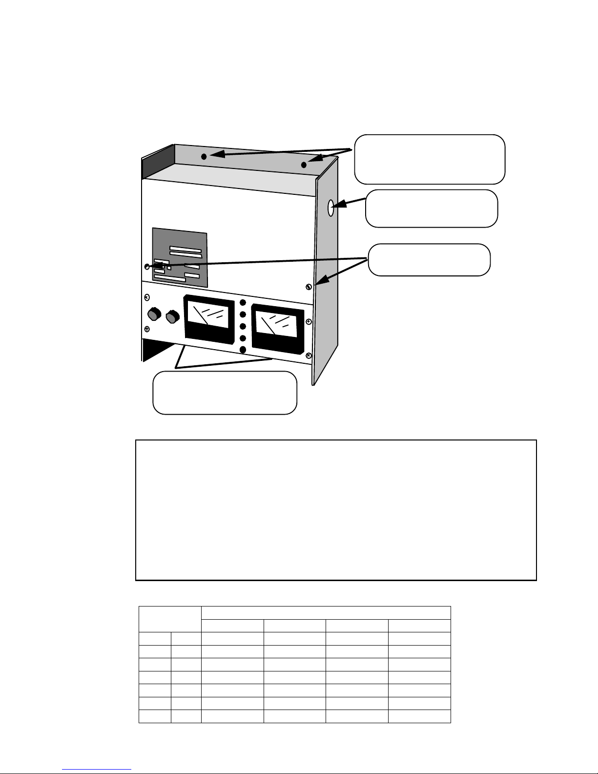
FIGURE 3.1
FC Charger Mounting (see diagram at end of document for dimensions)
9/32" holes to accommodate 1/4"
screws. Level charger on wall if
necessary with washers. Use washer,
locknut with each screw.
Knockout for 1/2" conduit and
fitting. One on each side.
Separate DC and AC wiring
Remove these screws to gain
access to terminal block
9/32" holes to accommodate 1/4"
screws. Level charger on wall if
necessary with washers
3.2 Power Connections
WARNING: FC/FCA chargers use different fusing configurations as follows:
115 & 277 volt, 60 Hz Single pole input fuse
220 volt, 60 Hz* 2-pole input fuses (to protect two live leads - there is no
neutral lead used)
220 volt, 50 Hz** Single pole input fuse
Ensure that you have the correct fusing configuration.
1. The neutral must NEVER be fused
2. The live conductors must be fused
* All 60 Hz voltages except 115 and 277 use this configuration
* All 50 Hz voltages use this configuration unless specially ordered
TABLE 3.2
Charger
Output
AC Input Current Ratings
AC Input Current
120 V i/p 208 V i/p 240 V i/p 480 V I/p
V A Amps Amps Amps Amps
12 6 3 1.0 0.9 0.4
12 10 3 1.6 1.4 0.7
24 6 4 2.0 1.7 0.9
24 10 6 3.3 2.9 1.4
32 6 4.6 2.6 2.3 1.1
32 10 7.6 4.4 3.8 1.9
4
Page 5

FC/FCA Charger Operation & Maintenance – 6 & 10 amp units
4
Using the
Charger
Refer to the drawings at the back of this guide. Connection should be made by a qualified installer.
Remove the two screws securing the charger's top front panel to gain access to the connections.
• Use AWG #12 or larger wire rated for 90C temperature or higher for DC (charger to battery)
leads.
• Use AWG #14 or larger wire rated for 90C temperatu re or higher for AC input and ground
connections
WARNING: The battery charger should be connected to a grounded permanent wiring system. A
ground stud is provided for this purpose
Knockouts accommodating 1/2" conduit and fittings are located on each side of the charger. Run
the AC wiring independent of the DC and alarm wiring.
The voltmeter will show battery voltage as soon as the DC connection is completed. Check the
voltmeter as soon as the FC connection has been made. If the meter reads zero or is deflecting
below zero, reverse the polarity of the battery connections. Do not energize the charger with the
battery connected backwards--the DC fuse will blow.
3.3 Alarm Connections (pertains only to FCA models)
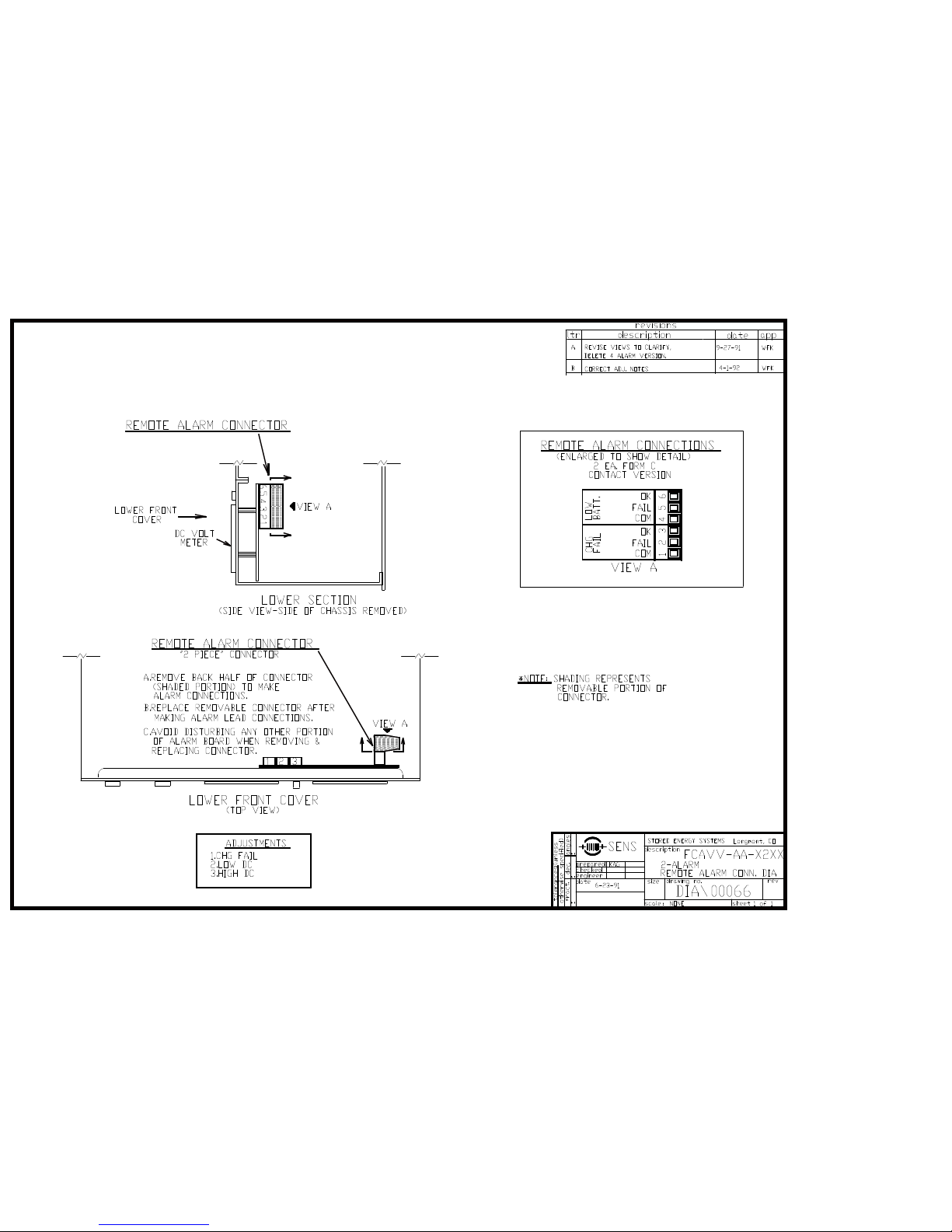
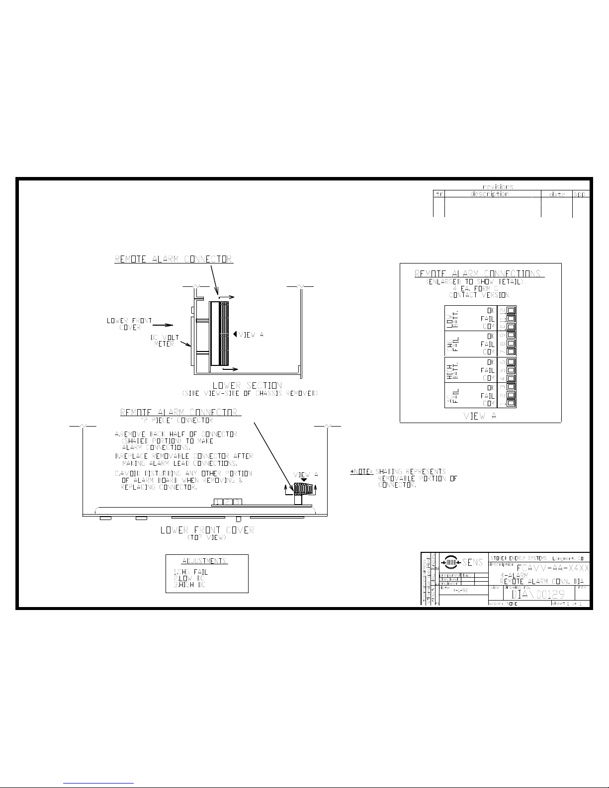
Caution: Connection to the alarms is somewhat delicate; complete instructions and detailed
drawings are provided at the end of this guide. Use stranded wire, rather than solid, if it is
available.
The alarm relays are rated for a maximum of 2 amps at 25 volts DC, or 0.5 amp at 120 volts AC
(non-inductive loads only). Connect the alarm relay to customer-supp lied supervisory system only
-- do not apply AC mains power to the relays and do not exceed the relays’ ratings.
Two versions of FCA alarm board are available:
Condition
AC on Green LED -2211, -2411
Low battery voltage Amber LED -2211, -2411
Charger failure Red LED -2211, -2411
AC fail Red LED -2411 only
High battery voltage Red LED -2411 only
4.1 Features of the Charger
FC/FCA chargers feature soft start circuitry which causes a gradual increase in output power after
application of AC power. The Autoboost system causes the charger initially to operate at the high
rate. When the charger reaches the boost voltage set point, and current has dropped to approximately
50% to 70% of the charger's rating, the charger will revert to the float mode. The transition from
boost to float will cause the output current of the charger to drop to zero amps until the battery
voltage drops to the float level. Once the battery voltage nears the float setting, the charger will
again deliver a small amount of current to the battery to maintain it at its fully charged state. Figure
3 is a graph of how the Autoboost system works.
NOTE: Autoboost is disabled on chargers shi p ped for use with sealed lead-acid batteries, per the
recommendation of most battery manufacturers.
The battery charger is temperature compensated to match the negative temperature coefficient of
the battery. Thus the float voltage will increase slightly as the temperature decreases, and decrease
as temperature increases. The battery charger is electronically current limited to 110% of rated
output. The charger will reduce its current output when the battery voltage is lower than normal so
LED Indicator FCA model suffix
5
Page 6
FC/FCA Charger Operation & Maintenance – 6 & 10 amp units
w
p
o
that the charger’s rated output power in watts is not exceeded. The charger uses True Voltage
Sensing (TVS) to automatically compensate for voltage drop in the charging leads. TVS senses
current flow between output current pulses, when current flow and voltage drop are zero. TVS
interacts with the battery and therefore a battery is required for correct operation of the charger.
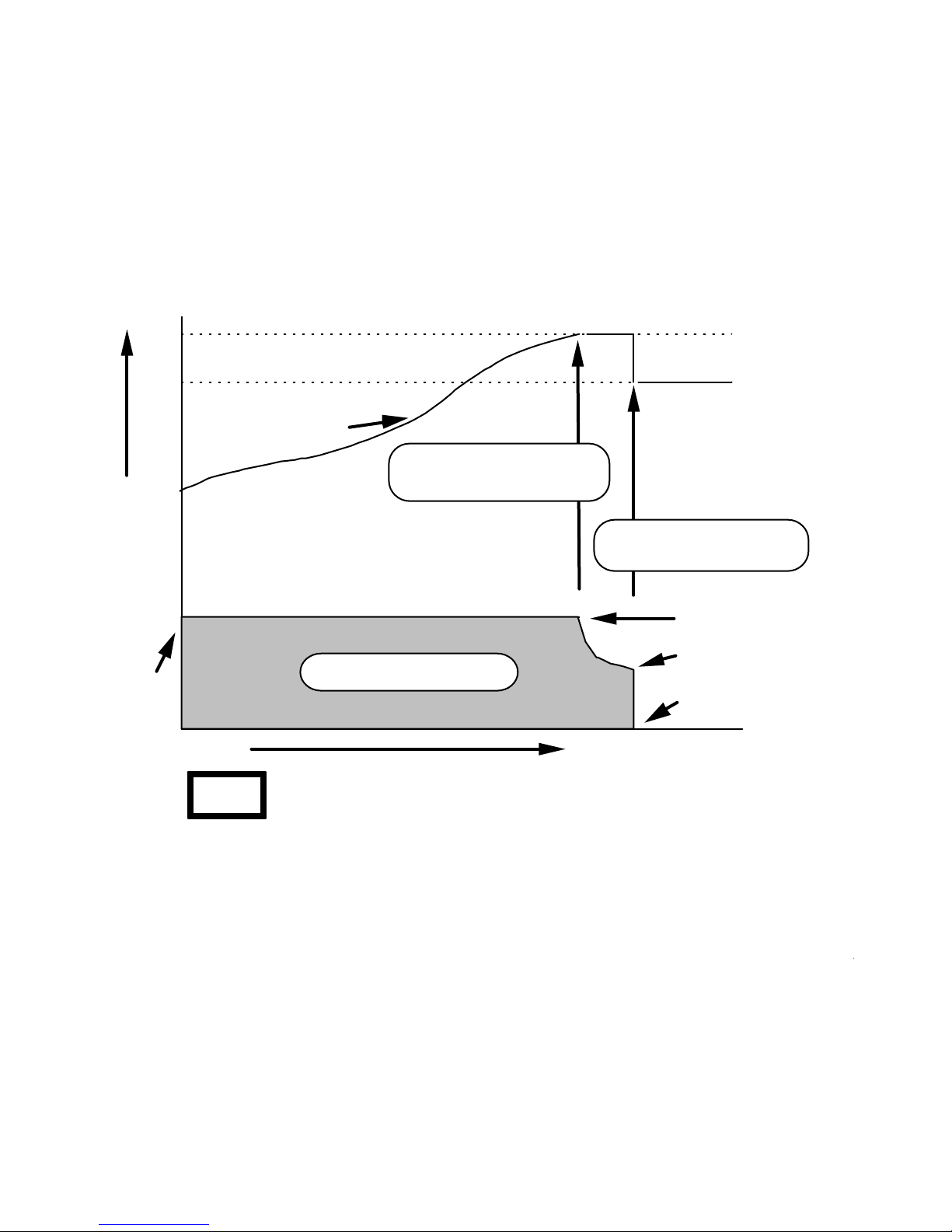
FIGURE 4.1
Boost voltage
Float voltage
Battery voltage
Point at which charger changes
Volts
from current limit to voltage limit
Point at which AUTOBOOST
returns charger to float voltage
100% charger
output current
50% to 75% of
charger current limit
Zero current flow
Amps
0
Time
NOTE:
Charger output current
When the charger switches from BOOST to FLOAT mode,
no current will flow into the battery for a while due to the battery's
high state of charge. This is completely normal, and indicates
that the charger is working properly.
4.2 Ammeter, Voltmeter and Charger Troubleshooting
The voltmeter and ammeter (and alarm LEDs on the FCA models) provide indication of normal
operation. Correct operation is indicated when the voltmeter reads 110% to 120% of nominal battery
voltage. High current flow indicates that the battery has been discharged, and is being recharged. Lo
current flow normally indicates that the battery is fully charged. The charger will at times read 0 am
This most commonly happens after the charger has reverted from the boost (or high rate) charge to fl
charge. Do not automatically assume that the charger has failed if the ammeter reads 0 amps!
4.3 Alarm Operation (pertains only to FCA models)
The alarm LEDs have the following meanings:
Power on: AC power is available to the charger
6
Page 7

FC/FCA Charger Operation & Maintenance – 6 & 10 amp units
Charge fail: The charger senses voltage rather than current to detect "failure";
once battery voltage drops approximately 1 volt below nominal the alarm activates.
This may occur when:
a) The battery is fully discharged
b) The AC power has failed, and the battery has become discharged
c) There is an excessive load on the charger (not a charger failure)
d) The charger has failed
There is a time delay of approximately one minute between the start of the alarm
condition and the actual alarm signal. This prevents spurious indications during
short-term deep battery discharge (as would happen during engine cranking).
AC fail There is no AC power to the charger. This indicates either:
a) The AC power has failed
b) The input fuse is blown
High battery: Indicates that the output voltage is above a preset, adjustable
point. The control circuit may have malfunctioned, or it could be misadjusted. In
some cases, long leads of small gauge wire to the batteries cause a high battery
alarm. The charger's True Voltage Sensing circuit automatically compensates for
voltage drop in the charging leads. If charging leads are too small, the charger will
operate at a high voltage to overcome high resistance in the leads. The alarm
indication is made as soon as the alarm condition begins and lasts for approximately
one minute after the alarm condition ends.
Low battery: Indication is made when the battery voltage is below a preset,
adjustable point. This may occur when:
a) The AC power has failed and the battery has become discharged
b) The charger has malfunctioned
c) The battery is defective
There is a delay of approximately one minute between the start of the alarm
condition and the alarm signal. This prevents false indications due to engine
cranking or other temporary deep battery discharge. The delay period can be
adjusted. Consult the factory.
The FCA's alarm system includes Form C contacts. The contacts change position whenever the
associated alarm is activated.
When de-energized, the Form C contacts are in the “Failed” position (Fail and Com are connected)
5
Adjustments
Customer service of the charger is recommended only if the technician is experienced in electrical
and electronic equipment. If a trained technician is not available, return the charger to the factory
for adjustment. Note that adjustment of factory-set voltages without factory authorization voids the
charger’s warranty.
5.1 Adjusting the Charger Output Voltage (refer to Figure 5)
NOTE: There are two ways to adjust the charger voltage. The first method requires only an
external precision voltmeter. The second method takes less time, but requires a 40 volt, 100,000
microfarad capacitor and an adjustable load.
7
Page 8

FC/FCA Charger Operation & Maintenance – 6 & 10 amp units
NOTE: The charger cannot be correctly adjusted without either a battery or the capacitor
mentioned above. This is because SENS’ True Voltage Sensing circuit senses battery voltage only
between charging current pulses.
All chargers (adjustment procedure where capacitor and & load bank are not available)
Connect an external precision voltmeter to the battery. Adjust the charger in small increments -- it
takes time for the battery to adjust to new charger settings, so be patient.
1. Open upper front panel to gain access to control circuit.
2. Remove protective paper dots from potentiometers R30 and R34 (also labeled FLOAT and
BOOST).
3. Turn boost voltage pot R34 fully counter-clockwise.
4. Adjust float pot R30 in small increments until the battery reaches the desired voltage. The
voltage is not stable until the current drops to about 1 to 2 amps. Do not consider the adjustment
final until charger current is this low!
5. Turn the boost pot R34 fully clockwise (maximum output voltage).
Now adjust the boost charge voltage as described below:
Different adjustment procedures are used for AUTOBOOST and timed boost chargers.
AUTOBOOST chargers only (not equipped with a timer)
6. Put the charger in the AUTOBOOST mode by partially discharging the battery, then removing
and restoring the charger's AC power source.
7. Allow the battery voltage to rise to the desired high rate charge level. Once at this voltage,
carefully turn the boost pot counter-clockwise until the charger ammeter suddenly drops to
approximately zero amps.
8. Charger is now adjusted. Replace paper dots and close front cover.
Chargers with timed boost
6. Turn timer knob to start high rate charging.
7. Allow the battery voltage to rise to the desired high rate charge level. The battery should be
discharged so that charger is producing between 60% and 100% of its rated current. Once at the
desired boost voltage, carefully turn the boost pot counter-clockwise until the charger ammeter
drops noticeably (to between 1/2 and 2 amps).
8. Charger is now adjusted. Replace paper dots and close front cover.
Alternative adjustment procedure using capacitor and load bank -- all chargers
The capacitor and adjustable load take the place of a battery, so you do not have to wait for the
battery voltage to increase or decrease to new output voltage levels. The time delays in the alarm
circuit, however, cannot be defeated.
Connect the capacitor in parallel with the output terminals, making sure that the polarity is correct.
Use the same general adjustment procedure as the "all chargers" section above; setting chang e s,
however, do not have to be made in small increments. For the float adjustment, adjust the load
bank so that the charger puts out about one amp. For the boost adjustment, adjust the load bank so
that the charger puts out about 80% of its rated current. This high load causes AUTOBOOST
chargers to switch to high rate charge.
FIGURE 5
8
Page 9
FC/FCA Charger Operation & Maintenance – 6 & 10 amp units
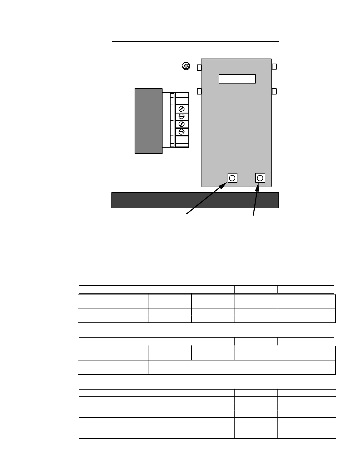
Control Board
Float adjustment pot
View of FC charger with upper and lower doors open
Boost adjustment pot
5.2 Factory-Set Output Voltages
Chargers set for liquid-electrolyte lead-acid battery
12 volt 24 volt 32 volt 48 volt
Float voltage 13.3 26.6 35.5 53.28
Boost voltage 14.0 28.0 37.3 56.00
Chargers set for sealed lead-acid battery
12 volt 24 volt 32 volt 48 volt
Float voltage 13.5 27.0 36.0 54.24
Boost voltage Boos t should be turned all the way off for sealed battery
Chargers set for nickel cadmium battery
12 volt 24 volt 32 volt 48 volt
Float (# cells), voltage (10) 14.3 (19) 27.2 (25) 35.8 (37) 52.91
(20) 28.6 (27) 38.6 (38) 54.34
Boost (# cells), voltage (10) 15.2 (19) 28.8 (25) 38.0 (37) 56.2
(20) 30.4 (27) 41.5 (38) 57.8
9
Page 10

FC/FCA Charger Operation & Maintenance – 6 & 10 amp units
5.3 Adjusting Alarm Voltage Levels
Three alarm adjustments are possible: charger failure alarm, low battery voltage alarm and high battery
voltage alarm. The location of the adjustment potentiometers is shown in drawing no DIA\00066 at the
end of this guide. Use an external precision voltmeter connected directly to the charger's output terminals.
To adjust the alarms, use an external adjustable DC power supply capable of providing up to 1/2 of an amp
and an infinitely variable range of 10 to 50 volts.
De-energize the charger, disconnect the battery and connect the power supply's output leads to the
charger's FC output terminals, being careful to observe correct polarity. Turn on the power supply. Verify
on the external meter that polarity is correct.
Low battery alarm: Adjust the power supply to the desired alarm level. Turn the alarm pot counter-
clockwise one revolution or so to increase the alarm voltage point. Wait until the
alarm activates (about one minute). Now slowly turn the adjustment pot clockwise
until the alarm light shuts off. This will be the voltage at which the adjustable power
supply is set.
Charge fail alarm: Set this alarm using the same procedure as the low battery voltage alarm.
High battery alarm: Adjust the power supply to the desired level. Turn the alarm pot counter-
clockwise one turn or so to reduce the alarm voltage to a low value. Now slowly
turn the adjustment pot clockwise until the alarm light turns on. This will be the
voltage at which the adjustable supply is set.
Chargers set for nickel cadmium battery
6
Troubleshooting Guide
(FC or FCA
chargers)
5.4 Factory-Set Alarm Voltages
Chargers set for lead-acid battery
12 volt 24 volt 32 volt 48 volt
Low battery alarm voltage
High battery alarm voltage
Charge fail alarm voltage
11.0 22.0 30.0 44.0
16.0 32.0 40.5 60.0
12.0 25.0 34.0 50.0
12 volt 24 volt 32 volt 48 volt
(# cells), low battery alarm voltage
(# cells), high battery alarm voltage
(# cells), charge fail alarm voltage
(10) 11.9
(10) 16.27
(10) 13.7
6.1 SENS’ Field Assistance Policy
SENS' policy is to help field technicians correct problems as fast and inexpensively as possible. We
encourage you to telephone SENS on our toll-free line for help--it will save you time and trouble.
6.2 Troubleshooting Table
10
(19) 22.61
(20) 23.8
(19) 30.9
(20) 32.6
(19) 26.0
(20) 27.4
25) 29.75
(27) 32.13
(25) 40.8
(27) 44.0
(25) 34.3
(27) 37.0
(37) 44.03
(38) 45.22
(37) 60.3
(38) 61.9
(37) 50.7
(38) 52.1
Page 11

FC/FCA Charger Operation & Maintenance – 6 & 10 amp units
Symptom Possible cause Test Repair procedure
No output AC or DC fuse blown
Battery not connected
No AC power
Ammeter disconnected
TB-3 disconnected
Defective control circuit
Defective transformer
AC fuse blows Wrong input voltage
Defective control circuit
DC fuse blows Defective control circuit
Battery leads reversed
Overcharging Improper boost/float settings
Defective control circuit
Undercharging Improper boost/float settings
Defective control circuit
Alarm Indications (FCA units only)
Indication Possible cause Test Repair procedure
AC fail AC fuse blown
No AC power
Defective alarm circuit
Charge fail AC or DC fuse blown
No AC power
Excessive load
Battery voltage low
Defective alarm circuit
High DC Improper voltage settings
Defective control circuit
Defective alarm circuit
Low DC AC fuse blown
DC fuse blown
No AC power
Excessive load
Defective alarm circuit
#1
#2
#3
#4
#4
#1
#1
#5
#4
#1
#1
#5
Replace fuse
Connect battery
Restore AC
Reconnect
Reconnect
Call SENS for assistance
Call SENS for assistance
Connect to correct voltage
Call SENS for assistance
Call SENS for assistance
Call SENS for assistance
Adjust output voltages
Call SENS for assistance
Adjust output voltages
Call SENS for assistance
Replace AC fuse
Restore AC
Call SENS for assistance
Replace fuse
Restore AC
Reduce load
Dead battery
Call SENS for assistance
Adjust output/alarm volt ages
Call SENS for assistance
Call SENS for assistance
Replace AC fuse
Replace DC fuse
Restore AC
Reduce load
Call SENS for assistance
11
Page 12
FC/FCA Charger Operation & Maintenance – 6 & 10 amp units
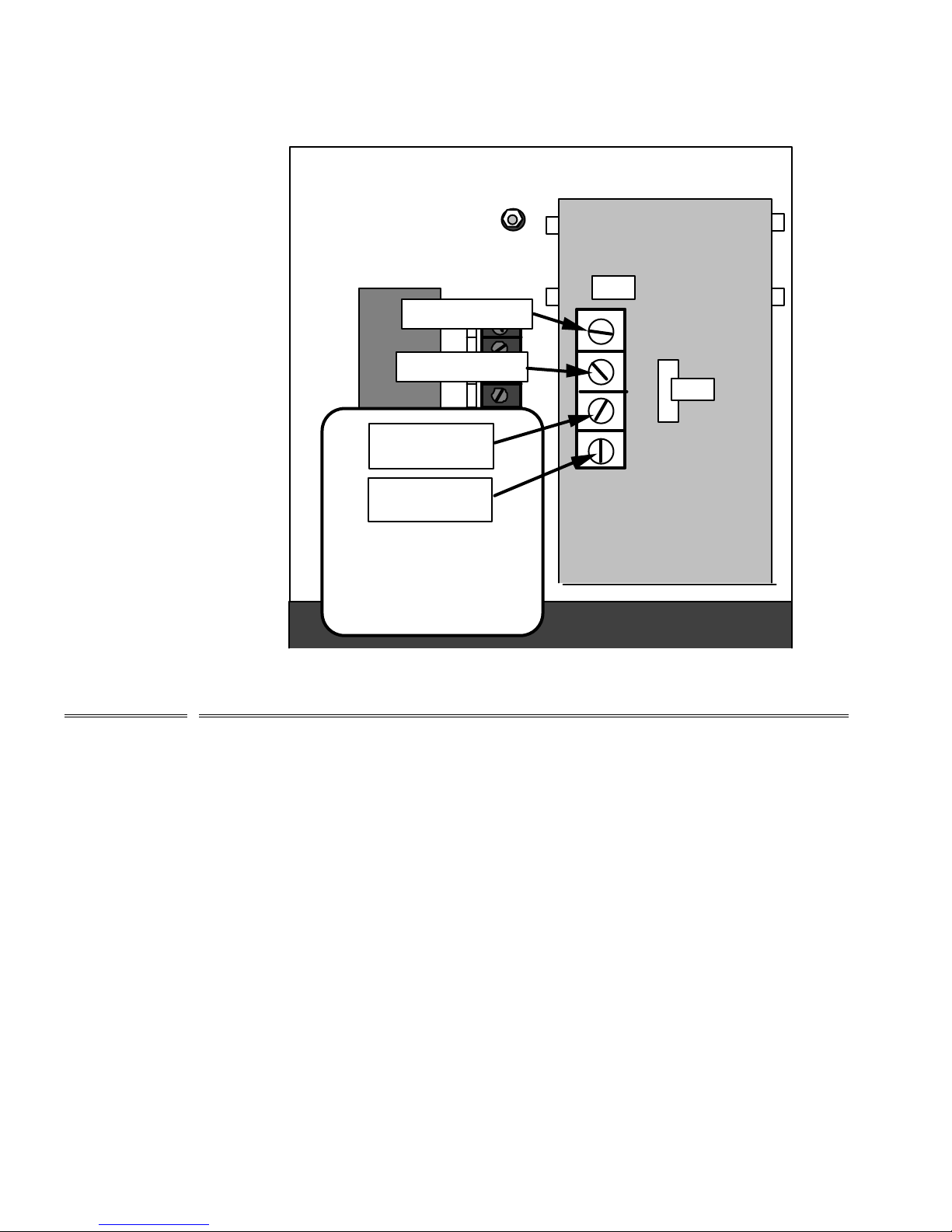
FIGURE 6
Brown wire (-) DC
Red wire (+) DC
Orange striped
wire (AC)
Solid orange
wire (AC)
TB-1
TB-3
7
Test Procedures
Transformer secondary leads
NOTE:
Leads must be reconnected exactly as
shown
Test #1: Remove the fuse and measure its resistance using an ohmmeter on the Rx1 range. Meter
should read 0 ohms for a good fuse.
Test #2: Energize the charger after disconnecting the secondary leads from the control board and
measure the secondary voltage. Do not short circuit the leads while performing this test. The AC
voltage should be 1.5 to 2 times the nominal output voltage of the charger. The control winding
(TB3A) should be approximately 10-14 volts AC rms. See Figure 6 for location of leads.
Test #3: Check the information on the nameplate to ensure it agrees with the AC voltage applied.
Test #4: Measure the battery voltage using a 1% accuracy voltmeter. If the charger's voltage is not set
properly for your batteries, adjust float/boost settings according to the adjustment procedure.
Test #5: Loads greater than the charger's rating will cause the control circuit to reduce output voltage
so that the total output power in does not exceed the charger’s rating. This is normal with a dead or
deeply discharged battery.
12
Page 13
Page 14
Page 15
Page 16
Page 17

SENS Limited Warranty Policy
What is covered:
This warranty covers any defect in material and workmanship on battery chargers manufactured
by Stored Energy Systems, a Colorado Limited
Liability Company (SENS).
What this warranty does not cover:
This warranty does not cover damages, defects or failures of your equipment resulting from
shipping damage, accidents, installation errors, unauthorized adjustment or repair, unauthorized
third-party service, failure to follow instructions, misuse, fire, flood, acts of persons not in our
control, and acts of God.
For how long:
Two years from date of shipment.
What we will do:
If your battery charger is defective within two years of date of shipment, we will repair it or, at
our option, replace it at no charge to you.
If we choose to replace your charger, we may replace it with a new or refurbished one of the
same or similar design. The repair or replacement will be warranted for the remainder of the
original two-year warranty period. If we determine that your charger cannot be repaired or
replaced, we will refund its purchase price to you.
What we ask you to do:
First contact SENS service department to obtain warranty service instructions. To obtain
warranty service the product must be returned, freight prepaid, to the factory under a Return
Merchandise Authorization (RMA) number provided by SENS. If, in SENS’ opinion, the
problem can be rectified in the field, SENS may elect to ship replacement parts for customer
installation instead of having the product returned to the factory.
Limitation:
This warranty is limited to defects in material or workmanship of the product. It does not cover
loss of time, inconvenience, property damage or any consequential damages. Repair,
replacement or refund of the purchase price of the equipment is your exclusive remedy.
Form.135-1
 Loading...