

Page 1
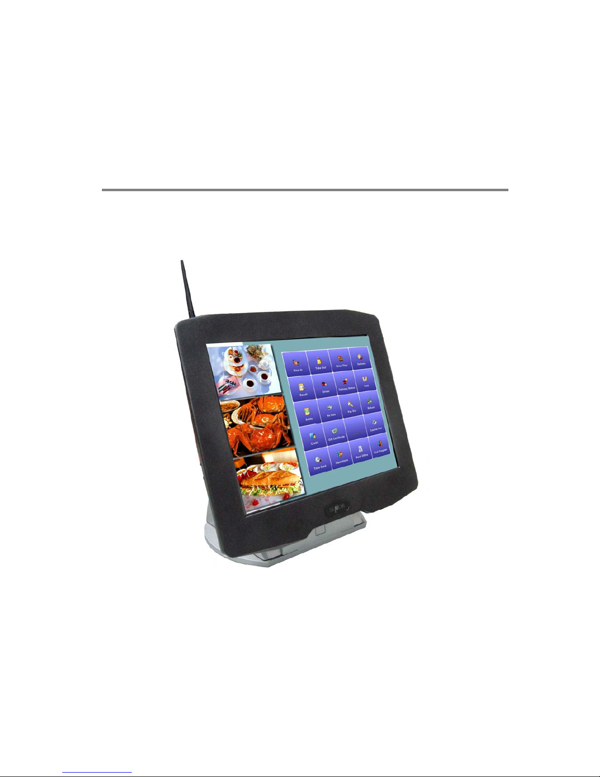
iSPOS
User’s Manual
SENOR TECH CO., LTD
http://www.senortech.com
Page 2

SENOR TECH CO., LTD.
iSPOS User’s manual
2
SAFETY STATEMENTS
Product Name : iSPOS
The following standards are applied only to the equipments that are
so labeled.
Europe : CE marking, TUV/GS : EN60950-1
North America : EMI : FCC Class B
National : IEC 60950-1
CE Marking
The equipment conforms to the following Directive and Norms.
EMC Directive 89/336/EEC - EN55022 Class
B;EN55024;EN61000-3-2;EN61000-3-3.
Low Voltage Directive 73/23/EEC – Safety:EN60950-1.
Federal Communications Commission statement
This equipment has been tested and found to comply with the limits
for a class B digital device, pursuant to Part 15 of the FCC rules.
These limits are designed to provide reasonable protection against
harmful interference in a residential installation. This equipment
generates, uses, and can radiate radio frequency energy and, if not
installed and used in accordance with the instructions, may cause
harmful interference to radio communications. However, there is no
guarantee that interference will not occur in a particular installation. If
this equipment does cause harmful interference to radio or television
reception, which can be determined by turning the equipment off and
on, the user is encouraged to try to correct the interference by one or
more of the following measures:
z Reorient or relocate the receiving antenna.
z Increase the separation between the equipment and receiver.
z Connect the equipment into an outlet on a circuit different from
that to which the receiver is connected.
Page 3

SENOR TECH CO., LTD.
iSPOS User’s manual
3
z Consult the dealer or an experienced radio/TV technician for help.
FCC Radiation Exposure Statement
This statement complies with FCC RF radiation exposure limits set
forth for an uncontrolled environment.
This device complies with Part 15 FCC RF rules. Operation is
subject to the following two conditions:
1) this device may not cause interference and
2) this device must accept any interference, including interference
that may cause undesired operation of the device.
FCC RF Spec.
Interface
Mini PCI
Network Standard
IEEE802.11b/g
Modulation
802.11b----CCK (11Mbps. 5.5Mbps), QPSK (2Mbps), BPSK
802.11g----OFDM
Technique
Direct Sequence Spread Spectrum
Operating Frequency
2.412 ~ 2.462 GHz: North America
2.412 ~ 2.472 GHz: Europe (ETSI)
Operating Channels
1 ~ 11 for North America
1 ~ 13 for Europe (ETSI)
RF Output Power
11b:18dBm +/- 1dBm(peak)
11g: 20dBm +/- 1dBm(peak)
Antenna
Dipole antenna.
Supply Voltage
3.3V
Page 4

SENOR TECH CO., LTD.
iSPOS User’s manual
4
TRADEMARKS and ACKNOWLEDGEMENTS
All brand names and trademarks used in this manual are the properties and
registered brands of their respective owners
TABLE OF CONTENTS
1. SPECIFICATION...………………………………………….
2. TERMINAL OVERVIEW AND OPERATION…………….
2.1 LCD Angle Adjust..…………………………………..
2.2 Touch Screen…………………………………………
2.3 Removable Hard Disk Drive..………………………
2.4 Connectors……………………………………………
2.5 Power on……………………………………………….
2.6 CF Card Installation and Removal….....………….
2.7 Wireless LAN Card Installation.…………..…….....
2.8 Modem Card Installation…………………………....
2.9 Cashdrawer Board Installation...……………….....
3. INSTALLATION……………………………...……………..
3.1 Pre-installation………………………………...……..
3.2 Mounting……......……………………………………..
4. REGULAR MAINTENANCE..……………..……...……….
4.1 Cleaning………………………………………………..
4.2 Touch Screen…....……………………………………
5. TROUBLESHOOTING……...……………..……………….
5.1 General Troubleshooting…………………………...
5.2 LCD Troubleshooting…..……………………..….…
5.3 Disk Driver Troubleshooting…….…………………
5.4 RAM Troubleshooting…….…………………………
5.5 Serial Port Troubleshooting……..…………………
5.6 Error Messages………….…………………………...
CAUTION............................................................................
PRECAUTION………………………………………………….
5
9
11
11
12
14
16
17
18
19
20
20
20
21
25
25
25
26
26
26
27
27
27
28
29
30
Page 5
SENOR TECH CO., LTD.
iSPOS User’s manual
5
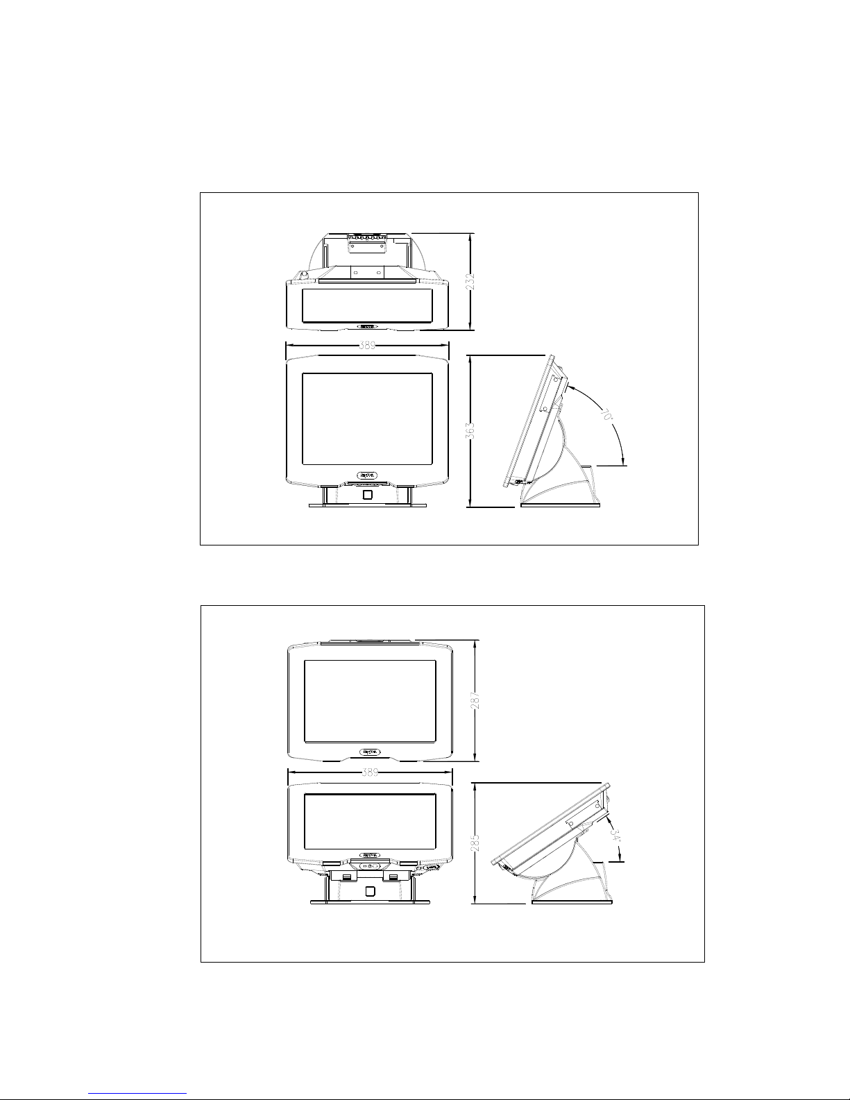
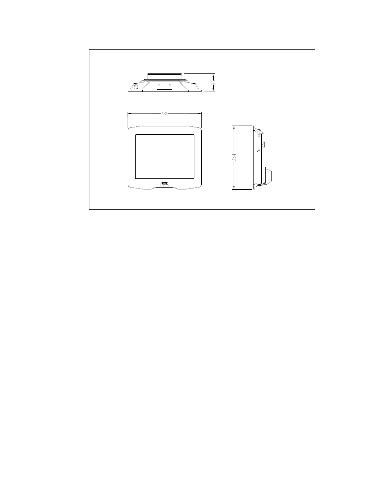
1. SPECIFICATION
Overall Dimensions
iSPOS
iSPOS
Page 6
SENOR TECH CO., LTD.
iSPOS User’s manual
6
iSPOS
Weight:
8.5 Kg
EMC:
CE、FCC Compliant、CCC
Safety:
UL、CE、TUV
CPU:
Micro-FCPGA AMD LX800
System Chipset:
AMD LX + CS5536 Chipset:
BIOS:
Award BIOS, 2M Support ACPI Function
Standard I/O:
1 × PS/2 Port (Keyboard)
4 × USB 2.0 Port (3 External USB 2.0 Port, 1 Internal USB 2.0 Port)
Page 7

SENOR TECH CO., LTD.
iSPOS User’s manual
7
1 × Mini Printer Port
1 × LAN Port
1 × Audio Port
1 × MIC Port
1 x Compact Flash type II socket for CF card
4 × RJ-48 Com Port (COM3 ~ 6)
System Memory:
One DDR SODIMM, support up to 1GB DDR 333/400 SDRAM
Ethernet:
REALTEK RTL8100(10/100) / 8110SC (10/100)
Ethernet Controller Supports wake up-on-LAN function
VGA:
AMD LX built-in
Microsoft Windows GDI GUI Acceleration.
Audio Interface:
Codec ALC203
USB Interface:
CS5536 built-in USB 2.0 host controller supports 4 ports
Hard Disk Drive
2.5" Removable HDD 33/66/100
Operator Display
Size 15” (diagonal)
Active Area 304.1 mm (H) x 228.1 mm (V)
Resolution 1024 (H) x 768 (V) x R,G,B
Display Mode Normally White
Contrast Ratio 500:1 type.
Luminance 250 cd/m² type.
Page 8

SENOR TECH CO., LTD.
iSPOS User’s manual
8
Touch Screen
Technology 5 Wire analogue resistive
Chemically strengthened backing
glass.
Resolution 4096 x 4096 points
Activation Force 5.5g
Linearity 62.0%
Transparency 75%
Surface Hardness 2H
Interface RS-232 Serial
MTBF 1,000,000 touches / spot
Power Supply
Input Voltage 100 ~ 240Vac
Input Frequency 47 ~ 63Hz
Input Current 100-240Vac 1.5A
Output Voltage +12Vdc 5A
Operating temperature 0°C to 40°C
Size 120mm(L) x 60mm(W) x 38mm(H)
Enclosure Water & Dust Protection (IP Rating)
iSPOS conforms to IP 65.
Note: Specifications are subject to change without notice.
Page 9
SENOR TECH CO., LTD.
iSPOS User’s manual
9
2. TERMINAL OVERVIEW AND OPERATION
The iSPOS is a Point Of Sale / Information terminal with all major functions
housed in one single unit.
Features :
15” LCD Operator Display with Manual Tilt Mechanism
Touch Screen
20 character x 2 line VFD Customer Display (option)
Removable Hard Disk Drive
6 x Serial Ports (4 External Serial Port and 2 Internal for Touch and VFD)
1 x Network Port
4 x USB 2.0 Ports (3 External USB 2.0 Port and 1 Internal for Finger print)
Audio Output
MIC port
Easy Installation
Easy Maintenance
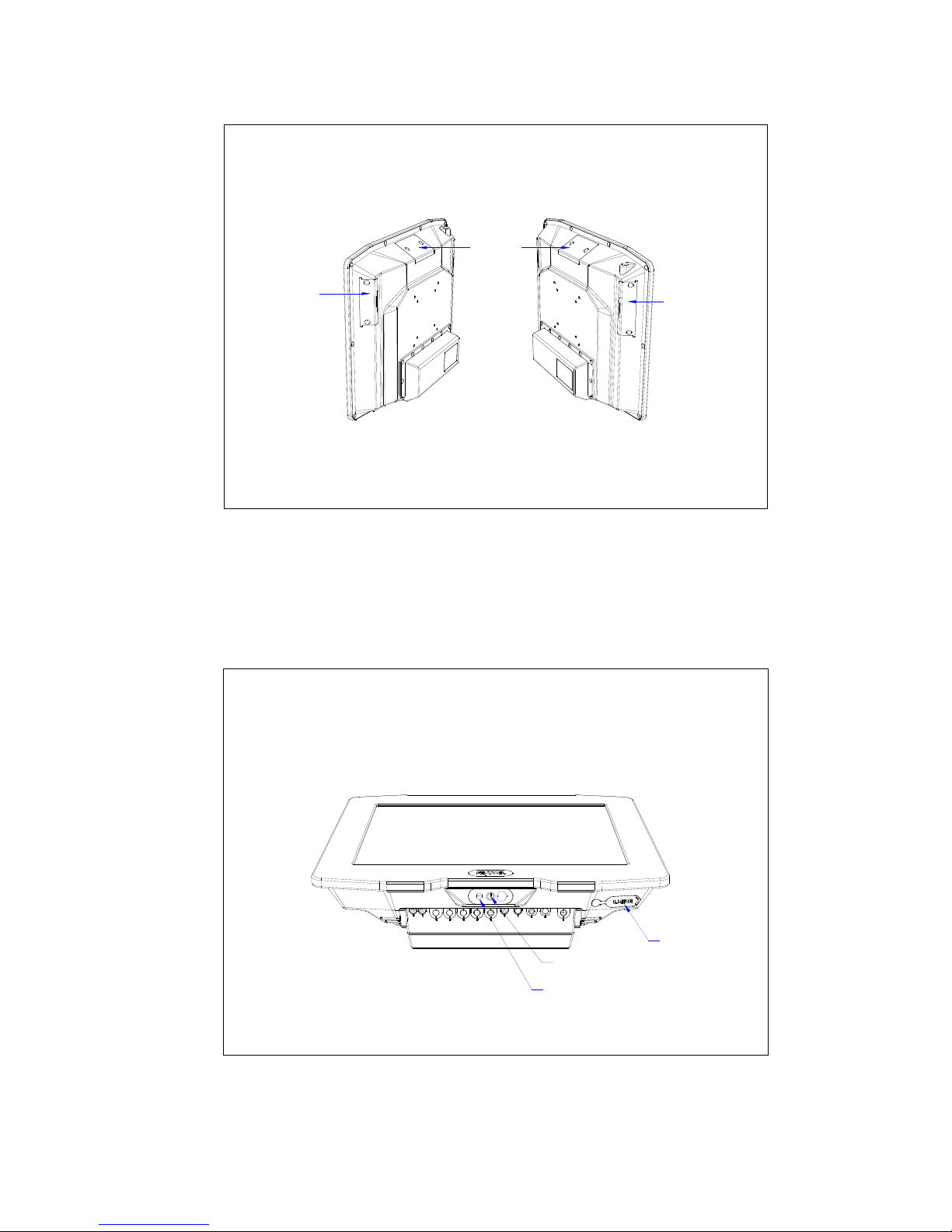
Overview – iSPOS
iSPOS
VFD
(Option)
Removable
Hard Disk Drive
Reader
(Option)
Page 10
SENOR TECH CO., LTD.
iSPOS User’s manual
10
iSPOS
VFD
(Option)
(Option)
Reader
Removable
Hard Disk Drive
Push ON Switch
Ext USB
HDD LED
Page 11
SENOR TECH CO., LTD.
iSPOS User’s manual
11
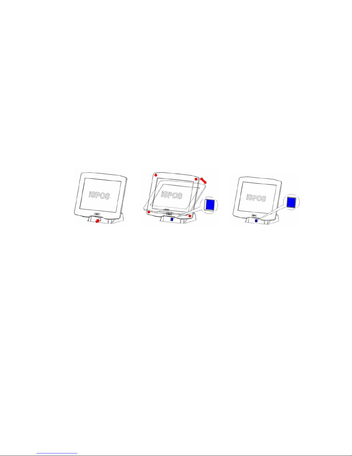
2.1 LCD Angle Adjust
1. In order to accommodate various operator preferences and lighting
conditions. iSPOS is equipped with a manual tilt adjustment mechanism.
The Adjustment button is located underneath the operator display.
Refer to diagram (1).
2. To adjust the tilt angle, press adjustment button as indicate direction.
Pressing and holding the button in enables tilt adjustment. The tilt
movement is limited to a minimum of 34 degree and a maximum to 70
degrees. Refer to Diagram (2)
3. After tilt angle has been adjusted, release the button. When adjustment
button released the LCD angle is locked.
2.2 Touch Screen
The touch screen uses a 5 wire analog resistive technology, mounted on a
chemically strengthened backing glass, with a resolution of 4096 x 4096
touch points. The iSPOS is designed so that the application accepts all
user input via the touch screen. Drivers are provided which allow the touch
screen to emulate mouse operation; therefore most mouse driven
applications will accept input from the touch screen.
Diagram (1) Diagram (2) Diagram (3)
Page 12
SENOR TECH CO., LTD.
iSPOS User’s manual
12
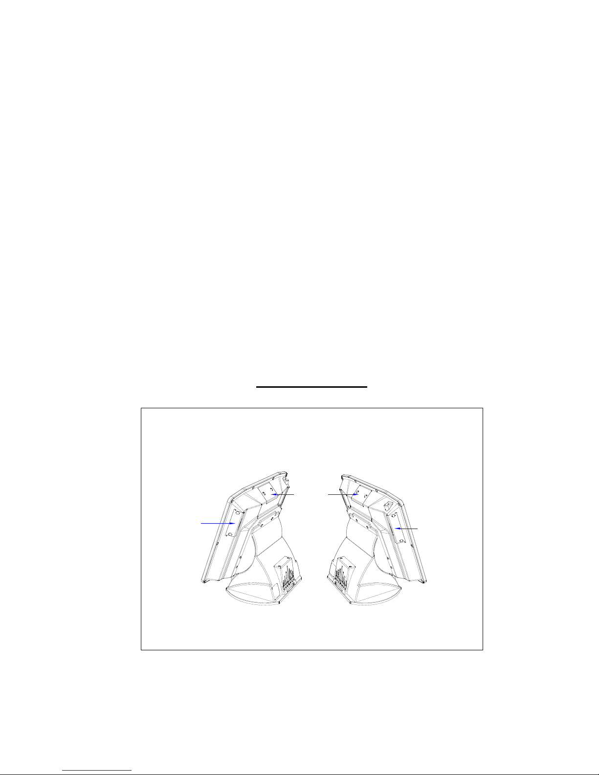
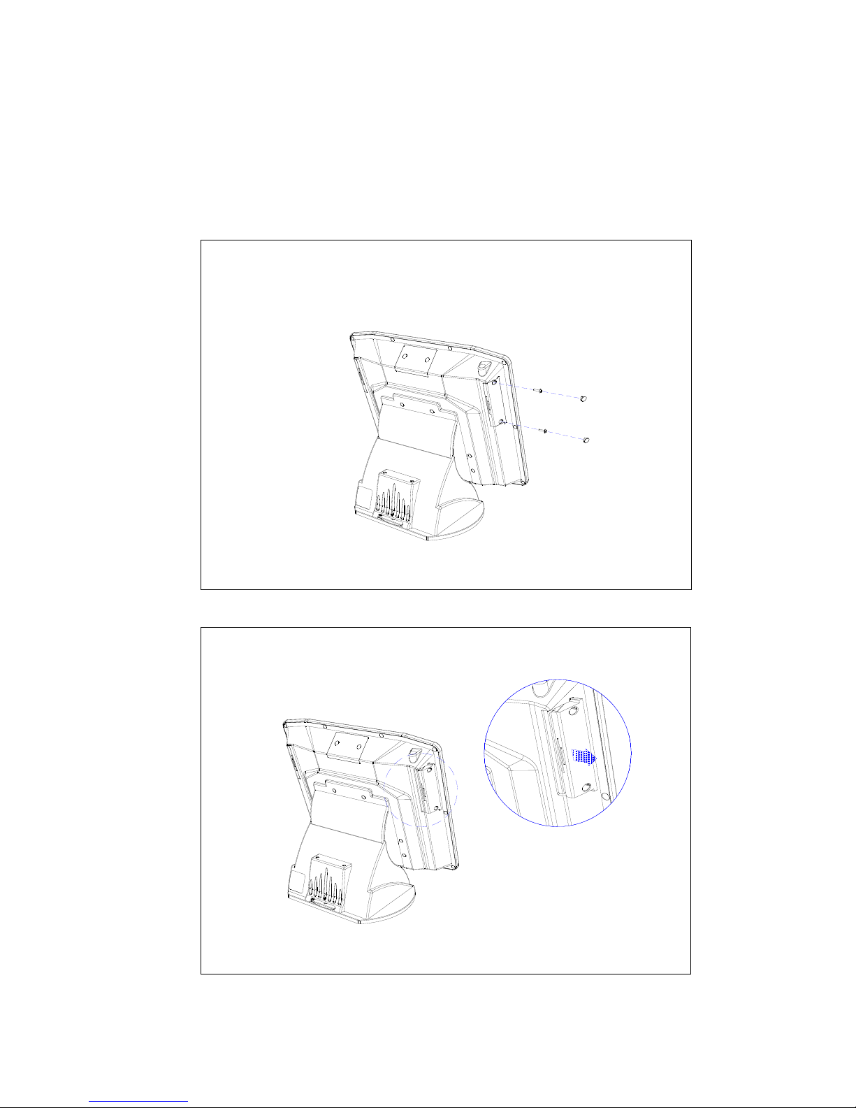
2.3 Removable Hard Disk Drive
The removable hard disk is located left side of panel. The following
drawings illustrate removal procedure.
Page 13
SENOR TECH CO., LTD.
iSPOS User’s manual
13
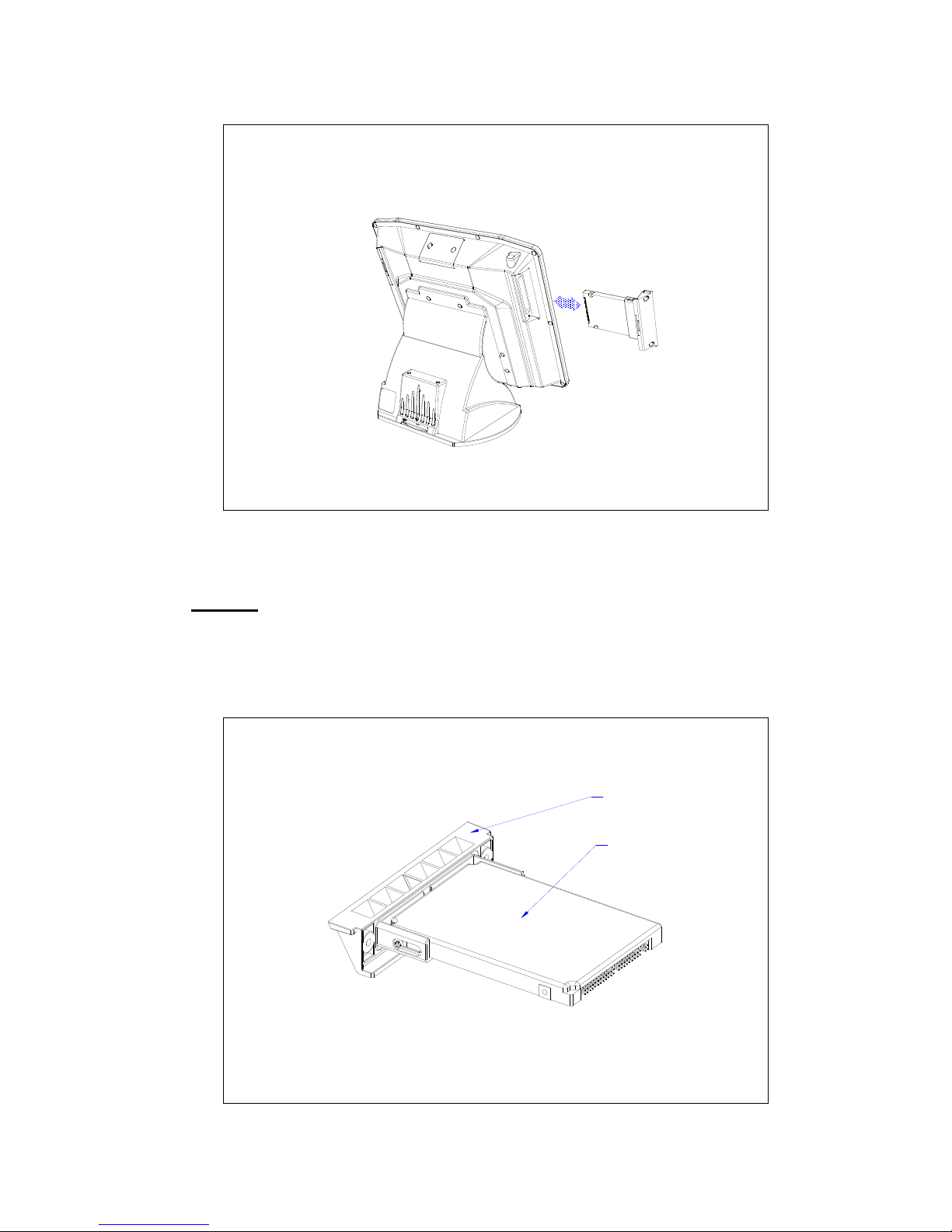
Caution:
A. The HDD must be fitted with HDD door.
B. Do Not
insert the HDD into the iSPOS without the HDD Door installed
or damage to the HDD and/or the iSPOS will occur.
C. The iSPOS power must be switched off before inserting or removing
the HDD
HDD
HDD Door
Page 14
SENOR TECH CO., LTD.
iSPOS User’s manual
14
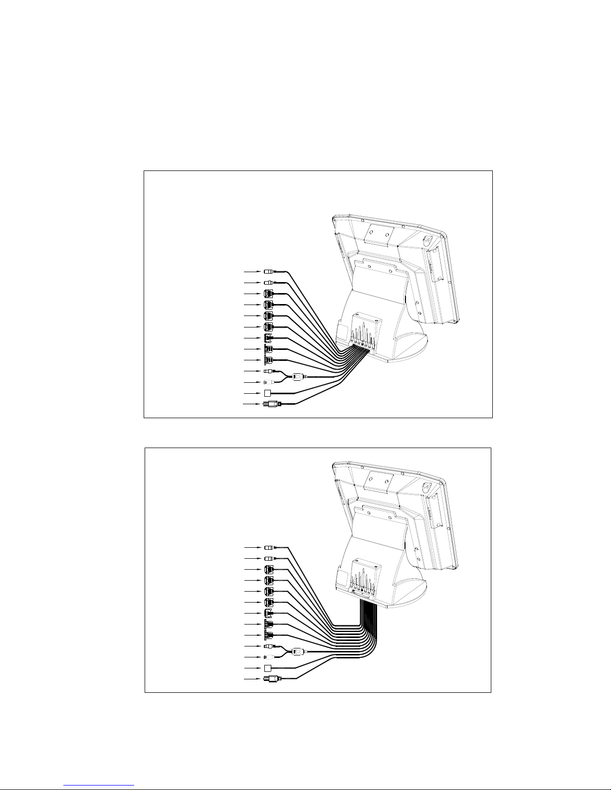
2.4 Connectors
All connections are located underneath the unit.
TYPE A – I/O Cable exit from back of Base.
LAN
USB
USB
COM3
COM4
COM5
Audio
COM6
Mic In
I/O Cables x 12
MINI PRINT
AC POWER CABLE
TYPE A
PS2 K/B
PS2 Loop IR K/B
iSPOS
TYPE B – I/O Cable exit from underneath the Base.
COM6
Audio
COM5
COM4
COM3
USB
USB
I/O Cables x 12
PS2 Loop IR K/B
PS2 K/B
AC POWER CABLE
MINI PRINT
TYPE B
iSPOS
Mic In
LAN
Page 15
SENOR TECH CO., LTD.
iSPOS User’s manual
15
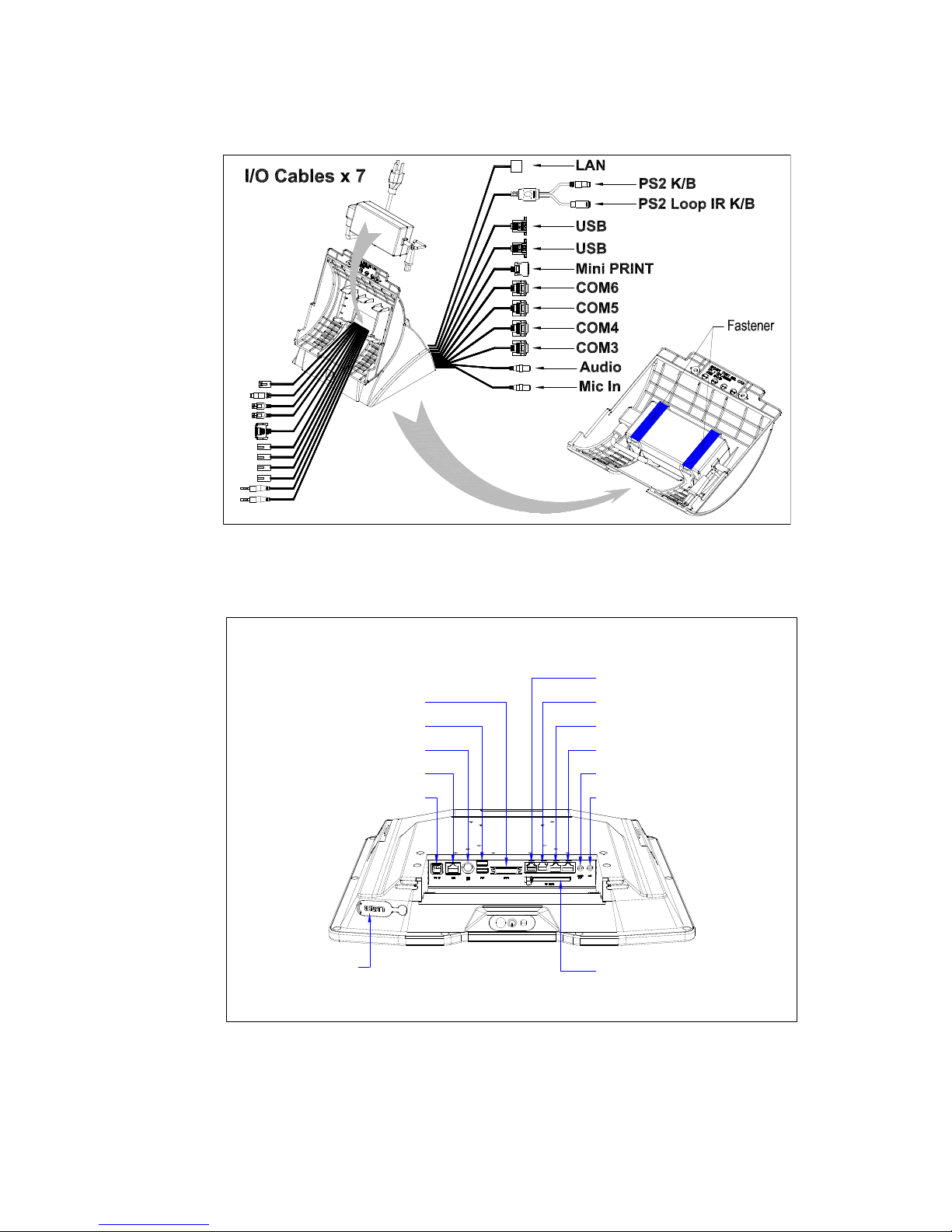
Base and I/O Cable inner view.
Connector locations
EXT USB
iSPOS
CF Card
EXT USB
Mini Printer
PS2 K/B
DC Power
LAN
COM6
COM5
COM4
COM3
Audio Out
MIC
Page 16
SENOR TECH CO., LTD.
iSPOS User’s manual
16
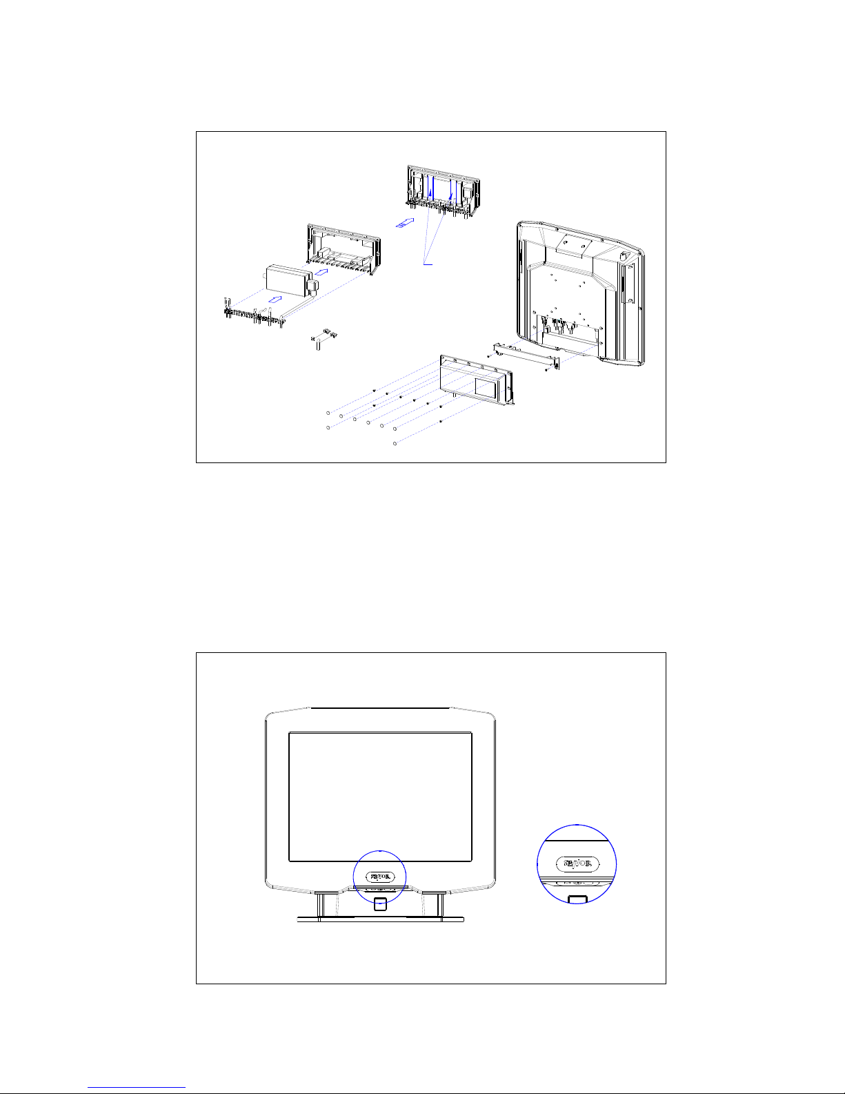
Power Supply Enclosure
iSPOS
Fastener
2.5 Power on
Turn on the unit by pressing the “Push ON Switch” located under the
SENOR Logo on the front of LCD, turn off the unit by pressing and holding
the switch for 3 seconds.When connected to an AC source, the Power
Mode LED will illuminate automatically. The unit’s mode can be
determined by the Power Mode LED color.
Red-------- AC Input OK
Blue------- Booting Mode
Page 17
SENOR TECH CO., LTD.
iSPOS User’s manual
17
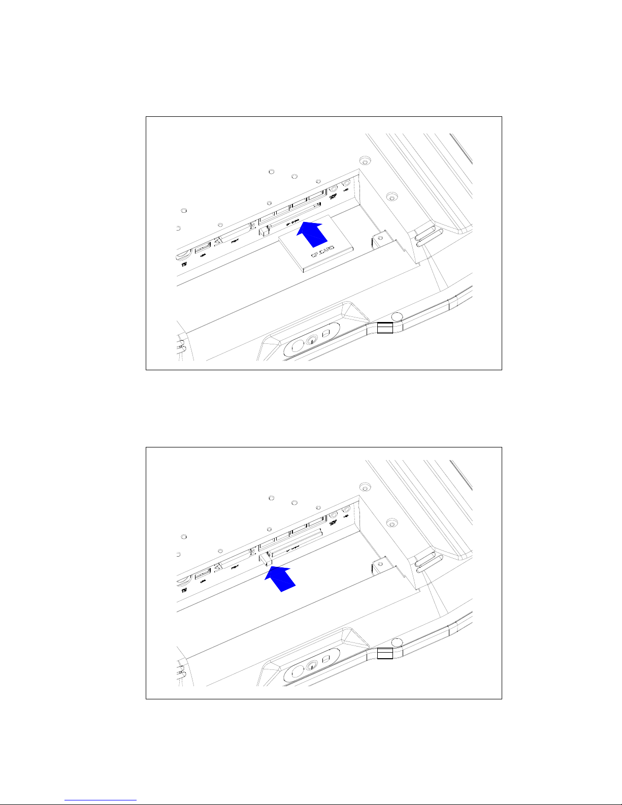
2.6 CF Card Installation and Removal
2.6.1 Insert CF card as diagram (1).
Diagram (1) : CF card installation
2.6.2 Remove the CF card by pressing black button as indicated.
Page 18
SENOR TECH CO., LTD.
iSPOS User’s manual
18
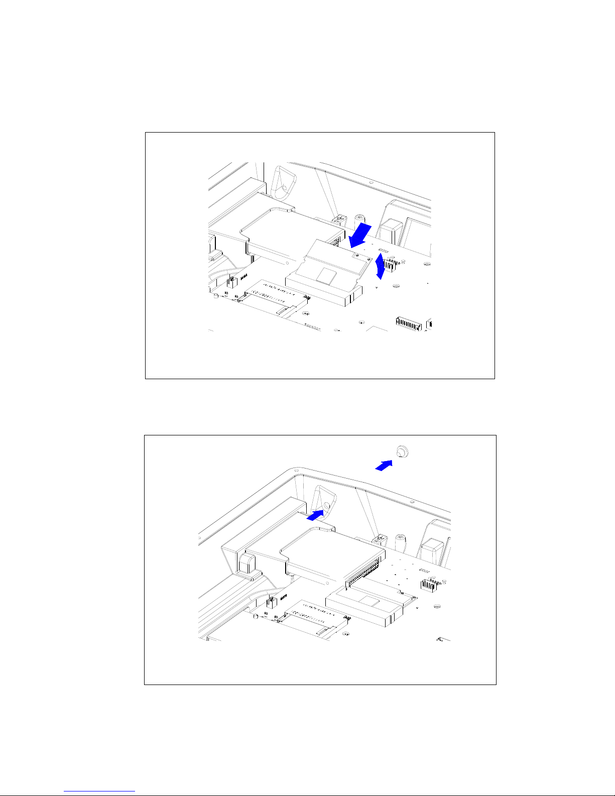
2.7 Wireless LAN Card Installation
2.7.1. Insert wireless LAN card into the unit.
2.7.2 Remove Antenna Cover from chassis.
Page 19
SENOR TECH CO., LTD.
iSPOS User’s manual
19
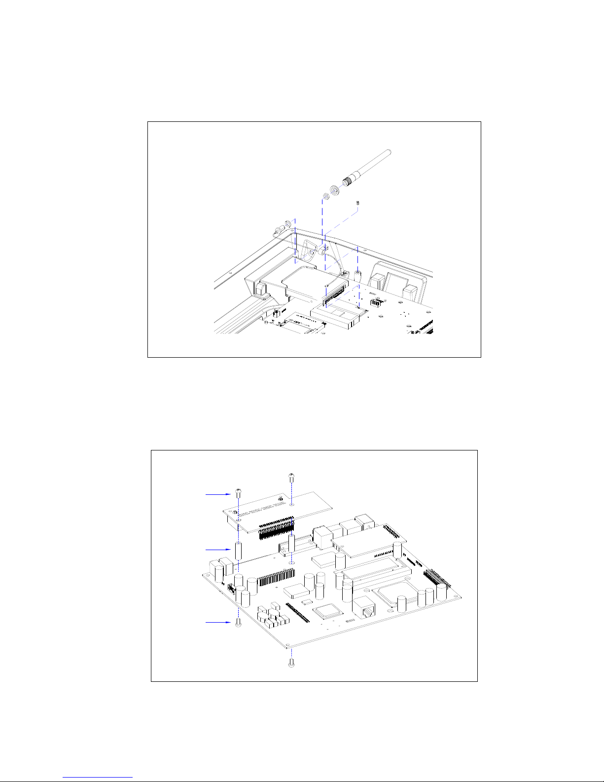
2.7.3 Install the Water Sealing Washer and Antenna. Connect the Antenna
Connector to Wireless LAN card.
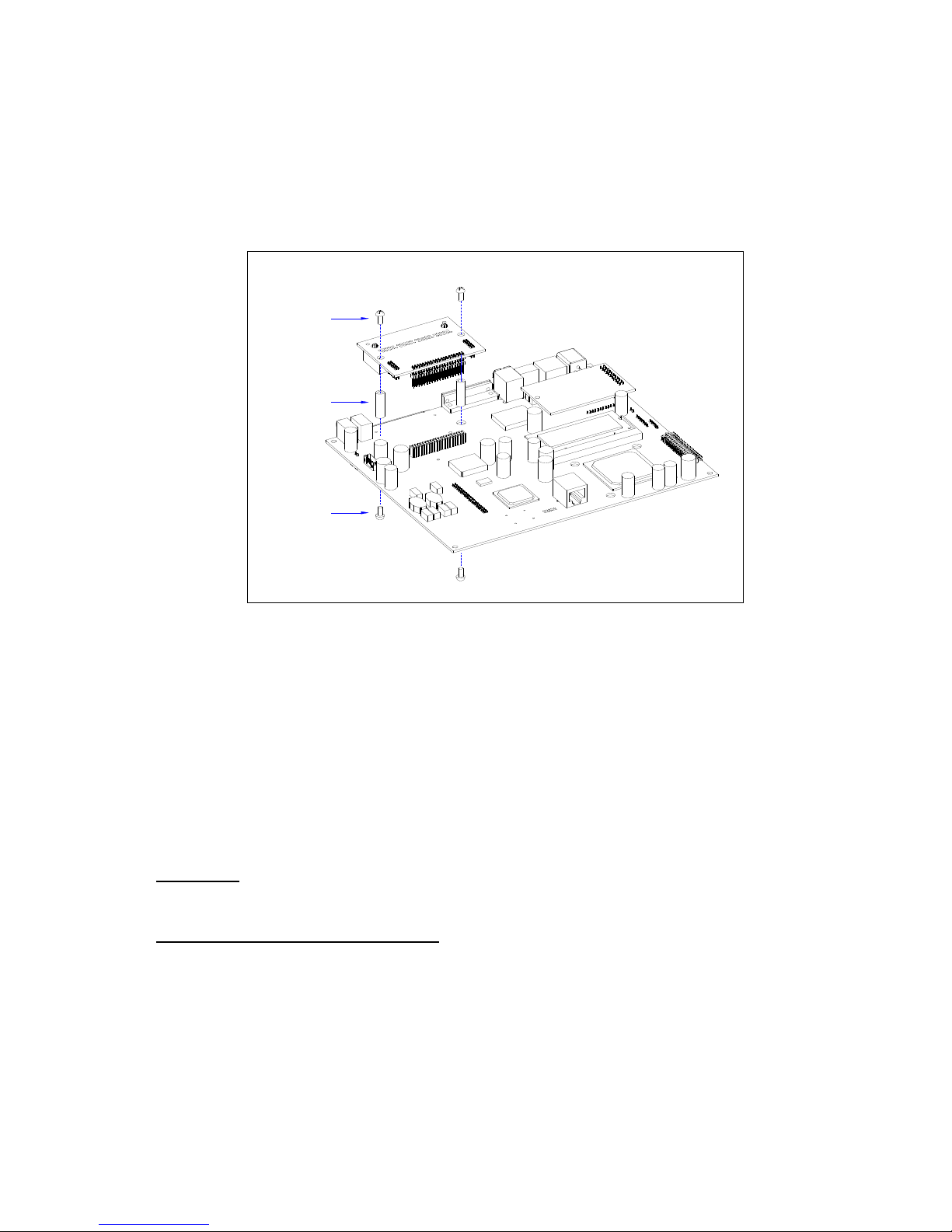
2.8 Modem Card Installation
Install Modem card as shown in diagram (2). Attach plastic standoffs
followed by the plastic screws.
plastic boss
plastic screw
plastic screw
Diagram (2) : Modem card installation
Page 20
SENOR TECH CO., LTD.
iSPOS User’s manual
20
2.9 Cash drawer Board Installation
(Model: GMB-A232CDV1)
Install Cash drawer board as shown in diagram (3). Attach plastic
standoffs followed by the plastic screws.
plastic screw
plastic screw
plastic boss
Diagram (3) : Cash drawer board installation.
3. INSTALLATION
It is important that before installation the iSPOS terminal's position and
environment be considered.
3.1 Pre-installation
Location Ensure that as with any computer equipment, the iSPOS terminal
is positioned in a clean and well-ventilated area away from direct sunlight
Operator’s Comfort and Safety
Operator comfort and safety should always
be of the highest priority when deciding on the location and layout of the
iSPOS system. Please note the comfortable distance between the
operator and the touch screen; the operator should not have to stretch to
reach the screen but also should not be in a cramped position. The height
of the terminal should be such that the operator can view the screen at
right angles.
Page 21

SENOR TECH CO., LTD.
iSPOS User’s manual
21
Clearances The iSPOS terminal should be located where there is
adequate clearance for ventilation around the terminal. Similarly, clearance
around the power supply for ventilation, as well as access to the power
switch, indicators and connectors should be allowed for. Additional
consideration should be given to ensuring nothing can be placed over the
fan or vent holes, e.g. paper, rags etc.
Cable Routing
In most cases the position of printers, scanners etc. will
make it necessary that the cabling will have to be run through counter
dividing panels and shelves. Try to keep these runs as short as possible,
while avoiding stretching or crimping the cable. Keep the iSPOS data
cables separated from those for other equipment, in particular motors,
lighting, refrigeration etc.
Mains AC Power Supply
AC supply to the iSPOS system should be a
dedicated feed from the main switchboard. Do not connect any other
equipment to this feed or damage to the iSPOS terminal or its peripherals
may result. A hint is to clearly identify each iSPOS terminal power outlet as
a dedicated point. The supply should have a reliable ground at the
switchboard.
Configuration
Any number of methods can be used to install the iSPOS,
dependant on countertop configuration, user preference and peripherals
connected. It can simply sit on the countertop, in which case care must be
taken to ensure it cannot be knocked off the countertop when bumped. It
can also be fixed to the countertop using the provided base unit or
mounted on vesa bracket or arm. It would be impossible to cover every
installation situation in this manual so each should be considered
individually
.
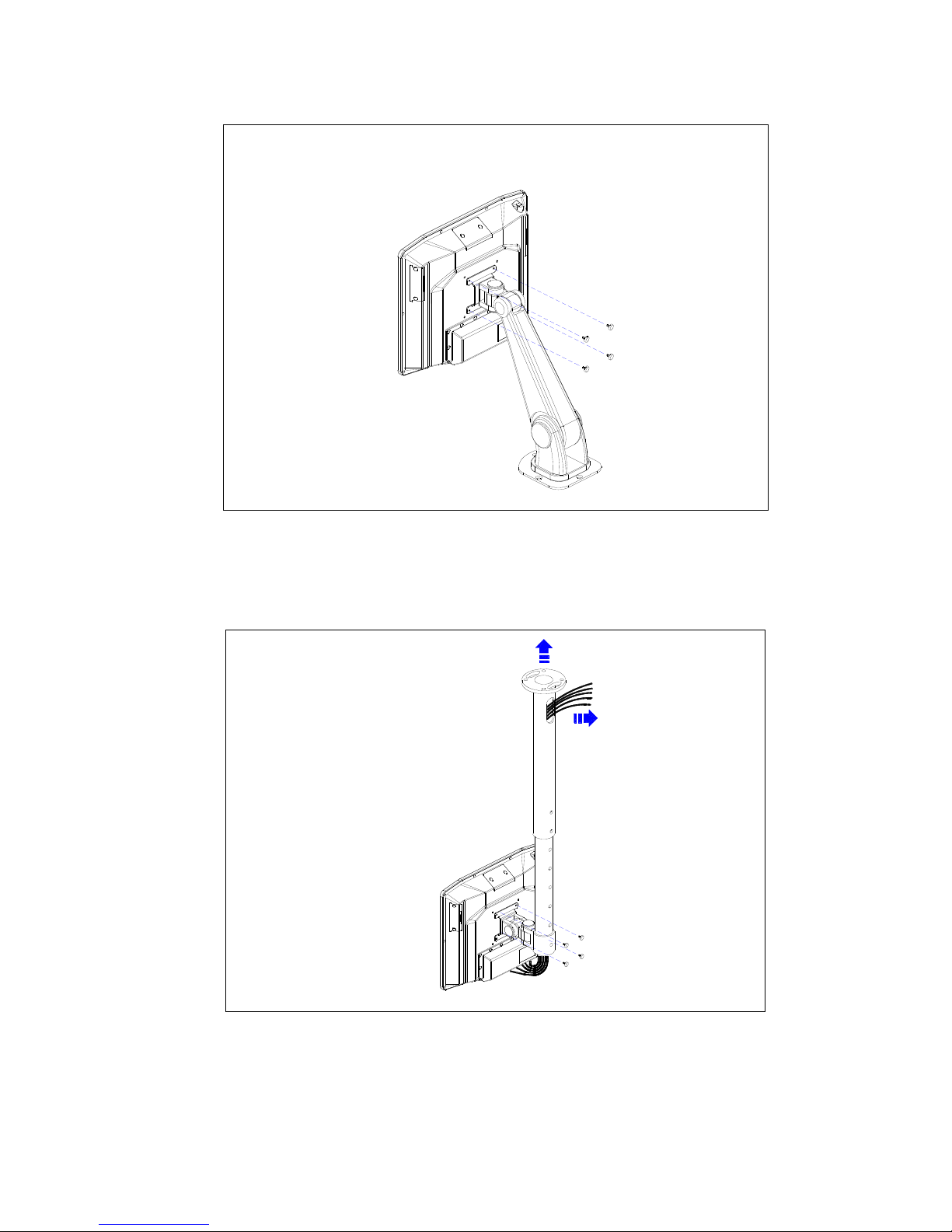
3.2 Mounting
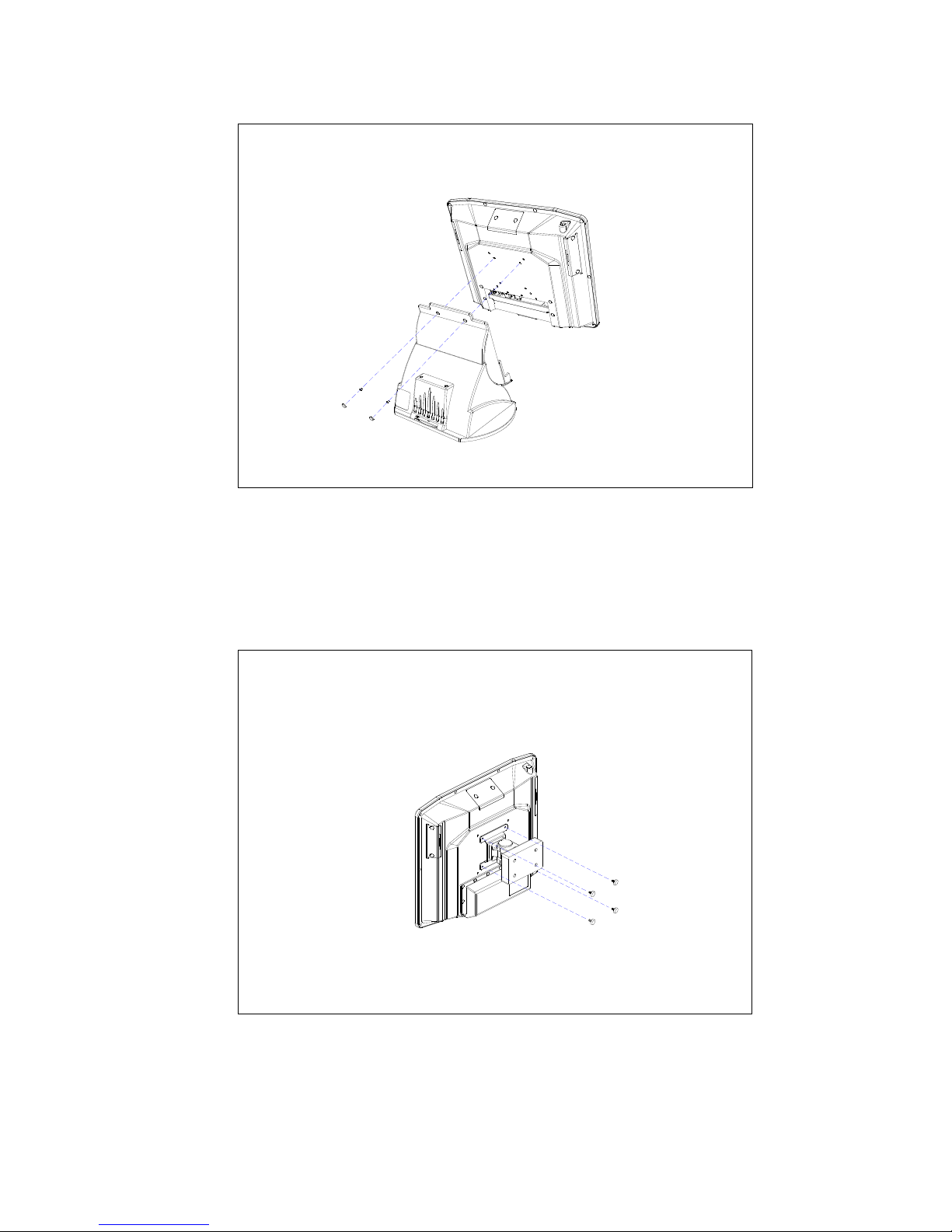
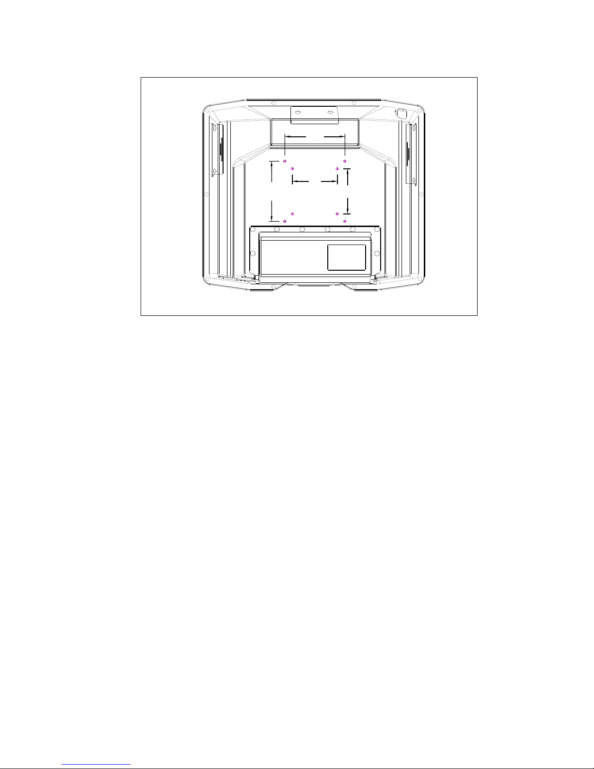
The iSPOS is designed to be fitted with a base unit or with a VESA
standard mounting bracket or arm (75 mm X 75 mm; 100 mm X 100 mm) if
required.
Unscrew the two screws securing the base unit to the LCD panel.
Separate the LCD Panel from the base unit by lifting the LCD panel.
Page 22
SENOR TECH CO., LTD.
iSPOS User’s manual
22
Use four M4 screws to secure the iSPOS LCD panel onto any VESA
standard mounting bracket or arm.
Mounting on the wall
Page 23
SENOR TECH CO., LTD.
iSPOS User’s manual
23
Mounting on the desk
Mounting on the ceiling
Cable exit can be
either from the side
or the top.
The cable assembling
sequence as follows.
1. DC IN cable x 1
2. SCSI Printer cable x 1
3. RS232 x 4
4. LAN x 1
5. PS2/KB x 1
6. USB cable x 2
7. Audio cable x 1
8. Microphone cable x 1
Page 24
SENOR TECH CO., LTD.
iSPOS User’s manual
24
75
75
100
100
Note: the length of screws must not exceed 6mm.
The location of peripherals should be decided upon, consideration for
operator safety and comfort should be observed and the length and
location of data cables to each peripheral device should be considered.
Once the installation method and configuration has been chosen,
modifications to the counter can be made using each peripheral
manufacturer's installation instructions. Remember to allow for cable runs
through the countertop and any shelving. Usually there will be two cables
per device, one for power and one for data.
Page 25

SENOR TECH CO., LTD.
iSPOS User’s manual
25
4. REGULAR MAINTENANCE
To ensure reliable operation, the iSPOS should be regularly maintained,
cleaning both internally and external and checking that all connections are
secure and no cables are damaged
4.1 Cleaning
The iSPOS should be cleaned with a soft and slightly damp cloth. DO NOT
use solvents or abrasives and DO NOT spray any substance directly onto
the iSPOS terminal.
The touch screen should be cleaned with a soft, slightly damp cloth in a
circular motion, from its center to outer edges.
4.2 Touch Screen
Caring For The Touch Screen To keep the touch screen in good working
order, use only the ball of the finger to activate onscreen buttons, never
use pins, pens, pencils or the like on the touch screen and regularly clean
with a soft slightly damp cloth. The activation pressure for the touch screen
is 5.5 grams therefore only a light touch is required, never hit the screen or
apply excessive pressure or permanent damage will occur. If there is
difficulty activating the on screen buttons, the touch screen may need
calibrating.
Cleaning
Clean with a soft, slightly damp cloth, wipe gently in a circular
motion from the center of the screen to the outside edges. Do not use
solvents or abrasives.
Page 26

SENOR TECH CO., LTD.
iSPOS User’s manual
26
5. TROUBLESHOOTING
This section contains information that will help identify and correct
problems that may arise with the iSPOS.
If none of the recommendations in this chapter help identify and resolve
the problem, contact with the Service Dept. of your Supplier. Before
contacting, write down the serial number of the unit, the exact syntax of
any error messages that may be displayed, all symptoms of the problem
and details of the system configuration. The more information you can
provide, the quicker the dealer can identify the source of the problem and
provide a solution.
5.1 General Troubleshooting
Problem
Suggestion
You turn on the iSPOS, but it does not
respond (e.g. Nothing on either display,
no beeps).
Make sure the power cord is properly connected
to the iSPOS power Inlet and AC power outlet.
Make sure the power button is ON, and is not in
sleep mode.
External devices connected to the iSPOS
do not work
Make sure all external devices are connected
correctly as required by the application. Make
sure the device is connected to Securely to a
known working AC wall outlet.
An unrecoverable disk error occurs after
using for a prolonged period of time
Turn off the iSPOS and let it cool for a few
minutes, check that the removable hard disk
drive is firmly seated in the drive bay and
nothing is obstructing the airflow to the unit.
The iSPOS reports a parity error and the
program stops running.
Turn off the iSPOS, unplug its power cord and
remove cover to access the RAM SODIMM
memory module. Gently press down on each
removable SIMM on the mother board. If the
error persists, remove and reinstall the
SODIMM, making sure to properly align it in the
socket
5.2 LCD Troubleshooting
LCD Problem Suggestion
The LCD remains blank . Touch the screen to ensure the Power
Management is not active Make sure the
brightness and contrast settings are not set to
darkest setting, if they are they may give the
impression that the LCD is not working properly.
LCD screen not display. Check M/B SW2 (Display Mode) setting is
properly.
Page 27

SENOR TECH CO., LTD.
iSPOS User’s manual
27
5.3 Disk Drive Troubleshooting
Disk Drive Problem Suggestion
When the system is powered up, trying to
boot from the Hard Disk results in the
message: "Hard Disk failure. Strike the F1
key to continue” When the F1 key is
pressed, the message: "No boot device
available - strike F1 to continue”
Power off and reseat the hard disk drive. Check
the CMOS setup is correct for the installed
drive. If possible try another known working
hard drive. If the new drive still doesn't work the
problem will be internal either the Hard Disk
"bay” is faulty or the motherboard is faulty. If the
replacement drive works the original drive is
faulty, partition and format the drive (using the
DOS commands FDISK and FORMAT,
described in the DOS manual). WARNING : All
Data and Programs will be lost. If partitioning
and formatting doesn't correct the problem the
drive will need to be replaced
5.4 RAM Troubleshooting
RAM Problem Suggestion
The iSPOS beeps continuously when it is
turned on
For wireless I/R keyboard, move keyboard away
from Upper Part, if problem is fixed, check for
stuck keys or low batteries in the keyboard. For
wired keyboard unplug the keyboard, if problem
is fixed check for stuck keys on the keyboard. If
problem was not fixed, turn off the iSPOS,
unplug the power cord and remove the covers
to gain access to the motherboard's SODIMM
RAM modules. Carefully reseat the modules.
The iSPOS beeps four or seven times and
the LCD will not work.
As Above.
When the iSPOS is turned on, the
message "Invalid configuration information
- please run setup utility” is displayed, or
the amount of base memory and extended
memory displayed is incorrect
Run the CMOS Setup utility, make sure the
amount of base memory defined by the setup
utility is correct, if not alter them. Be sure the
amount entered matches the actual amount of
system memory on the motherboard. If the
problem persists, turn off the Upper Part, unplug
the power cord and remove the covers to gain
access to the motherboard's SIMM RAM
modules. Carefully reseat the modules. If the
problem continues, remove each SODIMM and
check for damage, the removable SODIMM may
be defective.
5.5 Serial Port Troubleshooting
Serial Port Problem Suggestion
A serial device is connected to the iSPOS,
but the serial device does not respond to
the data it is receiving from the iSPOS or
the iSPOS does not respond to data being
sent by the device.
Verify that power is being applied to the serial
device and that it is turned on. Make sure the
cable connecting the serial device to the Upper
Part serial port is properly configured for the
application. Also, Make sure the cable is
connected securely at both the Upper Part and
serial device.. Try another cable to see if the
problem is resolved. Make sure the application
software is sending data to the correct port.
Page 28

SENOR TECH CO., LTD.
iSPOS User’s manual
28
5.6 Error Messages
Error Message
Possible Cause
C: drive error Power off and reseat the hard disk drive. Run
CMOS setup utility and ensure the correct hard
disk type is entered (Auto Detect). If possible try
another known working hard drive in the iSPOS
If the new drive still does not work the problem
will be internal to the iSPOS, either the Hard
Disk "bay" is faulty or the motherboard is faulty.
If the replacement drive works, replace the
original drive and run DOS scandisk on the
drive, if the problem is not fixed, the drive is
faulty and will need to be replaced.
C: drive failure Power off and reseat the hard disk drive. Run
CMOS setup utility and ensure the correct hard
disk type is entered (Auto Detect). If possible try
another known working hard drive in the iSPOS
If the new drive still doesn't work the problem
will be internal to the iSPOS, either the Hard
Disk "bay" is faulty or the motherboard is faulty.
If the replacement drive works, replace the
original drive and run DOS scandisk on the
drive, if the problem is not fixed, the drive is
faulty and will need to be replaced.
Keyboard error Ensure the keyboard loopback plug and loop of
card reader connected properly
CMOS battery state low Make sure the battery is working properly. Run
the CMOS Setup utility and enter the correct
parameters.
CMOS system options not set Make sure the battery is working properly. Run
the CMOS Setup utility and enter the correct
parameters
CMOS display type mismatch
Make sure the battery is working properly. Run
the CMOS Setup utility and enter the correct
parameters.
Page 29
SENOR TECH CO., LTD.
iSPOS User’s manual
29
AUTION
z
If any abnormal power conditions or blackout occur during
operation, immediately switch OFF the iSPOS unit at the main
power switch. Once normal power is restored, restart the iSPOS
unit.
If the Keyboard Loopback Plug has been removed from the PS/2
keyboard port for any reason, reinstall to avoid keyboard error
message during boot up. If the Keyboard Loopback Plug has been
lost, the Keyboard Y Cable can be used as an interim solution.
Keyboard Loopback Plug Keyboard Y Cable
z
Page 30
SENOR TECH CO., LTD.
iSPOS User’s manual
30
Precaution
! Specifications are subject to change without notice.
! Avoid exposing the product to direct sunlight and do not use the product
near areas of high moisture.
! Do not block the unit’s ventilation openings.
! Do not attempt to disassemble or modify this product by yourself, as
doing so may expose you to an electric shock. All servicing should be
performed by qualified personnel and should conform to all local codes.
! iSPOS is equipped with the specific power adapter (12V 5A). Do not use
any other type of adapter to operate the product. It is recommended that
you only use the manufacturer’s supplied adapter.
! If any abnormal power conditions or blackouts occur during operation,
disconnect unit at the AC source immediately. Once normal power is
restored, reconnect the AC source.
! To avoid unit failure or intermittent operation, check power and other I/O
cables are connected correctly.
! Always unplug the power cord from the AC outlet before cleaning the
product. Use a soft cloth to clean the product. Do not use solvents or
abrasives and do not spray or pour any liquid directly onto the product’s
screen or case.
 Loading...