

Page 1

Senop Hyperspectral Camera
HSC-2
User Guide
Version: 30 / 5.4.2019 DRAFT
Page 2

THE SPECIFICATIONS AND INFORMATION REGARDING THE PRODUCTS IN THIS MANUAL ARE SUBJECT TO
CHANGE WITHOUT NOTICE.
ALL STATEMENTS, INFORMATION, AND RECOMMENDATIONS IN THIS MANUAL ARE BELIEVED TO BE
ACCURATE BUT ARE PRESENTED WITHOUT WARRANTY OF ANYKIND, EXPRESS OR IMPLIED.
USERS MUST TAKE FULL RESPONSIBILITY FOR THEIR APPLICATION OF ANY PRODUCTS.
THE SOFTWARE LICENSE AND LIMITED WARRANTY FOR THE ACCOMPANYING PRODUCT ARE
INCORPORATED HEREIN BY THIS REFERENCE. IF YOU ARE UNABLE TO LOCATE THE SOFTWARE LICENSE OR
LIMITED WARRANTY, CONTACT YOUR REPRESENTATIVE FOR A COPY.
NOTWITHSTANDING ANY OTHER WARRANTY HEREIN, ALL DOCUMENT FILES AND SOFTWARE OF THESE
SUPPLIERS ARE PROVIDED “AS IS" WITH ALL FAULTS.
SENOP DISCLAIM ALL WARRANTIES, EXPRESSED OR IMPLIED, INCLUDING, WITHOUT LIMITATION, THOSE OF
MERCHANTABILITY, FITNESS FOR A PARTICULAR PURPOSE AND NONINFRINGEMENT OR ARISING FROM A
COURSE OF DEALING, USAGE, OR TRADE PRACTICE.
IN NO EVENT SHALL SENOP OR ITS SUPPLIERS BE LIABLE FOR ANY INDIRECT, SPECIAL, CONSEQUENTIAL, OR
INCIDENTAL DAMAGES, INCLUDING, WITHOUT LIMITATION, LOST PROFITS OR LOSS OR DAMAGE TO DATA
ARISING OUT OF THE USE OR INABILITY TO USE THIS MANUAL, EVEN IF SENOP OR ITS SUPPLIERS HAVE
BEEN ADVISED OF THE POSSIBILITY OF SUCH DAMAGES.
Any Internet Protocol (IP) addresses and phone numbers used in this document are not intended to be
actual addresses and phone numbers. Any examples, command display output, diagrams, and other figures
included in the document are shown for illustrative purposes only. Any use of actual IP addresses or phone
numbers in illustrative content is unintentional and coincidental.
Senop and the Senop logo are trademarks or registered trademarks of Senop Oy.
The use of the word partner does not imply a partnership relationship between Senop and any other
company
© 2019 Senop
All rights reserved
2 25247
Page 3

Table of Contents
Purpose .............................................................................................................................................................. 5
Key Features of Device ...................................................................................................................................... 5
Handling Hyperspectral Camera ........................................................................................................................ 5
Regulatory information ..................................................................................................................................... 6
CE ................................................................................................................................................................... 6
FCC ................................................................................................................................................................. 6
FCC Information for the User .................................................................................................................... 6
FCC compliance statement: ....................................................................................................................... 6
Safety information ............................................................................................................................................. 7
General Safety ............................................................................................................................................... 7
Hot Surface .................................................................................................................................................... 7
Socket outlet .................................................................................................................................................. 7
Warranty Statement .......................................................................................................................................... 8
Open Source Software Notice ........................................................................................................................... 8
Specifications ..................................................................................................................................................... 9
Powering ........................................................................................................................................................ 9
Operation conditions ..................................................................................................................................... 9
Optics ............................................................................................................................................................. 9
Imaging capability .......................................................................................................................................... 9
Spectral capability ......................................................................................................................................... 9
Connections ................................................................................................................................................. 10
Peripherals ................................................................................................................................................... 10
Device UI ...................................................................................................................................................... 10
Sales Package Contents ............................................................................................................................... 10
Display and Keyboard ...................................................................................................................................... 12
Connections and Connectors........................................................................................................................... 13
AUX connector ................................................................................................................................................. 14
AUX connector functions ............................................................................................................................. 14
AUX connector specification ....................................................................................................................... 14
AUX connector pin order ............................................................................................................................. 15
AUX TRIG pin usage principle ...................................................................................................................... 15
Attaching the HSC-2 to Drone. ........................................................................................................................ 16
HSC-2 requirements when used in drone: .................................................................................................. 16
3 25247
Page 4

Mechanical fixing ......................................................................................................................................... 16
Electrical connection ................................................................................................................................... 17
GPS in Drone Use ......................................................................................................................................... 17
DJI Matrice 600 ............................................................................................................................................ 18
Senop HSI Software ......................................................................................................................................... 20
HSI Data Visualization view ......................................................................................................................... 20
Main menu .............................................................................................................................................. 20
Connection Status Indicator .................................................................................................................... 21
Data Visualization Toolbar ....................................................................................................................... 21
Visualization area .................................................................................................................................... 21
Exposure slider ........................................................................................................................................ 21
Data cube info ......................................................................................................................................... 21
Sequence toolbar ..................................................................................................................................... 22
Sequence visualization ............................................................................................................................ 22
Sequence slider........................................................................................................................................ 22
Exposure setting & Add to Script ............................................................................................................. 22
Script Creator ........................................................................................................................................... 23
Quick start guide.............................................................................................................................................. 25
Connecting to the HSC-2 ............................................................................................................................. 25
Taking a snapshot using the default Sequence ........................................................................................... 26
Creating and measuring a custom script ......................................................................................................... 27
Creating a custom sequence ....................................................................................................................... 27
Creating a custom script .............................................................................................................................. 28
Measuring the script using the Senop HSI-2 software ............................................................................ 28
Measuring the script using the HSC-2 camera menu .............................................................................. 29
Importing the data to the PC ................................................................................................................... 29
Open the data cube in HSI-2 software ........................................................................................................ 30
ENVI Data type ............................................................................................................................................. 31
Updating the device software (firmware) ................................................................................................... 33
4 25247
Page 5

Purpose
This guide will help you to start the use of the Senop Hyperspectral Camera HSC-2 and the Senop HSI-2
software.
Key Features of Device
The device is meant for Hyperspectral imaging. It can take images of specified wavelengths inside its
operational wavelength range. Device can change wavelength rapidly and use pre-set list of wavelengths to
construct (envi) data cubes where same or almost same object or landscape is represented with multiple
narrow band wavelengths.
The Senop Hyperspectral camera can work independently with only power supplied to it, with integrated
memory or it can be used with computer. It can be connected either directly to a computer or to an Ethernet
network.
Handling Hyperspectral Camera
This device is a precision instrument. Do not drop it or subject it to physical shock.
Device is calibrated to operate as specified in this document. Re-calibration is preferred occasionally
depending conditions where used and after physical shock, vibration etc.
5 25247
Page 6

Regulatory information
This Device is tested under CE & FCC requirements as descripted below:
CE
Hereby, SENOP declares that the HSC-2 is in compliance with directives and regulations listed below
• 2014/53/EU (The Radio Equipment)
• 2011/65/EU (RoHS)
• 2012/19/EU (WEEE)
In accordance with Article 11(2) in Directive 2012/19/EU (WEEE), products were marked with following
symbol: a cross-out wheeled waste bin with a bar beneath as below:
The full text of the EU declaration of conformity is available at the following internet address:
http://senop.fi/compliance
FCC
FCC Information for the User
This product does not contain any user serviceable parts
FCC compliance statement:
This device complies with Part 15 of the FCC Rules. Operation is subject to the following two conditions: (1)
this device may not cause harmful interference, and (2) this device must accept any interference received,
including interference that may cause undesired operation.
6 25247
Page 7

Safety information
Use the following safety guidelines to help ensure your own personal safety and to help protect your
equipment and working environment from potential damage.
IMPORTANT NOTICE FOR USE IN HEALTHCARE ENVIRONMENTS:
Senop HSC-2 product is not a medical device and is not listed under UL or IEC 60601 (or equivalent). As a
result, it must not be used within 6 feet of a patient or in a manner that directly or indirectly contacts a
patient.
General Safety
Place the equipment on a proper stand or holder, like tri-pod, or gimbal in drone. Fix it securely. Never place
it in a closed- unit, or on a sofa, rug or bed. The equipment is not indented to be used as hand-held.
Equipment metal bottom plate may be warm during normal operation.
Leave 10 cm (4 in) minimum of clearance on all sides of the device to permit the airflow required for proper
ventilation. Restricting airflow can damage the equipment or cause a fire.
Do not stack equipment or place equipment so close together that it is subject to recirculated or preheated
air. Keep your device away from radiators and heat sources. Keep your equipment away from extremely hot
or cold temperatures to ensure that it is used within the specified operating range.
Ensure that nothing rests on your equipment's cables and that the cables are not located where they can be
stepped on or tripped over.
Do not use your equipment in a wet environment, for example, near a bath tub, sink, or swimming pool or in
a wet basement.
Do not spill food or liquids on your equipment.
If your equipment does not operate normally - in particular, if there are any unusual sounds or smells coming
from it - unplug it immediately and contact an authorized dealer.
Hot Surface
There is “Hot Surface” label in device metal bottom plate
Hot Surface label indicates possibility to surface get uncomfortable hot or even
cause burn when touched. Especially if air circulation around device is prevented
and device is used long times continuously.
Be careful not to touch any hot surfaces!
Socket outlet
Do not install or use in an area that impedes access to the power plug. Disconnecting the power plug is the
only way to completely remove power to the product and the plug must be readily accessible at all times!
7 25247
Page 8

Warranty Statement
• Warranty period 12 months, unless otherwise agreed.
• Registration of the product may be required to validate the warranty
• Proof of purchase may be required
• The repair or replacement of a faulty product within the warranty period remains at the discretion
of Senop
• The Senop HSC-2 warranty covers defects in parts or workmanship but does not cover fair wear and
tear, defect resulting from misuse, unauthorized modification, operation or storage outside the
environment specification for the product or in-transit damage.
Open Source Software Notice
This product contains Senop HSI-2 software which is licensed under the GPL and LGPL. Copy of the licenses
is provided along with this product. Also available on website https://www.gnu.org/licenses/.
Senop Oy will provide open source code used in product for charge covering the cost of performing such
distribution upon request. This offer is valid for three (3) years from the date on which the product is
purchased.
Contact: http://senop.fi/
8 25247
Page 9

Specifications
• Frame Based Digital Hyperspectral camera
o True global shutter snapshot sensor.
• Size: 199,5mm x 130,9mm x 97,2mm (73mm without lens)
• Weight 990 g (without connector cover)
Powering
• Device Voltage supply 7 – 17 VDC
• Maximum current consumption (@7V) peak 2,2A, nominal 1,6A
• Maximum power consumption 12W, peak 16W
• Wall power 100-230 VAC 50/60Hz
Operation conditions
• Temperature range 5 – 40°C in free air
o If temperature range is exceeded, imaging will be inhibited to prevent damages
• Relative humidity less than 85%, not condensing
Optics
• F#3,28
• FOV 36,8 deg
• Focus distance: 30cm to ∞, limited FOV with less than 30cm distances
Imaging capability
• Image frame size: 1024 x 1024 pixels
• Frame rate (single image or video)
o 12-bit frame: max 74 f/s
o 10-bit image: max 149 f/s
o min 1 f/s
o viewfinder gets slow if the frame rate is set too slow
• Internal memory, with maximum frame rate
o 12bit: 1h45min
o 10bit: 1h17min
• Exposure time: can be set freely
o maximum frame rate may be limited if exposure time is long
• Radiance accuracy for all pixels < 5% (12bit), < 10% (10bit)
Spectral capability
• Wavelength area (Serie A)
o 500nm – 900nm
9 25247
Page 10

o Up to 1000 spectral bands
o normal, narrow and wide FWHM selectable per wavelength
• Spectral FWHM bandwidth: Narrow <10nm, Normal <15nm, Wide <20nm (where applicable)
• Spectral accuracy over operating ambient temperature range <2nm
• All pixels are true pixel, no interpolation used
Connections
• Gigabit ethernet connection RJ-45
• USB 2.0 type-C
• mini-Displayport v1.2
• AUX port with UART, Trigger, Sync and 2GPIO pins.
• MMCX for external GPS antenna, if needed
Peripherals
• Internal Hard Drive 1TB
• Integrated GPS
o Internal antenna for GPS
o Internal antenna is located next GPS connector, facing up.
o External antenna (not included) thru MMCX connector for GPS and Glonass
• Integrated IMU
o Accuracy typically 1°
Device UI
• Display
o Resolution, 128 x 64 pixels
o Black and white
• 4 button, (up, down, back, select)
• Indicator RGB -led
Sales Package Contents
• Senop HSC-2-x Hyper Spectral Camera, where x is
o C – 500nm – 900nm
• Wall Power Unit
o 90 - 264 VAC / 12VDC 24W
o CUI SMI24-12-V-P6
• Power cable
o 2.5mm ID, 5.5mm OD Plug to Wire Leads Flat 6.0' (1.83m)
o Tensility 10-01060 (or similar)
• Ethernet Cable
o CAT 6, 3m (9,84’), Double Shielded, Blue
o Assmann WSW Components A-MCSSP60030/B (or similar)
• IO Cable
o Samtec S2SDT. Teflon insulated wires.
• USB memory with softwares and manual
• Camera Case
10 25247
Page 11

o
Customized Peli 1400
11 25247
Page 12

Display and Keyboard
Ok /Select
Cancel
When HSC-2 Hyperspectral Camera is not controlled directly by computer there are certain functions that
can be operated from the device own user interface
• Run script
• Single shot
• Settings for
o Time and Date
o Ethernet
o Camera
Bit Depth
Frame rate
o GPS
o Storage
• Data storage
• Display port
• About
Up
Down
12 25247
Page 13

Connections and Connectors
Ethernet
RJ-45
Power Supply
7-17V
20W
There are six connectors on the device
• Ethernet RJ 45 connector
• Power connector
• USB connector
• Display port connector
• AUX-Connector
• GPS antenna connector
USB-C
Mini
DisplaPort
AUX
connector
External
GPS
antenna
MMCX
13 25247
Page 14

AUX connector
AUX connector functions
• TRIG, Input, Realtime pulse, trigger to enable script
• SYNC, Output, Realtime pulse, to Synchronize device operation
• 2 IO pins, direction configurable, to control selectable function. No SW support currently.
• UART to communication. No SW Support currently.
• Interface voltage supply (Input).
AUX connector specification
• Voltage should be supplied for interface from device connected to.
o Connector is isolated from HSC-2 voltage domains.
o Voltage range: 1.65V – 5.5V, Used buffer: SN74LVC1T45
o Interface is enabled only when voltage is supplied.
• Connector type is Samtec T2M 2.00 mm Tiger Eye™ 8 pin.
o Supplied cable type is Samtec S2SDT. Teflon insulated wires.
• Absolute Maximum Ratings
o Supply voltage, Input voltage -0.5V – 6.5V
o Continuous output current 50mA
o Stresses beyond Absolute Maximum Ratings may cause permanent damage to the device
• Recommended Operating Conditions
o Supply voltage 1.65V – 5.5V
o High-level input voltage
When VccI is 1.65 to 1.95V: Min VccI× 0.65V
When VccI is 2.3 to 2.7V: Min 1.7V
When VccI is 3 to 3.6V: Min 2V
When VccI is 4.5 to 5.5 V: Min VccI × 0.7
o Low-level input voltage
When VccI is 1.65 to 1.95V: Max VccI× 0.35V
When VccI is 2.3 to 2.7V: Max 0.7V
When VccI is 3 to 3.6V: Max 0.8V
When VccI is 4.5 to 5.5 V: Max VccI × 0.3
o Output current, High and Low level
When VccI is 1.65 to 1.95V: Max |4mA|
When VccI is 2.3 to 2.7V: Max |8mA|
When VccI is 3 to 3.6V: Max |24mA|
When VccI is 4.5 to 5.5 V: Max |32mA|
• Pin configuration
o Pin 1 – SYNC, Output, Function configurable, Synchronous, 50Ω serial resistor in buffer
o Pin 2 – Voltage (VccI), Input 1.65V – 5.5VDC, 300nF Filtering.
o Pin 3 – TRIG, Input, Function configurable, Synchronous, 10kΩ PD to GND
o Pin 4 – IO2, Input or Output, Function configurable, 10kΩ PU to VccI
o Pin 5 – RX, Input, UART RX pin, 10kΩ PU to VccI
o Pin 6 – IO1, Input or Output, Function configurable, 10kΩ PU to VccI
o Pin 7 – TX, Output, UART TX pin, 50Ω serial resistor in buffer
14 25247
Page 15
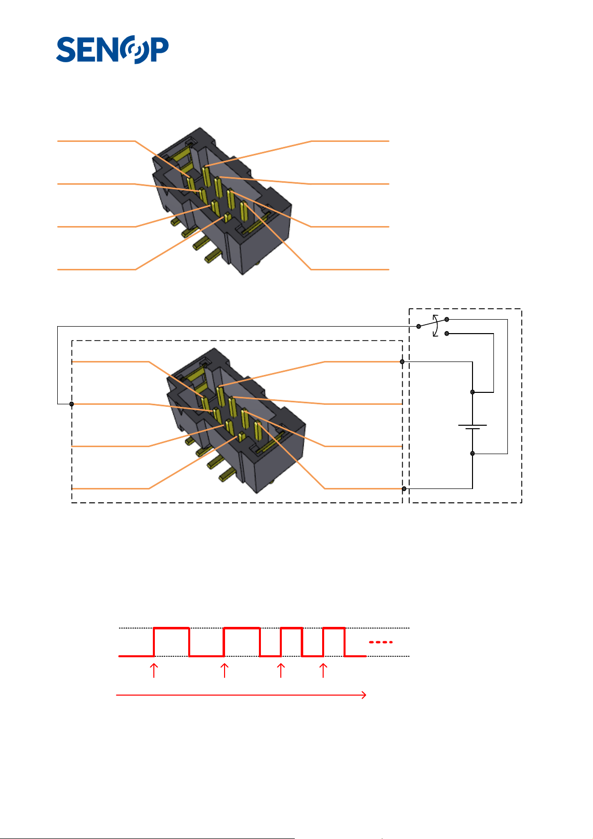
o Pin 8 – GND, Common GND to device.
AUX connector pin order
Pin 1 - SYNC
Pin 3 - TRIG
Pin 5 - RX
Pin 7 - TX
AUX TRIG pin usage principle
Pin 1 - SYNC
Pin 3 - TRIG
Pin 2 - Voltage
Pin 4 - IO 2
Pin 6 - IO 1
Pin 8 - GND
Pin 2 - Voltage
Pin 4 - IO 2
IO-Power 2.8-5V
Pin 5 - RX
Pin 7 - TX
HSC-2 Controlling device
• TRIG pin is functional only when IO power (1.65V-5.5V) for interface is supplied
• TRIG pin should be kept all the time in either GND or IO-Power voltage (1,65V-6.5V)
o This can be done for example ON-ON type control
o TRIG pin is tied to GND with 10kΩ resistor internally
• TRIG pin impedance is high, IO-Power consumption is very low.
• TRIG IO power can be connected independently, regardless of HSC-2 power supply
IO-Power 2.8-5V
GND
Trigger event
Time
• Only rising edge trigger is supported by SW currently
• It is not possible to trig new sequence when previous sequence is still ongoing.
Trigger event Trigger eventTrigger event
Pin 6 - IO 1
Pin 8 - GND
15 25247
Page 16
Attaching the HSC-2 to a Drone.
When using the HSC-2 camera in drones it is always advisable to use professional gimbal, compatible with
drone. Gimbal insulate drone vibrations and keep camera steady. Use also high-quality drones.
HSC-2 requirements when used in drone:
• Safe and sturdy installation. The HSC-2 will not survive dropping from heights.
• Power supply. HSC-2 needs power supplied from external source.
o Device Voltage supply 7 – 17 VDC
o Maximum power consumption 12W, peak 16W
o Power consumption is highly depended on the usage of the device.
• Good weather
o HSC-2 is a high precision device and not insulated from water
o Hyperspectral imaging during rain will not work.
Mechanical fixing
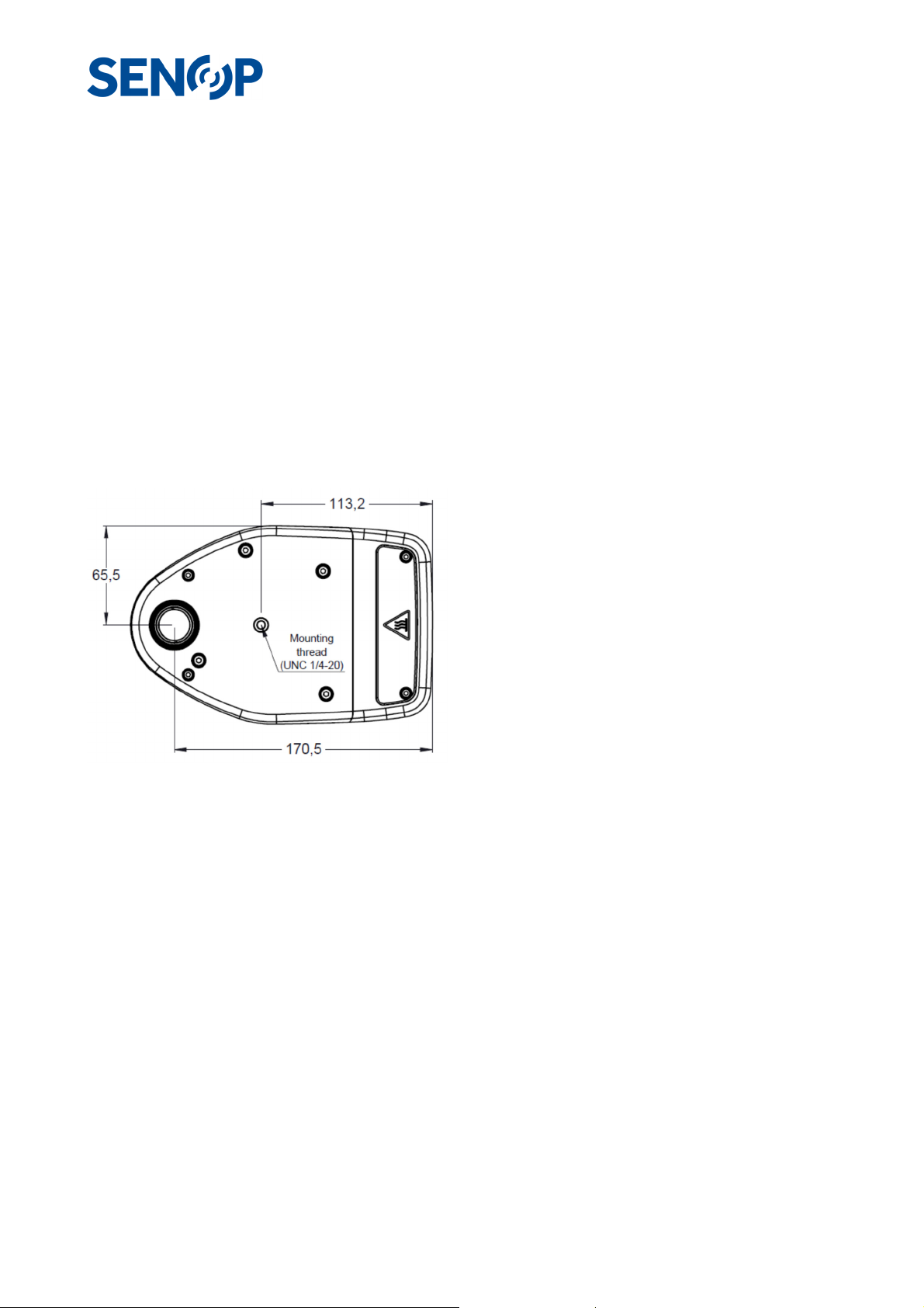
There is a UNC ¼-20 mounting thread installed in
device aluminum base plate. It is advisable to attach
baseplate directly against gimbal (metal) fixing plate.
This also improve cooling for device. Do not cover base
plate with insulating material, like printed plastic
plates. This may reduce device operation or even
cause thermal shutdown during operation.
Fixing may be secured with for example strap over
device. Locate strap front side of display area. There
may be other “Upper Mounting Plate” features also in
gimbal, use those if possible.
Fixing the cables
The camera is provided with a protective cover for the connectors. There are 4 distinct parts which can be
removed for example with plyers, to route the necessary cables through the protective cover.
16 25247
Page 17
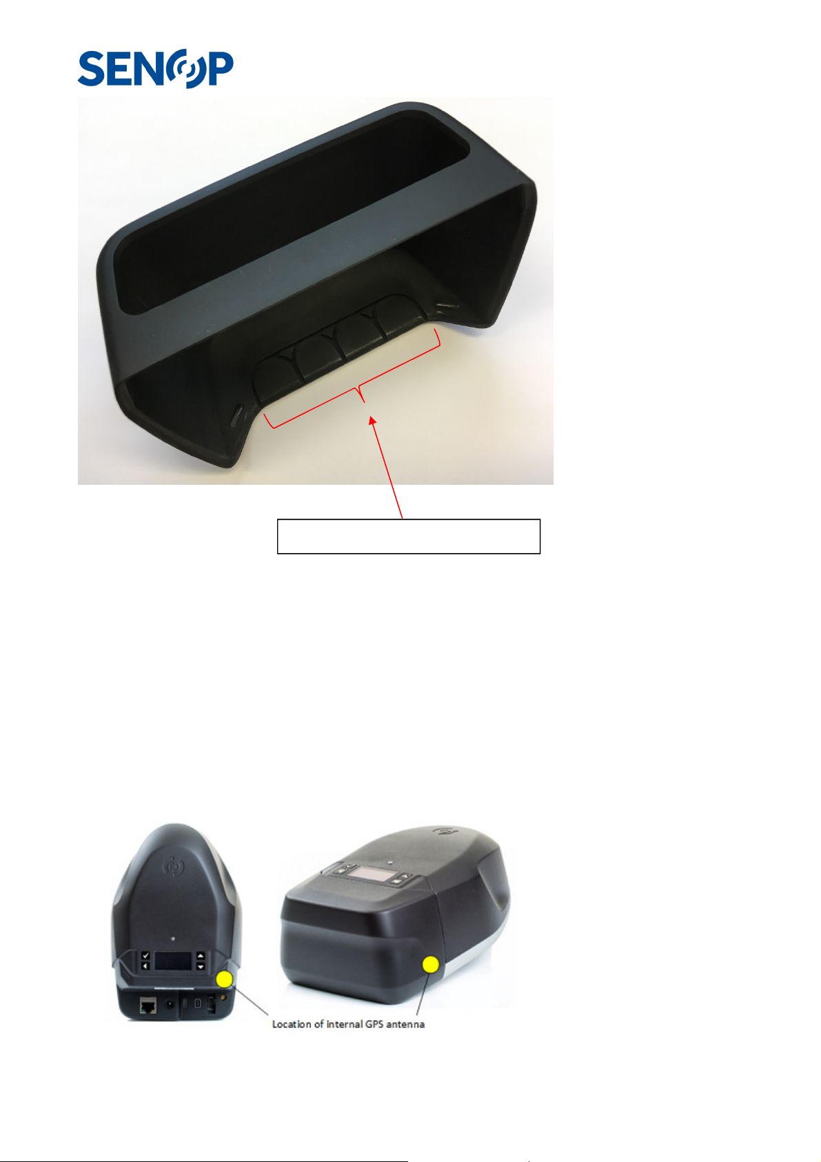
Removable parts for routing cables
.
Electrical connection
Power should be supplied to HSC-2, possible sources are drone itself, gimbal or external battery. There is
power cord supplied with HSC-2 without connector in battery/drone/gimbal end. There is also possibility to
connect AUX connector, USB connector, Ethernet or Mini-DisplayPort if supported by the drone/gimbal.
Power connector type (in cable): Barrel Plug, 2.5mm I.D. x 5.5mm O.D. Positive Center.
GPS in Drone Use
Internal Antenna for Integrated GPS is located so, that is functional in most cases when HSC-2 is attached to
Drones. Location is just front to GPS external antenna connector. Antenna is sensitive to all directions
above base plate
17 25247
Page 18
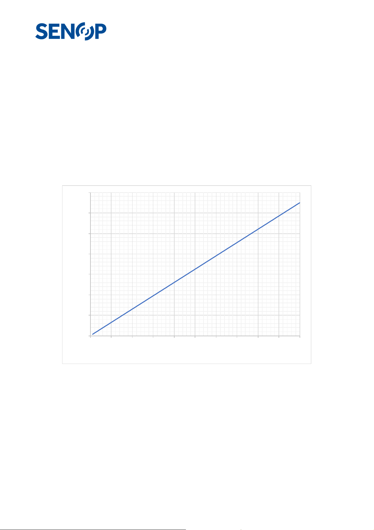
External antenna (not included) thru MMCX connector can be used for example if drone causes too much
interference for GPS. With external antenna also Glonass in possible to use
DJI Matrice 600
Instructions above are compatible for example with DJI Matrice 600 drone & Ronin-MX gimbal with enough
battery capacity.
Imaging from a distance
When the HSC-2 camera is used to image from a great distance, it is useful to consider the affect of the
resolution of the image. The graph below shows the size what one pixel sees at a given imaging distance. For
example, when the image is taken 100m from the target, the image is formed from 65mm x 65 mm resolution.
70
60
50
40
30
Size seen by a pixel, mm
20
10
0
0 10 20 30 40 50 60 70 80 90 100
Imaging dis tance, m
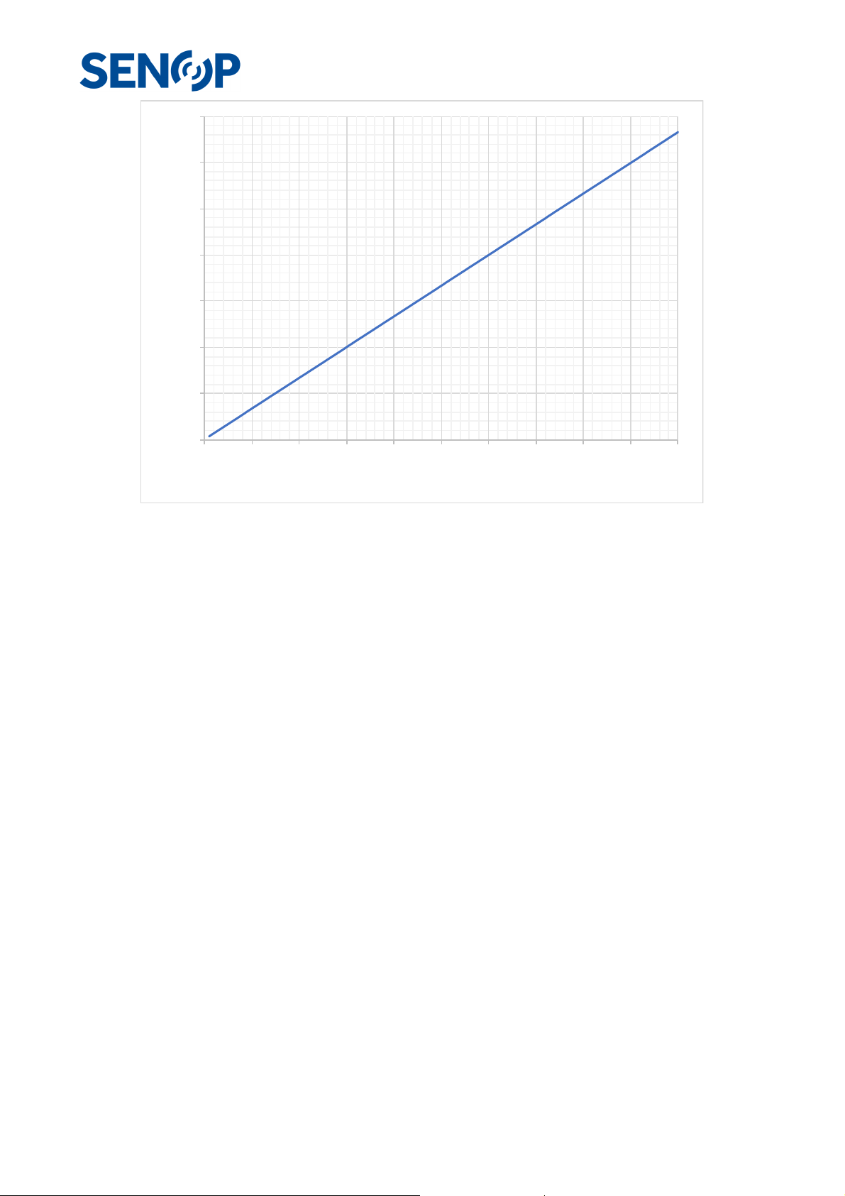
The image below shows the size what the camera can see at a given imaging distance. For example, when
the image is taken 100 m from the target, the camera can see an area of 66 m x 66 m.
18 25247
Page 19
70
60
50
40
30
Size seen by a frame, m
20
10
0
0 10 20 30 40 50 60 70 80 90 100
Imaging distance, m
19 25247
Page 20
Senop HSI Software
Senop Hyperspectral camera HSC-2 can be used as a standalone device but HSI software or some other
compatible software is needed to initialize or control the device.
Senop HSI-2 Software can be used to:
• Viewing live image for camera
• Data browsing
• Data visualization
• Sequence editing
• Script editing
• Device configuration and updating
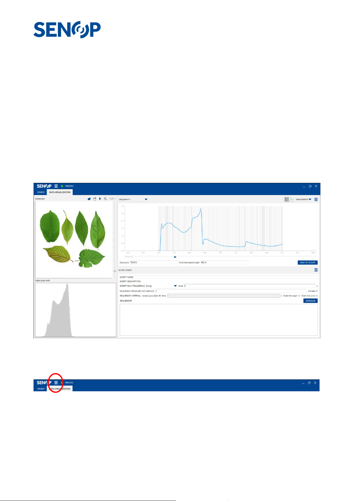
HSI Data Visualization view
In HSI-2 Data Visualization view it is possible to view and analyze either live images or stored data cube. It is
also possible to create and modify scripts.
Main menu
• Save as image: Saves the current image as .png-file
• Save as CSV: Saves the current spectrum as .csv-file.
• About
20 25247
Page 21

Connection Status Indicator
• GREY: Device not connected
• GREEN: Device connected
• RED: Device connected and recording
Data Visualization Toolbar
• Data cube name
o If live stream enabled: Live stream, RGB / WL
o If snapshot taken: Snapshot, script name
o If opened data: Data cube name
• Open data
o Opens file manager
• Snapshot
o Pause / Play
Visualization area
• Live stream: False RGB or Grayscale
• Snapshot: still image, paused from live stream with defined sequence
• Saved data: opened from file
• Picker tool: pick a pixel from the data visualization area to see intensity values of the sequence
wavelengths to the sequence visualization area
Exposure slider
• User can adjust exposure by using exposure slider
Data cube info
• Histogram from either RGB image or selected wavelength.
21 25247
Page 22
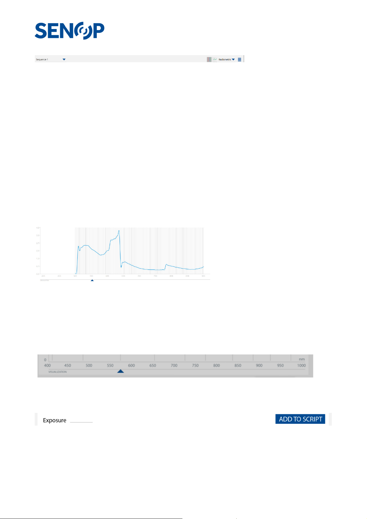
Sequence toolbar
• Sequence toolbar contains the following features and tools.
o Sequence name
o Spectrum visualization method: Dots/point-to-point line/Smoothened
o Data presentation method: Radiometric/Relative in the units of mW/(sr*nm*m2)
o Menu
New: Opens sequence editor for creating new sequence.
Copy: Opens sequence editor with copy of the currently selected sequence for
copying sequence.
Remove: Removes current sequence
Edit: Opens currently selected sequence to the sequence editor for editing
sequence.
Clear all: Clears all sequences from the sequence list except default sequence.
Add to script: Lists sequence to the sequence list of the script
Sequence visualization
• Shows selected sequence: from the opened data, default sequence, sequence defined with
sequence creator or sequence picked from the defined script
Sequence slider
• Select wavelength to visualize it on the data visualization area.
Exposure setting & Add to Script
• Adjust exposure time by typing value directly to the line edit
• Add current sequence to the script by pressing add to script
22 25247
Page 23
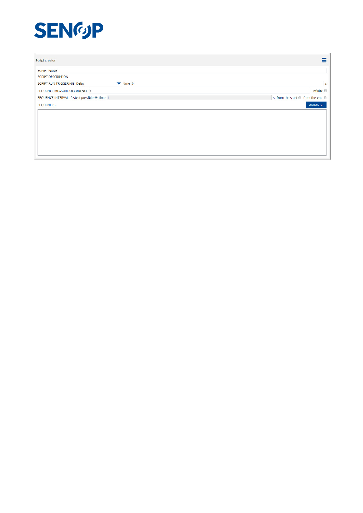
Script Creator
23 25247
Page 24

• Menu
o New: Clear script content and start creating a new script
o Open: Open saved script from computer
o Save as: Save created script to the computer
o Edit Description: Add or edit the description of the script
o Upload: Directly upload script to the device
• Script name: Add name for the script
• Script run triggering: Define triggering method for the script running
o External trigger rising
o External trigger decreasing – Not supported by the software at the moment
o Delay
• Sequence measure occurrence: Number of occurrences or infinite occurrence
• Sequence interval: Interval between two measurements
o Fastest possible
o Time
o From start to start
o From end to start
• Sequences
o Arrange sequences by pressing arrange button
The order of the sequences is the running order in the script
o List of sequences
Sequence name
Exposure time for the sequence
Width settings
o Sequence can be removed by pressing ‘X’ symbol from the end of the sequence list row
24 25247
Page 25
Quick start guide
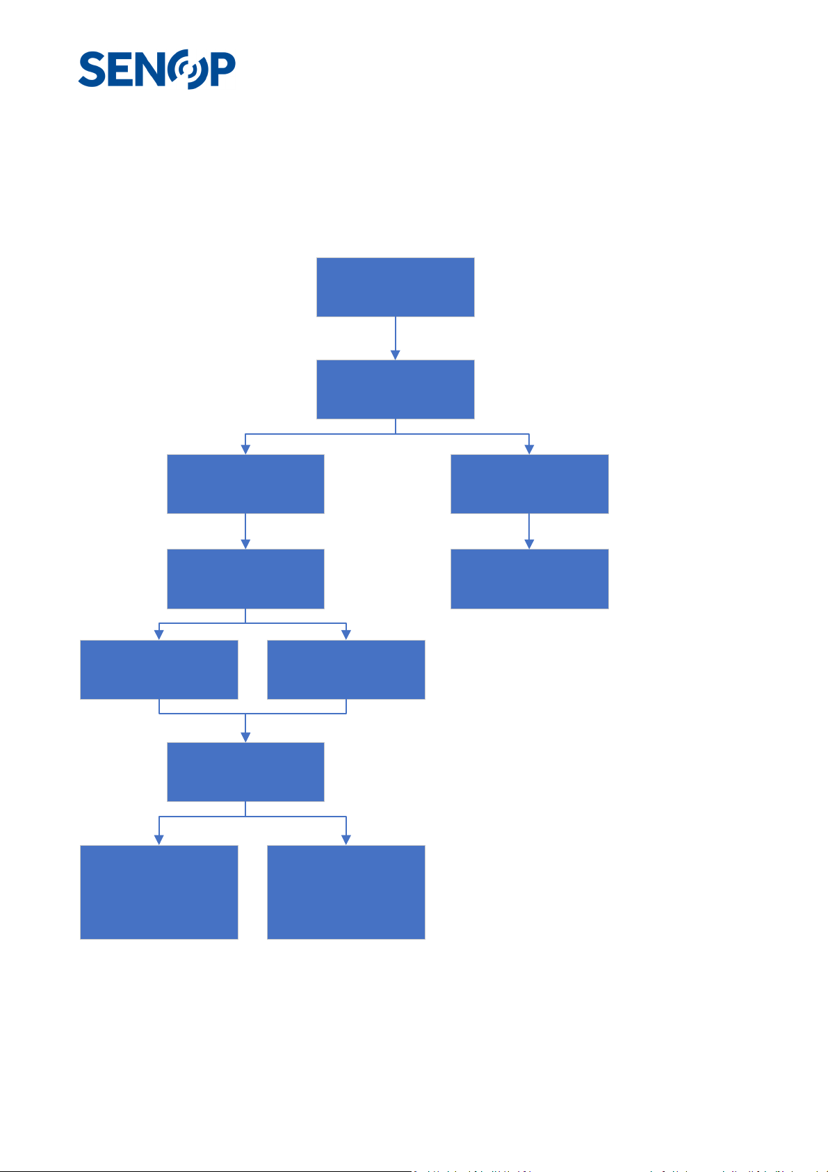
A typical use case scenario is shown on the flow chart image below. All the necessary actions are discussed
in more detail in the text.
Connect the camera to
the HSI-2 software
Create a Sequenc e
Create a measurement
Upload the script to the
HSC-2 camera
Record the script with
the HSI-2 software
Import the data to the PC
using the HSI-2 software
Open the data sequence
on the HSI-2 software
and click anywhere on
the image to see the
spectrum
Script
Take a Snapshot
Click anyw here on the
image to see th e
spectrum
Record the script using
the device UI
Analyze the data using
3rd party software
Connecting to the HSC-2
Power up the HSC-2 device by connecting the DC Voltage cable and connect the Ethernet cable between the
HSC-2 and a PC. Start the Senop HSI-2 Software. On the Device tab, press the + sign. On the opened window,
25 25247
Page 26
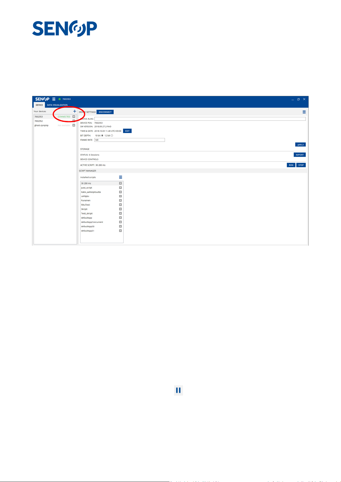
select your device from the Available Devices list and click OK. The device will now be listed as Available on
Your devices list. Click on the device to connect. Wait until the device is connected and the status of the
device is switched to CONNECTED. This may take several minutes. The device alias can be changed from the
DEVICE ALIAS window.
Taking a snapshot using the default Sequence
A snapshot function on the HSI-2 software enables the user to measure one Sequence (i.e. data cube) and
see the spectrum of the imaged scene. Once the camera has taken the data, the spectrum can be seen on
the software by clicking on the image.
Go to the DATA VISUALIZATION sheet. First, you will see an RGB image, which mimics a typical digital camera
image. To see the image at a certain wavelength, uncheck the RGB box and use the slider to navigate to the
desired wavelength. On the top right corner, there is a Visualization window, which shows the selected
wavelengths for the sequence. There is a default sequence shown, which has 13 measurement points, i.e.
frames, between 400 nm – 1000 nm. The exposure value can be changed by adjusting the slider on the right
side of the live image or by setting a value to the Exposure dialog box. Under the live image window, there is
a histogram window, which shows the histogram of the current image. The exposure value should be selected
in such a way, that the image does not saturate to black or white.
To take a snapshot with the default sequence, click the -button. The camera will now take the 13 frames,
as defined in the default sequence, and a status window shows, when the measurement is done. Next, the
spectrum can be acquired by clicking the image at the desired location on the image. The spectrum will be
shown at the Visualization window. The image acquired at certain wavelength can be seen by using the slider
at the desired wavelength on the visualization window. The y-axis of the spectrum can be either Relative or
26 25247
Page 27

Radiometric in the units of mw/(m2*nm*sr). The selection can be done from the drop-down menu at the top
right corner.
The image shown on the top left corner of the software can be saved by clicking the -button on the top
of the window and selecting SAVE AS IMAGE. The spectrum can be saved by using by selecting the SAVE AS
CSV.
Creating and measuring a custom script
Creating a custom sequence
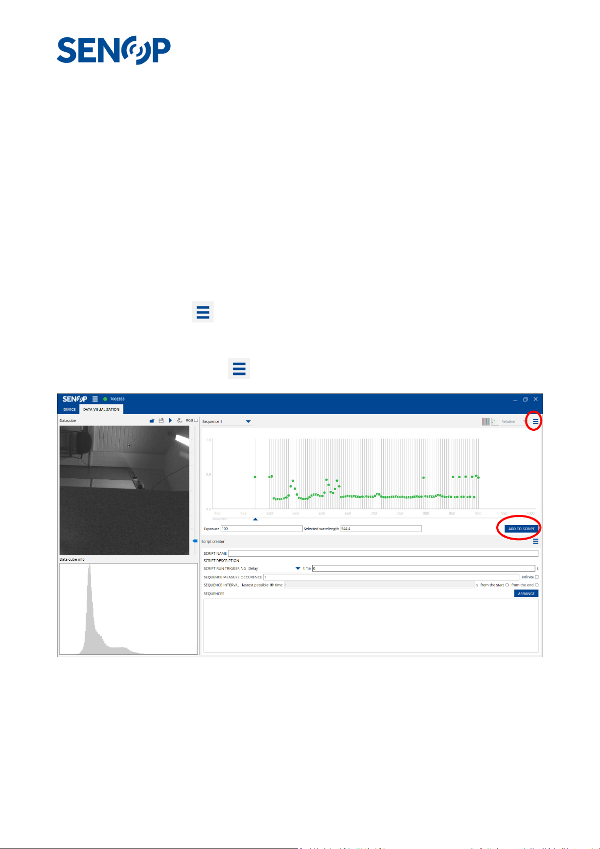
A sequence defines the optical parameters, i.e. the wavelengths to be measured, the bandwidth selection
and integration time (exposure). The sequence parameters are located on the top right corner of the HSI-2
software. To create a new sequence, click the - button from the Sequence window and select New. In
the opened window, select desired wavelength range, number of measurement points, spectral width and
name of the sequence. Add-button adds the measurement points to the list. Click Apply-button to return.
The created sequence can be saved by clicking the -button at the Script Creator line and selecting SAVE
AS. Also, previously saved sequences can be opened by selecting OPEN. The sequences are stored as .json
files. After imaging with a sequence, the name of the sequence is changed to form -1 at the top of the
Sequence window. Further changes to the sequence increase the number. To image with the original
sequence, select the sequence from the drop-down menu.
27 25247
Page 28
Creating a custom script
A Script defines the measurement parameters such as how many times a sequence is to be measured, how
the recording is started etc. All the script parameters are located on the bottom right corner of the HSI-2
software. Once the sequence is created, select the desired Exposure value and then click ADD TO SCRIPT.
Script parameters can then be modified from the Script creator window. Trigger parameters can be adjusted
by using the SCRIPT RUN TRIGGERING. The delay parameter means that the imaging starts after certain time
or if 0 s is selected, the imaging starts immediately after the recording is started. An external trigger can also
be used. If the Rising Edge is selected from the drop-down menu, an external trigger pulse starts the
recording. The use of the trigger is explained in more detail in the Chapter AUX TRIG pin usage principle. The
SEQUENCE MEASURE OCCURRENCE parameter defines how many times the sequence is to be measured
within the script and the SEQUENCE INTERVAL parameter defines what is the time interval between adjacent
measurements. Multiple sequences can be added to a script and their order can be changed by using the
ARRANGE button.
In order to measure with the created script, it needs to be transferred to the HSC-2 camera. After the Script
Name has been created, click -button from the Script Creator window and select UPLOAD. The selected
script will now be transferred to the HSC-2 device. Next, return to the DEVICE sheet. The uploaded script will
now be shown in the SCRIPT MANAGER list. To make the created script as active, select the script from the
list and click the SET ACTIVE from the -list.
Measuring the script using the Senop HSI-2 software
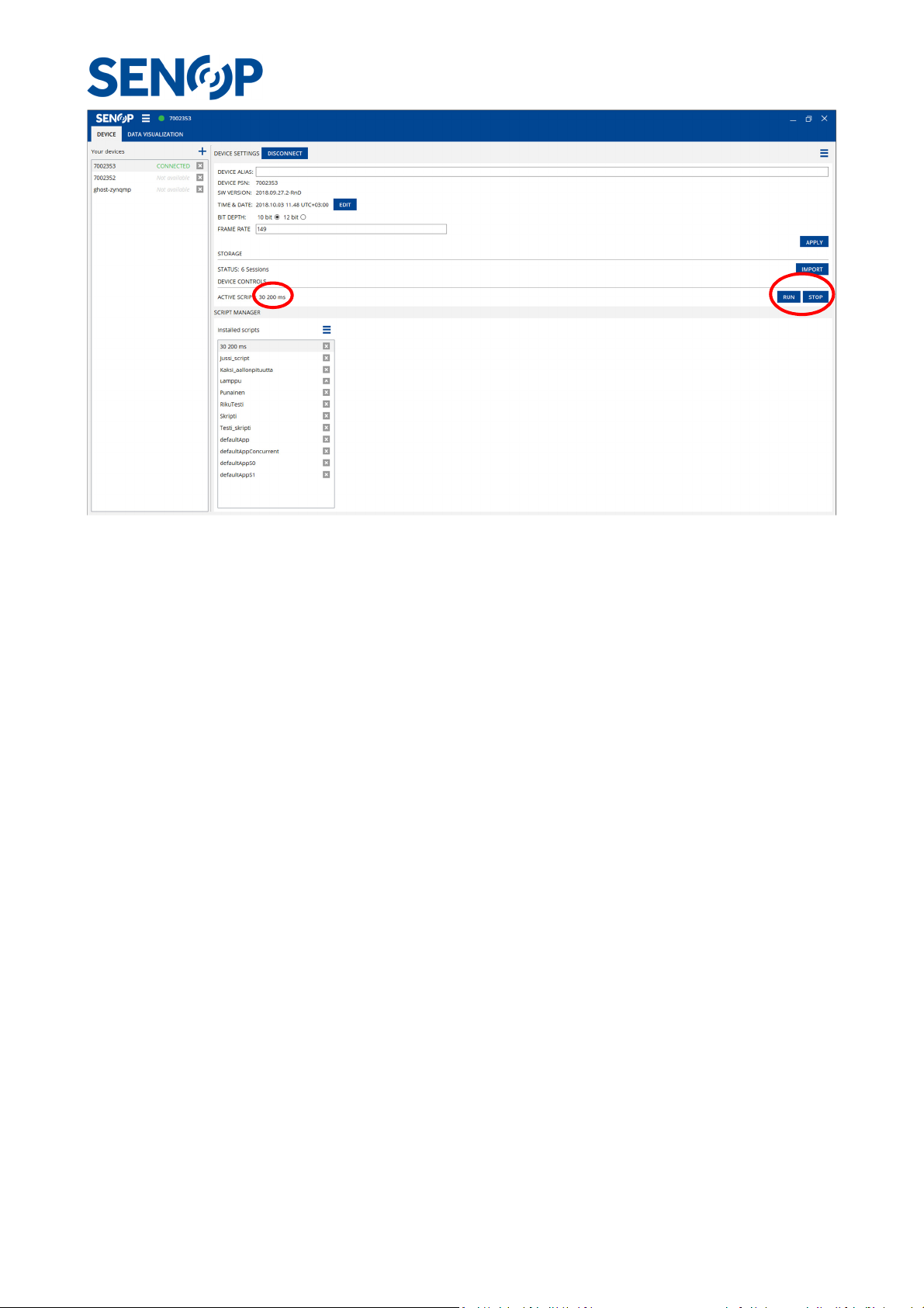
The recording with a script can be done from the DEVICE sheet. Select the desired data format, either 10 bit
or 12 bit and set the frame rate. Press APPLY button. The recording is started by clickin the RUN-button. The
camera will now start to measure the script, and if the script was selected to have infinite amount of
sequence measurements, the measurement can be stopped by clicking the STOP-button.
28 25247
Page 29
Measuring the script using the HSC-2 camera menu
The created scripts can also be measured using the HSC-2 menu and buttons on the device. The Ethernet
cable can be disconnected, and the device only needs an external voltage source. Use the device menu
buttons to navigate to the Settings/Camera and select desired bit depth and frame rate. Return to the main
menu by pressing back-button. Select the Run script and then select the desired script from the list. The
information of the script is shown on the display. To continue, press select-button. Select No to Record
Reference question. The measurement starts by pressing select.
If the selected script has an External trigger selected, the device waits for the trigger pulse for starting the
recording. Once the recording is done, press OK, and back-buttons to navigate to the main menu.
The HSC-2 camera has a Display port, which can be used to transfer the video to and external display. From
the device menu, navigate to the Display port and select Enabled. Connect the HSC-2 camera to an external
display. It is suggested that a cable without any converters is used as some of the video converters are not
supported by the camera. The video is shown at the external display, while a recording with a script is running
on the camera.
Importing the data to the PC
The data taken with the script, is saved into the HSC-2 internal memory. To analyze the data, it needs to be
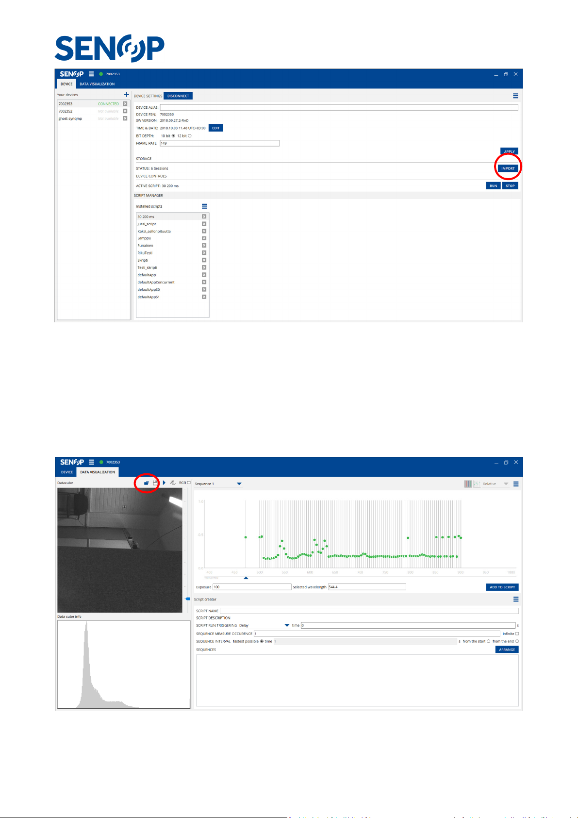
transferred to a PC. The data can be imported with the HSC-2 software by pressing IMPORT-button on the
Device sheet. From the opened window, select the desired script and folder where the data is saved. The
transfer will start by pressing Ok.
29 25247
Page 30
Open the data cube in HSI-2 software
To open the stored data cube, press the open icon at the DATA VISUALIZATION sheet. Select the desired
sequence from the folder and click OK. The data cube opens, and the spectrum can be viewed by clicking
the image.
30 25247
Page 31

Envi header
Example
Description
Envi - Type of the header
description
Senop Hype2.0 Image
Camera name
wavelength
nm Unit of the wavelength
samples
1024
Number of pixels in horizontal
lines
1024
Number of pixels in
vertical
file type
ENVI
Type of the file
interleave
BSQ Data Interleave type, BSQ=Band
byte order
1
Byte order, 1=Most significant
data type
12
Type of data representation,
senop
Sequence
Name of the recorded sequence
bands
5
Number of measurement band
s
acquisition
2019
-03-
22T09:36:31.940629000Z
Time of the acquisition
wavelength
{500.0,600.0,700.0,800.0,900.0}
Measured wavelengths in the
ENVI Data type
The stored data can be analyzed using a 3rd party software. All the sequences in a given script are stored in
the same folder. There is a .png preview images of every frame, the actual data in Envi file format and a
header file, which contains information about the recording parameters.
By default, HSC-2 uses ENVI type image cubes.
• .dat file is ENVI type flat binary file.
• Corresponding Envi Header file (.hdr) is key to open data file.
Header file specifies metadata needed to use .dat file.
• For example: “wavelength = {500.0, 640.0}”
o In this example there is 2 images in Envi hypercube (.dat), first one taken at 500nm
wavelength and second at 640nm.
• There is lot of other information also in header. Like: “Data type = 12” (16-bit unsigned integer),
“byte order = 1” (most significant byte first (MSF)), “data gain values = {0.000542, 0.000557}”
(These values are used to convert integer values in cube to SI unit, different for each image.) etc.
Free programs are available to open ENVI files, as there is libraries to handle ENVI in MatLab or similar
programs.
Below is a list of all the data contained in the header file.
name
units
direction
direction
Sequential
byte first (MSF)
12=Unsigned integer:16 bit
sequence
name
time
31 25247
sequence
Page 32

fwhm
{5
.0,5.0,6.8,7.7,8.0} Full Width at Half Maximum
data gain
{0.000000,0.000137,0.000203,0.000278,0.000387}
Gain values to convert the
geo points
{1.0000,1.0000,62.26495167,26.37
994000}
Geographical coordinates,
senop
{0,1,2,3,4}
Order of t
he requested bands
senop order
{0,0,0,0,0}
Wavelength order of the
senop
{0,55067000,165198000,220266000,110132000}
Acquisition time of the bands
senop sensor
{N/A,N/A,N/A,N/A,N/A}
Used sensor, N/A
senop frame
{0,1,3,4,2}
Order at which the bands are
senop user
{-1,-1,-1,-1,-1} N/A
senop repeat
{-1,-1,-1,-1,-1}
N/A
senop
{50.0,50.0,50.0,50.0,50.0}
Integration time
in ms
used in
senop gps
-
GPS coordinates for each band
senop
{"-0.330096,9.601488,1.556594","
-
Accelerometer values for each
senop
{"-0.009027,
-
0.031365,0.000153","
-
0.009027,
-
Gyroscope values for each band
values at each measured band in
nm
values
sequence
order
timestamp
counter
counter
intensity values to units
mW/(m^2*nm*sr)
pixel_x_coordinate,
pixel_y_coordinate, latitude,
longitude
measured bands, 0=Wide,
1=Normal, 2=Narrow
compared to the first
measurement in nanoseconds
measured
integration
time
acceleration
gyroscope
0.330096,9.601488,1.556594","-
0.317538,9.604478,1.555398","-
0.333086,9.588332,1.563172","-
0.330096,9.601488,1.556594"}
0.031365,0.000153","-0.011628,-
0.031671,0.000612","-0.007650,-
0.031518,0.000459","-0.009027,-
0.031365,0.000153"}
each band
band
32 25247
Page 33
Updating the device software (firmware)
The HSC-2 camera software can be updated using the HSI-2 software. First, you should have received a
software package from an authorized dealer. The software is packaged in -tar.xz file format. The package
should be extracted using for example 7zip software or similar. The xz-package should be extracted first
and then the tar-package. After the extraction, connect the HSC-2 camera to the computer using the
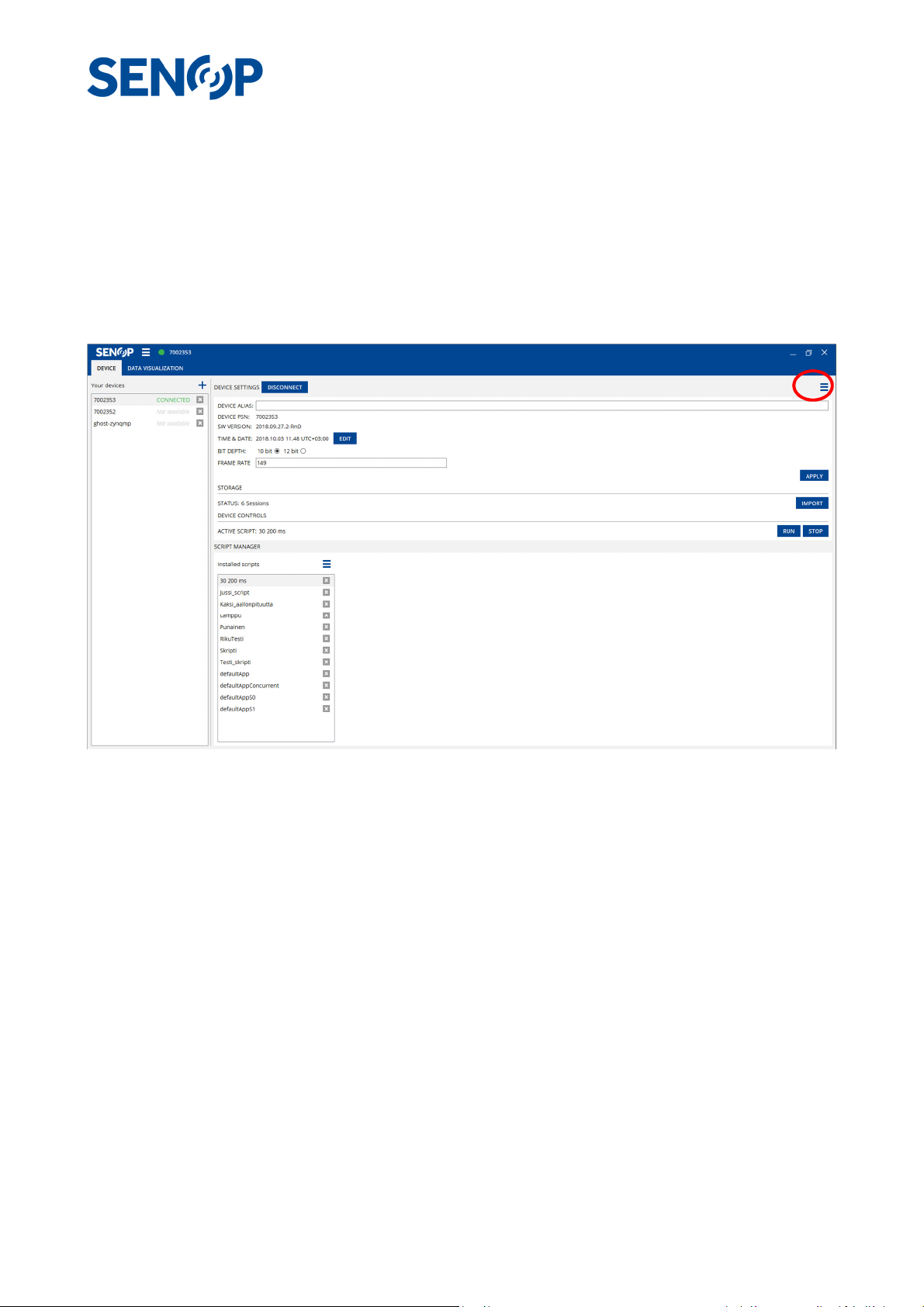
Ethernet cable and connect the camera to the HSI-2 software. From the Device datasheet, select the menu
from the top right corner and click on the FIRMWARE UPDATE. Navigate to the folder, in which the
software was extracted and click OK. After that, the software update starts. DO NOT POWER OFF THE
DEVICE DURING THE UPDATE. When the update has completed successfully, reboot the device.
33 25247
 Loading...