

Page 1
SKM 5200-II
Instruction manual
Page 2

Contents
Contents
Safety instructions ............................................................................................. 2
The SKM 5200-II radio microphone ................................................................ 4
Delivery includes ................................................................................................. 6
Product overview ................................................................................................ 7
Overview of the SKM 5200-II
radio microphone ......................................................................................... 7
Putting the radio microphone into operation .............................................. 9
Inserting, removing and changing the power pack .............................. 9
Changing the microphone head .............................................................. 11
Using the radio microphone ........................................................................... 13
Switching the radio microphone on/off ................................................ 13
Doing a frequency check .......................................................................... 14
The automatic lock mode (autolock function) .................................... 14
Identifying the radio microphone .......................................................... 15
The operating menu ......................................................................................... 16
The buttons ................................................................................................ 16
Overview of the operating menu ........................................................... 17
Working with the operating menu ........................................................ 17
Overview of the operating menu ........................................................... 21
Adjustment tips for the operating menu ................................................... 23
Selecting a channel – “CHAN” ................................................................. 23
Selecting the frequencies to be stored in the
channel bank “VAR” – “TUNE” ............................................................... 23
Entering a name – “NAME” ..................................................................... 25
Adjusting the microphone sensitivity – “ATTEN” ............................... 26
Adjusting the low-cut frequency – “LOWCUT” .................................... 26
Selecting the standard display – “VIEW” ............................................. 26
Loading the factory-preset default settings – “RESET” .................... 27
Activating/deactivating the automatic lock mode – “LOCK” ........... 27
Adjusting the output power – “POWER” .............................................. 28
Displaying the software revision – “SW--REV” ................................... 28
Exiting the operating menu – “EXIT” .................................................... 28
Maintenance and care ..................................................................................... 28
If problems occur .............................................................................................. 29
Accessories ......................................................................................................... 30
Specifications .................................................................................................... 31
Manufacturer Declarations ............................................................................. 33
1
Page 3
Safety instructions
Safety instructions
• Read this instruction manual.
• Keep this instruction manual. Always include this instruction manual
when passing the product on to third parties.
• Heed all warnings and follow all instructions in this instruction
manual.
• Use only a cloth for cleaning the product.
• Do not place the product near any heat sources such as radiators, stoves, or other devices (including amplifiers) that produce heat.
• Only use attachments/accessories specified by Sennheiser.
• Refer all servicing to qualified service personnel.
Servicing is required if the product has been damaged in any way,
liquid has been spilled, objects have fallen inside, the product has been
exposed to rain or moisture, does not operate properly or has been
dropped.
• WARNING: To reduce the risk of short circuits, do not use the product
near water and do not expose it to rain or moisture.
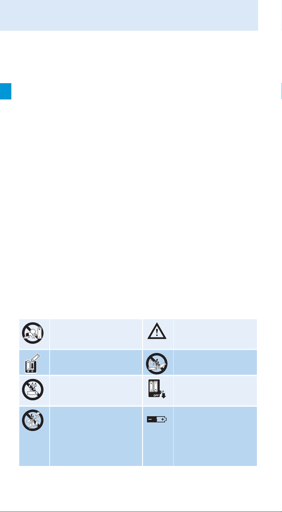
Safety instructions for handling rechargeable batteries
When used properly, rechargeable batteries are a safe and reliable energy
source. However, if abused or misused, rechargeable batteries may leak
and, in extreme cases, may even present an explosion and fire hazard. Please understand that Sennheiser does not accept liability for damage arising from abuse or misuse. Especially observe the following safety instructions:
Keep away from children. Only use rechargeable
batteries recommended
by Sennheiser.
Observe correct polarity. Do not short-circuit.
Do not expose to moisture. Switch rechargeable
battery-powered units
off after use.
Do not get fully charged
but unpacked
rechargeable
batteries mixed up.
2
When not using
rechargeable batteries
for extended periods
of time, charge them
regularly (about every
three months).
Page 4
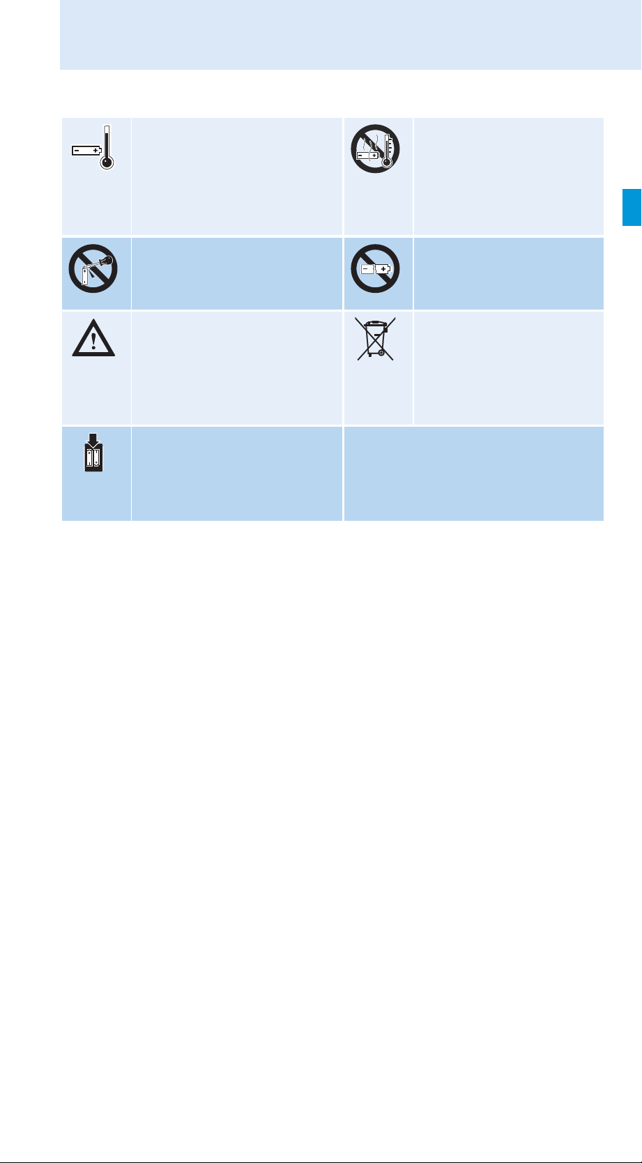
Safety instructions
Only charge rechargeable
batteries at ambient
temperatures between
10°C
and 40°C.
Do not mutilate or
dismantle.
Immediately remove
rechargeable batteries
from
obviously defective units.
Only charge rechargeable
batteries with the
appropriate
Sennheiser chargers.
Do not heat above
70°C/158°F, e.g. do not
expose to sunlight or
throw into a fire.
Do not continue to use
defective rechargeable
batteries.
Dispose of rechargeable
batteries at special
collection points or
return them to your
specialist dealer.
Intended use of the radio microphone
Intended use of the product includes:
• having read these instructions especially the chapter “Important
safety instructions”,
• using the product within the operating conditions and limitations
described in this instruction manual.
“Improper use” means using the product other than as described in this
instruction manual, or under operating conditions which differ from those
described herein.
3
Page 5

The SKM 5200-II radio microphone
The SKM 5200-II radio
microphone
The SKM 5200-II is a professional hand-held radio microphone trans-mitter that is easy to use and is easily adaptable to a wide variety of applications:
• Suitable for all-purpose use, e.g. for reporting, stage and studio applications.
• Rugged housing and intuitive, menu-assisted operation.
• Screw-on microphone heads with different pick-up patterns (omnidirectional, cardioid and super-cardioid) for a wide variety of applications. A super-cardioid dynamic micro-phone head capable of accommodating extremely high sound pressure levels is also available.
• Microphone sensitivity can be adjusted in steps of 1 dB.
• Tunable transmission frequencies ensure high flexibility in varying
transmission situations.
• Can be operated either on rechargeable or standard alkaline batteries
– with LC display (in percent) of charging status on suitable receivers.
• Color-coded identification markers for quick and unambiguous identification.
• Signal-to-noise ratio typ. 110 dB(A)
• Switchable low-cut filter
• Up to 184 MHz switching bandwidth
• Adjustable output power:
10 mW, 10 mW Low Intermodulation mode (LoI), 50 mW.
In Low Intermodulation mode (LoI), the intermodulation performance
is significantly improved
Information on the compander system
plus
This product is equipped with HiDyn
system that reduces RF interference. HiDyn
onal reliability and ensures highest transmission quality.
™, the Sennheiser noise reduction
plus
™ offers extreme operati-
4
Page 6
The SKM 5200-II radio microphone
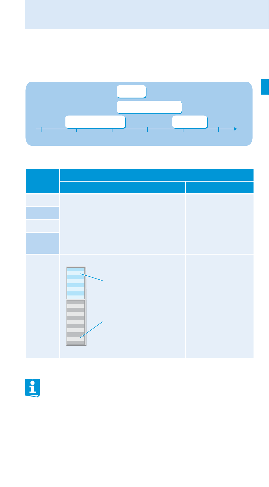
The channel bank system
The transmitter is available in four UHF frequency ranges with up to 184
MHz switching bandwidth:
Range 2 (N-US)
614–697,9 MHz
Range 2 (N)
614–798 MHz
Range 1 (L)
470–638 MHz
400 600 700500 800 900 MHz
Range 3 (P)
776–866 MHz
The transmitter has two frequency banks:
Channel Frequency bank
“FIX” “VAR”
1 The transmission frequencies are
2
factory-preset (see enclosed frequency
table) and cannot be changed.
...
max.
59
Optimized
for maximum
transmission
reliability
Additionally available
nels in Low Intermodulation mode
The transmission
frequencies can be
freely selected
within the
switching
bandwidth.
The factory-preset frequencies within the frequency bank “FIX”
are interference and intermodulation-free.
Set all transmitters of your multi-channel system to different
channels within the frequency bank “FIX”.
5
Page 7

Delivery includes
Variants
• SKM 5200-II (hematite-colored housing)
• SKM 5200 BK-II (black housing)
• SKM 5200 NI-II (nickel-colored housing)
Suitable receivers
• EM 1046 system
• EM 3532, EM 3031, EM 3032
• EK 3041, EK 3241
• EM 3731, EM 3732, EM 3732 COM
• EM 3731-II, EM 3732-II, EM 3732 COM-II
Delivery includes
1 radio microphone transmitter body
(microphone head and power pack to be ordered separately)
1 MZQ 3072 quick release clamp
9 color-coded identification markers
1 instructions for use
1 frequency table
1 RF licensing information sheet
6
Page 8
Product overview
Overview of the SKM 5200-II
radio microphone
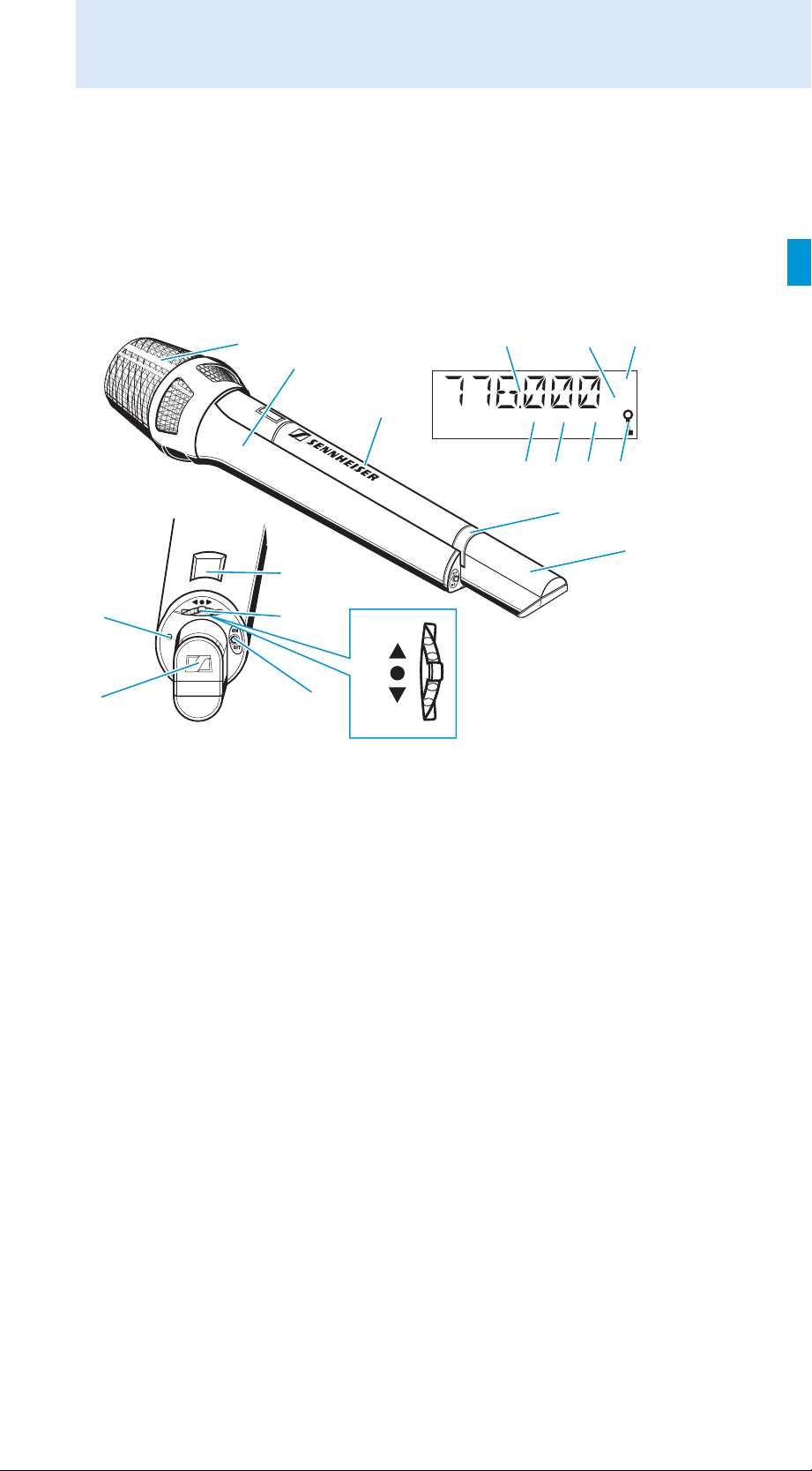
Product overview
Operating controls LC display panel
Screw-on microphone head
(not included in the delivery)
Body of radio microphone
Power pack
(not included in the delivery)
Battery compartment
locking mechanism
Antenna
LC display
Multi-function switch with three
switch positions:
(DOWN), (UP) and (SET)
ON/OFF button (red) with ESC
function (cancel)
Color-coded
identification marker
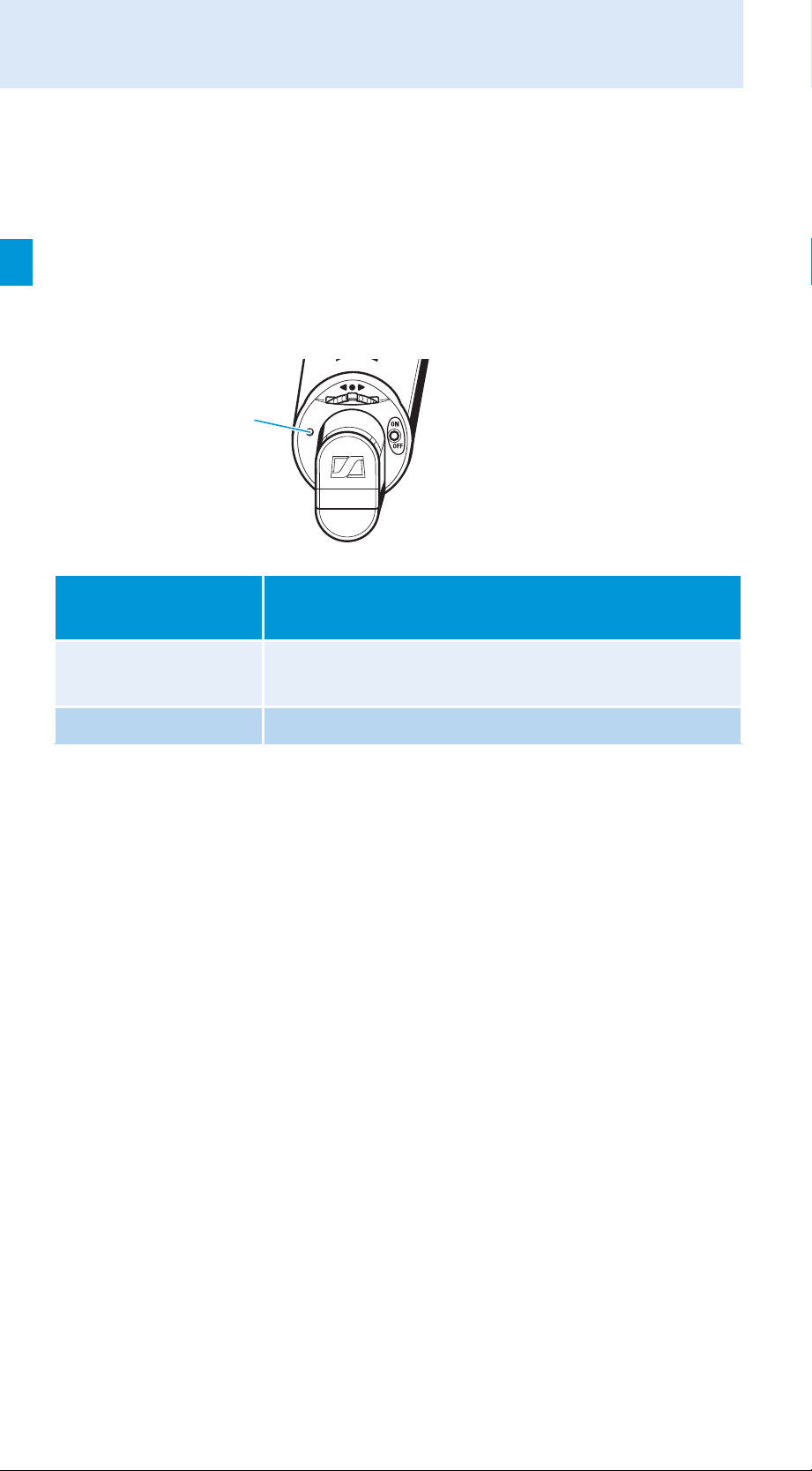
LED ON/LOW BATT: operation
and battery status indication,
green LED
UP
SET
DOWN
Alphanumeric display
Level display for audio signal
“RF” – appears when an
Lock mode icon
“MHz” – appears when the fre-
“dB” – appears when the micro-
“CH” – appears when the chan-
dBCH
“AF”
RF signal is transmitted
quency is displayed
phone sensitivity is displayed
nel number is displayed
RF
AF
MHz
7
Page 9
Product overview
Display backlighting
When the lock mode is deactivated, the display remains backlit for approx.
20 seconds after pressing a button.
Operation and battery status indication
The LED ON/LOW BATT provides information on the current operating
state of the radio microphone:
LED
ON/LOW BATT ...
... lights up normally The radio microphone is switched on and the
... is flashing The power pack is going flat (LOW BATT)!
Meaning
capacity of the power pack is sufficient (ON).
8
Page 10
Putting the radio microphone into operation
Putting the radio microphone into
operation
Inserting, removing and changing the
power pack
For powering the radio microphone, you can either use the Sennheiser
B 5000-2 battery box (1.5 V AA size batteries) or the rechargeable Sennheiser BA 5000-2 battery pack. For regular use, we recommend using the
environmentally friendly rechargeable BA 5000-2 battery pack.
For battery pack operation of the radio microphone, only use the
BA 5000-2 battery pack in order to ensure optimum operational
reliability. Batteries and rechargeable battery cells have different
discharging curves. The radio microphone is able to identify the
BA 5000-2 battery pack and to use its capacity to the full. Individual
rechargeable battery cells in the B 5000-2 battery box will not be
identified as battery packs.
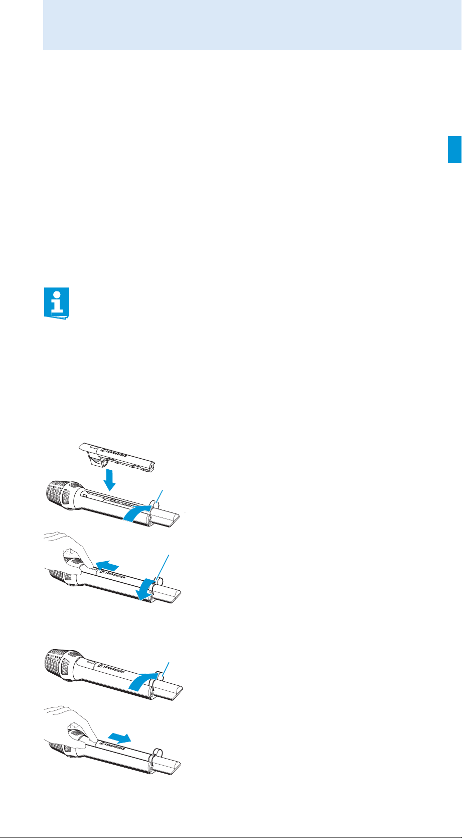
Inserting the power pack
Removing the power pack
Open the locking mechanism by
moving it in the direction of the arrow.
Insert the power pack into the radio micro-
phone.
Push the power pack towards the micro-
phone head.
Close the locking mechanism by
moving it in the direction of the arrow.
Open the locking mechanism by
moving it in the direction of the arrow.
Push the power pack towards the
antenna.
You can now remove the power pack.
9
Page 11
Putting the radio microphone into operation
After you have changed the power pack, the radio microphone continues operating on exactly the same settings as before the change.
Stored settings are retained in memory on switch-off.
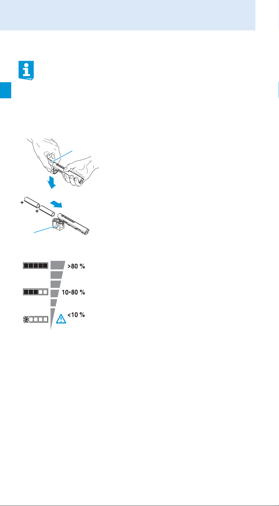
Inserting batteries into the B 5000-2 battery box
To ensure the longest operating time possible, only use alkaline manganese batteries for the B 5000-2 battery box.
To open the battery box, push down the
display section of the battery box .
Insert the batteries. Observe correct pola-
rity when inserting the batteries.
Close the battery box.
LC display shown on the example of the B 5000-2 battery box
• 3-step LC display for remaining battery
capacity.
• If the battery capacity is too low (LOW
BATT), the last segment starts flashing
and the batteries must be changed.
LOW BATT
Recharging the BA 5000-2 battery pack
Before using the BA 5000-2 battery pack for the first time or if you have
not used it for several weeks, you must charge the battery pack completely.
The L 50 charger can charge two BA 5000-2 battery packs simultaneously.
10
Page 12

Putting the radio microphone into operation
Place the appropriate charging adapter
in the charging compartment of the
charger.
Insert the BA 5000-2 battery pack into the
charging adapter .
Charging time: approx. 2.5 hrs with the
L 50 charger (dependent on the residual
charge of the battery pack).
The battery pack is carefully charged using the $U-method. For
further details, please refer to the user manual of the L 50 charger.
LC display shown on the example of the BA 5000-2 battery pack
• 6-step LC display for (remaining) battery
pack capacity.
• Microprocessor-controlled electronics
takes self-discharge of rechargeable cells
into account
• The maximum capacity of is reduced due
LOW BATT
to natural ageing of the cells. The
BA 5000-2 battery pack measures the
maximum capacity and therefore displays
less than 100 % capacity for older cells –
even when they have been fully charged.
Changing the microphone head
To change the microphone head of the SKM 5200-II:
Unscrew the microphone head by turning
it in the direction of the arrow.
11
Page 13

Putting the radio microphone into operation
Pull off the microphone head .
Put on the new microphone head.
Screw tight the microphone head by tur-
ning it against the direction indicated by
the arrow.
Different microphone heads ensure suitability for a wide variety of applications:
Model Type Pick-up pattern SPL
ME 5002 condenser omni 138 dB
ME 5004 condenser cardioid 139 dB
ME 5005 condenser, high feedback
rejection
ME 5005e condenser, high feedback
rejection
ME 5009 condenser wide cardioid 140 dB
MD 5235 dynamic, high feedback
rejection
KK 105 S
(nickelcolored)
KK 105 BK
(black)
KK 104 S
(nickelcolored)
KK 104 BK
(black)
condenser (Neumann) super-cardioid 155 dB
condenser (Neumann) super-cardioid 155 dB
condenser (Neumann) cardioid 153 dB
condenser (Neumann) cardioid 153 dB
super-cardioid 154 dB
super-cardioid 158 dB
cardioid 163 dB
12
Page 14

Using the radio microphone
Using the radio microphone
Switching the radio microphone on/off
To switch the radio microphone on:
Briefly press the ON/OFF button .
The LED ON/LOW BATT lights up and
the standard display is shown on the display panel ; after a short pause, “RF”
appears on the display panel . The LC
display remains backlit for approx. 20
seconds.
Remove the batteries or the battery pack when the radio microphone will not be used for extended periods of time.
The radio microphone can only be switched off when the lock mode
is deactivated (see page 15).
To switch the radio microphone off:
Press the ON/OFF button until “OFF”
appears on the display panel .
The LED ON/LOW BATT and the display
on the display panel go off.
When in the setting mode of the operating menu, the ON/OFF
button will cancel your entry (ESC function).
13
Page 15

Using the radio microphone
MHz
RF
Doing a frequency check
The radio microphone has a frequency check mode that prevents that the
radio microphone transmits on an unwanted frequency after switch-on.
When switching on the device, keep the
ON/OFF button depressed.
The RF signal is deactivated. The current
frequency is displayed on the LC display
panel .
If the displayed frequency is the wanted frequency:
Release the ON/OFF button .
After five seconds the “RF” icon
appears and the radio microphone starts
transmitting.
If you want to select another frequency, proceed as follows:
Release the ON/OFF button .
Within 5 seconds, change to the setting mode of the “CHAN” or
“TUNE” menu.
Change the transmission frequency (see “Adjustment tips for the ope-
rating menu” on page 23.).
The automatic lock mode (autolock
function)
The radio microphone has a lock mode that prevents that the radio microphone is accidentally programmed while operating. When the autolock
function is activated via the “LOCK” menu (see page 27) the lock mode is
automatically activated 10 seconds after pressing the last button and
remains activated.
Prior to this, the lock mode icon flashes
AF
MHz
dBCH
several times on the display.
14
You can deactivate the autolock function either permanently (see
page 27) or temporarily (see page 15).
Page 16

Using the radio microphone
Deactivating the autolock function temporarily
To be able to make changes to the settings via the operating menu, you
must temporarily deactivate the lock mode.
To achieve this, either press the ON/OFF
button or the multi-function switch
(switch position SET).
“LOCK” appears on the display panel .
UP
SET
DOWN
After you have exited the operating menu, the lock mode is automatically
re-activated after 10 seconds. You can also immediately activate the lock
mode by pressing the ON/OFF button briefly.
Slide the multi-function switch to the
position (UP) or ).
“UNLOCK” appears on the display
panel .
Press the multi-function switch (
position
You can now change the settings.
SET).
switch
Identifying the radio microphone
The radio microphone comes with nine interchangeable color-coded identification markers, allowing you to clearly identify each radio microphone.
To remove the identification marker, press
the two snap-in pins together while sliding the identification marker out of the
guide rails.
Put on the new identification marker by
sliding it onto the guide rails.
15
Page 17

The operating menu
The operating menu
The buttons
Button Mode Function
ON/OFF,
ESC
Switched off • Briefly pressing the button:
Switching the radio microphone on
• Keeping the button pressed:
Doing a frequency check
Display mode • Briefly pressing the button
(with activated autolock function):
Immediately activating the lock
mode
• Briefly pressing the button
(with activated lock mode):
Calling up the lock mode for deactivation
• Pressing the button for 3 sec.
(with deactivated lock mode):Switching the radio microphone off
Selection mode Cancelling the entry and returning to
the display mode
Setting mode Cancelling the entry and returning with
the last setting stored to the last
parameter displayed in the display
mode
SET Display mode • With deactivated lock mode:
Changing to the selection mode
• With activated lock mode:
Calling up the lock mode for deactivation
Selection mode Changing to the setting mode of the
selected menu
Setting mode Storing the setting and returning to the
selection mode (“STORED” is displayed)
(UP)/
(DOWN)
16
Display mode Changing to the previous parameter
() or changing to the next
parameter ()
Page 18

Button Mode Function
The operating menu
(UP)/
(DOWN)
Selection mode Changing to the previous menu () or
changing to the next menu ()
Setting mode Increasing () or reducing () the
setting of the selected menu
Overview of the operating menu
:
Menu Function of the menu
“CHAN” Selects a channel
“TUNE” Sets transmission frequencies for the frequency bank
“VAR” (variable bank)
“NAME” Enters a name
“ATTEN” Adjusts the microphone sensitivity
“LOWCUT” Adjusts the bass roll-off frequency
“VIEW” Selects the standard display
“RESET” Loads the factory-preset default settings
“LOCK” Activates/deactivates the autolock function
“POWER” Adjusts the output power
“SW--REV” Displays the current software revision
“EXIT” Exits the operating menu and returns to the standard
display
Working with the operating menu
The operating menu has three modes:
• Display mode
In display mode, you can display the current menu settings one after
the other – even when the lock mode is activated.
• Selection mode
In selection mode, you can select the menu whose setting you want to
change. To change to the selection mode, the lock mode must be deactivated.
• Setting mode
In setting mode, you can change the setting of the selected menu.
17
Page 19

The operating menu
Selection mode
Setting mode
Display mode
SET
190
Hz
120
Hz
STORED
MHz
TUNE
SET
SETSET
LOWCUT
Adjusting the
low-cut-frequency
MHz
FLAT,
120 Hz, 190 Hz
SET/ON
MHz
SET
Current
low-cut-frequency
MHz
Current
low-cut-frequency
By way of example of the “LOWCUT” menu, this section describes how to
use the operating
After switch-on
After switch-on, the standard display is shown on the display panel.
Depending on the setting, the transmission frequency, the channel number or the name of the radio microphone is displayed.
Displaying the menu settings in display mode
In display mode, and with the lock mode activated, you can display the current menu settings one after the other (see “Overview of the operating
menu” on page 21). After a few seconds, the display returns to the standard display. With the lock mode activated, the LC display is not backlit.
18
Page 20

The operating menu
UP
SET
DOWN
Changing to the selection mode
To change from display mode to selection mode, you have to deactivate
the lock mode.
Deactivate the lock mode (see “Deactivating the autolock function
temporarily” on page 15). You can now select the menu whose settings you want to adjust.
Press the multi-function switch (
the menu that was displayed in display mode.
Selecting a menu
UP
Slide the multi-function switch to the
position (UP) or (DOWN)
menu settings
switch repeatedly to the same position, all
menu settings are displayed one after the
other.
Slide the multi-function switch to the
position (UP) or (DOWN).
. If you slide the multi-function
switch position
to display the
SET) to change to
SET
DOWN
Changing to the setting mode of a selected menu
UP
SET
Press the multi-function switch (
position
The name of the selected menu starts flashing.
Press the multi-function switch (
position
mode of the selected menu.
The current setting that can be adjusted flashes on the display.
SET).
SET) to change to the setting
switch
switch
DOWN
Adjusting a setting
Use the multi-function switch to adjust the setting of the selected
menu.
By briefly sliding the multi-function switch to the position
or (DOWN), the display jumps either forwards or backwards to the
next setting.
In the “ATTEN”, “CHAN”, “TUNE” and “NAME” menu and when slid to
(UP)
the position
a “fast search” function, i.e. the display cycles continuously. In the
or (DOWN), the multi-function switch features
(UP)
19
Page 21

The operating menu
“TUNE” menu, the cycling of the display is continuously accelerated.
The “fast search” function allows you to get fast and easily to your
desired setting.
Storing a setting
UP
SET
DOWN
With most menus, new settings become effective immediately without
having to be stored. An exception are the “TUNE” and “CHAN” menus.
With these menus, new settings only become effective after they have
been stored (“STORED” appears on the display panel , indicating that
the setting has been stored).
Exiting the operating menu
Press the multi-function switch (switch
position SET) to permanently store a setting. “STORED” appears on the display
panel , indicating that the setting has
been stored.
The display then returns to the top menu
level.
Select the “EXIT” menu to exit the opera-
ting menu and to return to the standard
display.
When in the operating menu, pressing the
ON/OFF button will cancel your entry
(ESC function) and return you to the standard display with the last stored settings.
20
Page 22

The operating menu
Overview of the operating menu
Deactivate the lock mode before adjusting the settings (see “Deactivating
the autolock function temporarily” on page 15). Pressing the ON/OFF but-
ton will cancel your entry (ESC function) and return you to the display
mode.
Display mode
MHz
SET/
ON
CH
Current
channel bank
SET
MHz
Current frequency
on the selected
channel
Selection mode
RF
CHAN
Changing the
channel bank and
the channel
TUNE
Setting the
frequencies for the
channels of
channel bank "VAR"
SETSET
RF
Setting mode
1 Sec.
VAR. 20
CH
/ :
Channel
VAR.01...20
STORED
Keep SET
pressed
SET
VAR. 20
CH
CH
Current
channel
1 Sek.
776.000
MHz
Current frequency
on the selected
channel
776.000
CH MHz
Transmission frequ.
FIX. 01
/ :
FIX.01...59
SET: Stores the
setting
SET
VAR. 20
CH
CH
Current channel,
that can be
changed
VAR. 01
CH
CH
/ :
VAR.01...20
776.000
MHz
Current frequency
on the selected
channel
1 Sec.
CH
Channel
SET
Current name
IIIIIIII
dB
SET
RF
RF RF
RF RF
AF
NAME
Assigning a name
ATTEN
776.005
frequency in
5-kHz-steps
SET: Stores the
STORED
SET
VOCAL
Current
name
MHz
/ :
Sets the
setting
SET
STORED
RF
776.005
frequency in
5-kHz-steps
SET: Stores the
LOCAL
SET
/ :
Sets the
setting
MHz
SET
RF
21
Page 23

The operating menu
Display mode
dB
RF
RF
AF
SET
SET
Hz
VOCAL
IIIIIIII
Current
modulation
Current
attenuation
Current
low cut frequency
Selection mode
NAME
SET
ATTEN
Adjusting the
attenuation
LOWCUT
Adjusting the
low-cut-frequency
VIEW
Selecting the
standard display
Setting mode
RF
SET
RF RF RF
SET
SET
RF
12
dB
Current
attenuation
STORED
120
Current
low-cut-frequency
Current
standard display
RFRF RF
Hz
STORED
RF
FREQ
STORED
13
/ :
Adjusts the
attenuation in 1-dBsteps, -40...0 dB
190
FLAT,
120 Hz, 190 Hz
SET
NAME
CH
/ :
FREQ,
CHAN, NAME
SET
dB
SET
Hz
RF
CHAN
CH
/ :
FREQ,
NAME, CHAN
RF
Current output
power
VAR. 01
dB
SET
RF
RESET
Loading the
factory-preset
default settings
LOCK
Setting the
autoloc-function
POWER
Adjusting the
output power
SW--REV
Displaying the
software revision
EXIT
RF
RF
RF
RF
RF
SET
RST. NO
Security check
RF
SET
SET
LOC.
Current
Setting
RF RF
ON
STORED
SET
PWR.LO PWR.HI
Current setting
STORED
SET
NET.200
current
software revision
SET
RST. OK
/ :
"reset" = OK:
SET
laods factory-preset
default settings,
standard display
appears
"reset" = NO :
SET:
RF
OK, NO
radio microphone
:
Reset is cancelled
LOC. OFF
LOC.ON
/ :
LOC.OFF
SET
PWR.LoI
PWR.LO
PWR.LoI
PWR.HI
PWR.LO
22
MHz
Exiting the
operating menue
Page 24

Adjustment tips for the operating menu
Adjustment tips for the operating
menu
When setting frequencies on the bodypack transmitter, please
observe the following:
Make sure that the desired frequencies are listed in the enc-
losed frequency table.
Make sure that the desired frequencies are approved and legal
in your country and, if necessary, apply for an operating
license.
Selecting a channel – “CHAN”
Via the “CHAN” menu, you can switch between the channels in the channel
banks “FIX” and “VAR“. The radio microphone is not transmitting while
this adjustment is being made.
When changing to the setting mode of the “CHAN” menu, the current
channel number appears on the display. After approx. 1 second, the currently assigned frequency is displayed.
1 sec.
CH
To select a different channel, slide the multi-function switch to the
position (UP) or (DOWN). The new channel number appears on
the display panel for approx. 1 second and then the currently assigned frequency is displayed.
Only after the new setting has been stored (“STORED” has appeared
on the display panel ) does the transmitter operate on the transmission frequency of the new channel.
CH
CH
MHz
Selecting the frequencies to be stored in
the channel bank “VAR” – “TUNE”
Via the “TUNE” menu, you can freely select the frequencies to be stored in
the channel bank “VAR” (variable bank). The radio microphone is not
transmitting while this adjustment is being made.
23
Page 25

Adjustment tips for the operating menu
CH
When you have selected the channel bank “FIX” and then select the
“TUNE” menu, the radio microphone automatically switches to
channel 01 of the channel bank “VAR” and “VAR” briefly appears on
the display panel .
The transmission frequencies are tunable in 5-kHz steps within a switching
bandwidth of 184 MHz max.
When operating a multi-channel system, make sure to only use
intermodulation-free frequencies.
There are two options for setting the frequencies:
• You can set a new frequency for the selected channel:
UP
In the selection mode of the “TUNE” menu,
press the multi-function switch (switch
SET
position SET). The current channel number
appears on the display and then the currently assigned frequency is displayed.
DOWN
CH
Change the frequency by sliding the multi-
function switch to the position (UP) or
CH
• You can change to a different channel and set a new frequency for the
new channel:
UP
SET
DOWN
MHz
MHz
(DOWN).
Store your setting.
Press the multi-function switch for a longer
time (switch position SET). The current
channel flashes on the display.
Select a new channel by sliding the multi-
function switch to the position (UP) or
(DOWN).
24
CH
CH
Confirm your selection by pressing the multi-
function switch (switch position SET).
RF
Page 26

Adjustment tips for the operating menu
MHz
The current frequency of the selected chan-
nel is displayed.
CH
MHz
Change the frequency by sliding the multifunction switch to the position (UP) or
(DOWN).
Store your setting.
Entering a name – “NAME”
Via the “NAME” menu, you can enter a freely selectable name for the radio
microphone. This name can be displayed on the standard display and can
consist of up to six characters such as:
• letters (without pronounciation marks),
• numbers from 0 to 9,
• special characters and spaces.
After you have changed to the setting mode of the “NAME” menu, the first
segment starts flashing on the display.
UP
Slide the multi-function switch to the
position (UP) or (DOWN) to select a
SET
character.
(By sliding the switch only once, the next or
the previous character is displayed. If you
DOWN
keep the switch slid, the characters change in
quick succession.)
Press the multi-function switch (switch
position SET) to change to the next segment.
Have you entered the name completely?
Press the multi-function switch (switch
position SET) to store your setting.
“STORED” appears on the display panel .
25
Page 27

Adjustment tips for the operating menu
Adjusting the microphone sensitivity –
“ATTEN”
Via the “ATTEN” menu, you can adjust the radio microphone’s sensitivity
by changing its input attenuation.
RF
AF
dB
The bargraph has a resolution of approx. 3 dB per segment with a
display range of 45 dB.
The input attenuation is correctly adjusted
when the level display for audio signal “AF”
shows full deflection only during the loudest passages. The input attenuation can be
adjusted in 1-dB steps from – 40 dB to 0 dB.
Adjusting the low-cut frequency –
“LOWCUT”
To reduce unwanted low-frequency noise such as engine, wind and rumble
noise, you can activate a low-cut filter. The low-cut frequency can be set to
190 Hz or 120 Hz.
If you do not want to reduce low-frequency signal portions, select the setting “FLAT”.
Selecting the standard display – “VIEW”
Via the “VIEW” menu, you can select one of the following standard displays:
RF
CH
CH
Transmission frequency
“FREQ”
The selected standard display is shown
• after switch-on,
• after the menu settings have been displayed in display mode.
26
MHz
Channel
“CHAN”
CH
RF
Name
“NAME”
RF
Page 28

Adjustment tips for the operating menu
Loading the factory-preset default
settings – “RESET”
Via the “RESET” menu, you can load the factory-preset default settings.
After the reset, the standard display is shown on the display panel .
Function Setting
Low-cut frequency “FLAT”
Microphone sensitivity “–20 dB“
Name “5200“
Standard display frequency
Autolock function deactivated
Channel “FIX 01“
Output power “PWR.HI”
Frequencies in the channel bank “VAR ” are reset
Activating/deactivating the automatic
lock mode – “LOCK”
The radio microphone has an autolock function (automatic lock mode)
that can be activated or deactivated via the “LOCK” menu. When the autolock function is activated,
10 seconds after pressing the last button. The lock mode protects the radio
microphone from accidental programming. For daily use, we would recommend activating the autolock function.
UP
SET
DOWN
RF
the lock mode is automatically activated
In the selection mode of the “Lock” menu,
press the multi-function switch (switch
position SET).
The current setting of the autolock function
is displayed.
Change the setting by sliding the multi-func-
tion switch to the position (UP) or
(DOWN).
RF
Select “LOC.ON” to activate the autolock
function or select “LOC.OFF” to deactivate
the autolock function.
Store your setting.
27
Page 29

Maintenance and care
Adjusting the output power – “POWER”
The radio microphone features switchable output power. With reduced
output power, the operating time increases.
In addition, you can also adjust the radio microphone to “Low Intermodulation mode” (“LoI”). By so doing, the radio microphone’s intermodulation
performance is significantly improved, especially in multi-channel operation. In “Low Intermodulation mode”, the output power is reduced to
10 mW; the operating time will be about the same as using an output
power of 50 mW.
Displaying the software revision – “SW--
REV”
You can display the current software revision of the radio microphone by
calling up the “SW--REV” menu item.
Exiting the operating menu – “EXIT”
Via the “EXIT” menu, you can exit the operating menu and return to the
standard display.
When in the operating menu, briefly pressing the ON/OFF button will
cancel your entry (ESC function) and return you to the standard display
without saving any changes.
Maintenance and care
CAUTION! Liquids can damage the electronics of the radio micro-
phone!
Liquids entering the housing of the device can cause a
short-circuit and damage the electronics.
Keep all liquids away from the radio microphone.
Use a cloth to clean the radio microphone from time to time.
Do not use any solvents or cleansing agents.
28
Page 30

If problems occur
If problems occur
Problem Possible cause Possible solution
No operation
indication
Transmitter
cannot be
switched off/
Settings cannot
be changed
Receiver:
No RF signal
Weak signal Antenna signal is
Batteries are flat or
inserted incorrectly,
battery pack is flat
Lock mode is activated Deactivate the lock mode
Transmitter and receiver
are not on the same
channel
Transmitter is out of
range
attenuated
Replace the batteries or
check if they are inserted
correctly or recharge the
battery pack
(see “Deactivating the
autolock function
temporarily” on page 15)
Set transmitter and
receiver to the same
channel
Check the squelch
threshold setting
or reduce the distance
between receiving
antenna and transmitter
Do not clasp the antenna
section
Audio signal has
a high level of
background
noise
Audio signal is
distorted
If problems occur that are not listed in the above table or if the problems
cannot be solved with the proposed solutions, please contact your local
Sennheiser agent for assistance.
To find a Sennheiser partner in your country, search at www.sennheiser.com
under “Service & Support”.
Transmitter’s input
attenuation is adjusted
too high
Receiver’s output level is
adjusted too low
Transmitter’s input
attenuation is adjusted
too low
Receiver’s output level is
adjusted too high
see “Adjusting the
microphone sensitivity –
“ATTEN”” on page 26
Increase the line output
level
see “Adjusting the
microphone sensitivity –
“ATTEN”” on page 26
Reduce the line output
level
29
Page 31

Accessories
Accessories
003763 ME 5009 microphone head
003760 ME 5005 microphone head
005249 ME 5005e microphone head
003762 ME 5004 microphone head
003761 ME 5002 microphone head
003823 MD 5005 microphone head
008474 Neumann KK 105 S microphone head
008476 Neumann KK 105 S-BK microphone head
008533 Neumann KK 104 S-BK microphone head
008534 Neumann KK 104 S microphone head
005273 B 5000-2 battery box
005274 BA 5000-2 battery pack incl. charging adapter for the L 50
charger
003554 L 50 charger (for BA 5000-2 battery pack)
051662 Charging adapter for L 50 charger
003824 MZW 5000-ANT windshield, anthracite,
without identification ring
003825 MZW 5000-BL windshield with blue identification ring
003826 MZW 5000-GE windshield with yellow identification ring
003827 MZW 5000-GN windshield with green identification ring
003828 MZW 5000-RT windshield with red identification ring
003829 MZW 5000-WS windshield with white identification ring
512888 9 color-coded identification markers
30
Page 32

Specifications
Specifications
Modulation wideband FM
Frequency range range 1 (L): 470 to 638 MHz
range 2 614 to 798 MHz/
(N/N-US): 614 to 697.9 MHz
range 3 (P): 776 to 866 MHz
Switching bandwidth up to 184 MHz
Transmission frequencies
RF output power switchable,
Frequency stability p 10 kHz within the specified
Nominal/peak deviation p40 kHz/p56 kHz FM
Signal-to-noise ratio typ. 110 dB (A)
THD (at 1 kHz, nom. deviation) 0.5 %
AF frequency response 60–20,000 Hz
Noise reductions system Sennheiser HiDyn plus™
frequency bank
59 factory-preset frequencies
frequency
freely selectable frequencies
(frequencies tuneable in steps of
5 kHz)
typ.: 50 mW (PWR.Hi)
10 mW (PWR.LO)
10 mW (PWR.LoI)
temperature range
“FIX” with up to
bank “VAR” with 20
rms
Low-cut frequency (–3 dB) adjustable (flat, 120 Hz, 190 Hz)
Sensitivity adjustable in steps of 1 dB
from –40 to 0 dB
Power consumption
(without LC display illumination)
Operating time with B 5000-2:
PWR.LO: approx. 140 mA
(10 mW) at 2.4 V
PWR.HI: approx. 195 mA
(50 mW) at 2.4 V
PWR.LoI: approx. 195 mA
(10 mW) at 2.4 V
PWR.LO: approx. 13 hrs
PWR.HI: approx. 7 hrs 30 min
PWR.LoI: approx. 7 hrs 30 min
31
Page 33

Specifications
with BA 5000-2:
PWR.LO: approx. 12 hrs 40 min
PWR.HI: approx. 7 hrs 20 min
PWR.LoI: approx. 7 hrs 20 min
Dimensions length: 200 mm (without
microphone head), 35.5 mm
Weight approx. 300 g incl. BA 5000-2,
without microphone head
Operating conditions
Ambient temperature –10 °C to +55 °C
Relative humidity max. 90 % (non condensing)
Power supply B 5000-2 battery box (1.5 V AA
size batteries) or
rechargeable Sennheiser
BA 5000-2 battery pack
Storage and transport conditions
Ambient temperature –25 °C to +70 °C
Relative humidity max. 90 %
Shock test shock test according to IEC 68 or
EN 60068, T2-27
In compliance with
Europe EMC EN 301489-1/-9
Radio EN 300422-1/-2
Safety EN 60065
EN 62311 (SAR)
Approved by
Canada Industry Canada RSS-123
IC: 2099A-SKM5200A2
limited to 698 MHz
USA FCC-Part 74
FCC ID: DMOSKM5200A2
limited to 698 MHz
32
Page 34

Manufacturer Declarations
Manufacturer Declarations
Warranty
Sennheiser electronic GmbH & Co. KG gives a warranty of 24 months on this
product.
For the current warranty conditions, please visit our web site at
www.sennheiser.com or contact your Sennheiser partner.
In compliance with
• RoHS Directive (2002/95/EC)
• Battery Directive (2006/66/CE)
The supplied batteries or rechargeable batteries can be recycled. Please dispose of them as special waste or return them
to your specialist dealer. In order to protect the environment,
only dispose of exhausted batteries.
CE Declaration of Conformity
•
•R&TTE Directive
Statements regarding FCC and Industry Canada
This device complies with Part 15 of the FCC Rules and with RSS-210 of
Industry Canada. Operation is subject to the following two conditions: (1)
this device may not cause harmful interference, and (2) this device must
accept any interference received, including interference that may cause
undesired operation.
This equipment has been tested and found to comply with the limits for a
Class B digital device, pursuant to Part 15 of the FCC Rules. These limits are
designed to provide reasonable protection against harmful interference in
a residential installation. This equipment generates, uses and can radiate
radio frequency energy and, if not installed and used in accordance with
the instructions, may cause harmful interference to radio communications.
However, there is no guarantee that interference will not occur in a particular installation. If this equipment does cause harmful interference to
radio or television reception, which can be determined by turning the
equipment off and on, the user is encouraged to try to correct the interference by one or more of the following measures:
0682
(1999/5/EC)
The declarations are available at www.sennheiser.com.
Before putting the device into operation, please observe the respective country-specific regulations.
• Reorient or relocate the receiving antenna.
• Increase the separation between the equipment and receiver.
33
Page 35

Manufacturer Declarations
• Connect the equipment into an outlet on a circuit different from that
to which the receiver is connected.
• Consult the dealer or an experienced radio/TV technician for help.
This class B digital device complies with the Canadian ICES-003.
Changes or modifications made to this equipment not expressly approved
by Sennheiser electronic Corp. may void the FCC authorization to operate
this equipment.
Before putting the device into operation, please observe the respective
country-specific regulations!
34
Page 36

Sennheiser electronic GmbH & Co. KG
Am Labor 1, 30900 Wedemark, Germany
www.sennheiser.com
Publ. 03/10
532899/A01
 Loading...