

Page 1
freeport_514013_0808_Sp5.book Seite 1 Freitag, 29. August 2008 12:08 12
Bedienungsanleitung
Instructions for use
Notice d‘emploi
Istruzioni per l’uso
Instrucciones de uso
Page 2

freeport_514013_0808_Sp5.book Seite 2 Freitag, 29. August 2008 12:08 12
Page 3
freeport_514013_0808_Sp5.book Seite 1 Freitag, 29. August 2008 12:08 12
Deutsch
English
Français
Italiano
Español
Page 4

freeport_514013_0808_Sp5.book Seite 2 Freitag, 29. August 2008 12:08 12
Page 5
freeport_514013_0808_Sp5.book Seite 1 Freitag, 29. August 2008 12:08 12
Inhalt
Wichtige Sicherheitshinweise ....................................................... 2
Die freePORT Sets ............................................................................ 3
Lieferumfang der Sets .............................................................. 4
Empfänger EM 1 ............................................................................... 4
Taschensender SK 2 ......................................................................... 6
Funkmikrofon SKM 3 ....................................................................... 8
Das System optimieren .................................................................. 9
Pflege und Wartung ......................................................................10
Wenn Störungen auftreten ......................................................11
Zubehör und Varianten ................................................................11
Technische Daten der Sets ...........................................................12
Steckerbelegung ......................................................................13
Herstellererklärungen ...................................................................14
Garantie .....................................................................................14
EG-Konformitätserklärung .....................................................14
Akkus und Batterien ...............................................................14
WEEE-Erklärung .......................................................................14
Sie haben die richtige Wahl getroffen!
Diese Sennheiser-Produkte werden Sie lange Jahre durch Zuverlässigkeit, Wirtschaftlichkeit und einfache Bedienung überzeugen. Dafür
garantiert Sennheiser mit seinem guten Namen und seiner in mehr als
60 Jahren erworbenen Kompetenz als Hersteller hochwertiger elektroakustischer Produkte.
Nehmen Sie sich nun ein paar Minuten Zeit, um diese Anleitung zu
lesen. Wir möchten, dass Sie einfach und schnell in den Genuss dieser
Technik kommen.
1
Page 6
freeport_514013_0808_Sp5.book Seite 2 Freitag, 29. August 2008 12:08 12
Wichtige Sicherheitshinweise
y Lesen Sie diese Bedienungsanleitung.
y Bewahren Sie diese Bedienungsanleitung auf. Geben Sie das Gerät
und das Steckernetzteil an andere Nutzer stets zusammen mit dieser
Bedienungsanleitung weiter.
y Beachten Sie alle Warnhinweise, befolgen Sie alle Anweisungen in
dieser Bedienungsanleitung.
y Reinigen Sie das Gerät und das Steckernetzteil nur mit einem trocke-
nen Tuch.
y Lassen Sie alle Wartungsarbeiten von qualifiziertem Wartungsperso-
nal durchführen. Wartungsarbeiten müssen durchgeführt werden,
wenn das Gerät oder das Steckernetzteil auf irgendeine Weise
beschädigt wurde, wenn Flüssigkeiten oder Objekte in das Gerät oder
das Steckernetzteil eingedrungen sind oder sie Regen ausgesetzt
waren, sie nicht fehlerfrei funktionieren oder fallen gelassen wurden.
y WARNUNG: Setzen Sie das Gerät und das Steckernetzteil weder
Regen noch Feuchtigkeit aus. Andernfalls besteht die Gefahr eines
Brandes oder Stromschlages. Stellen Sie keine mit Flüssigkeiten
gefüllten Gefäße auf das Gerät.
y Verwenden Sie ausschließlich das mitgelieferte Steckernetzteil.
y Ziehen Sie das Steckernetzteil aus der Steckdose,
– um das Gerät vom Netz zu trennen,
– wenn Gewitter auftreten oder das Gerät über einen längeren Zeit-
raum nicht verwendet wird.
y Betreiben Sie das Steckernetzteil ausschließlich an Stromquellenty-
pen, die den Angaben im Kapitel „Technische Daten der Sets“
(Seite 12) entsprechen.
y Achten Sie immer darauf, dass das Steckernetzteil
– in ordnungsgemäßem Zustand und leicht zugänglich ist,
– fest in der Steckdose steckt,
– nur im zulässigen Temperaturbereich
betrieben wird,
– nicht abgedeckt oder längerer Sonnenbestrahlung ausgesetzt
wird, um eine Überhitzung zu verhindern (siehe “Technische Daten
der Sets” auf Seite 12).
y Blockieren Sie keine Lüftungsöffnungen. Stellen Sie das Gerät und
das Steckernetzteil nach den Anweisungen in dieser Bedienungsanleitung auf.
y Stellen Sie die das Gerät und das Steckernetzteil nicht in der Nähe von
Wärmequellen auf.
y Verwenden Sie nur Zusatzgeräte/Zubehörteile, die Sennheiser emp-
fiehlt.
2
Page 7

freeport_514013_0808_Sp5.book Seite 3 Freitag, 29. August 2008 12:08 12
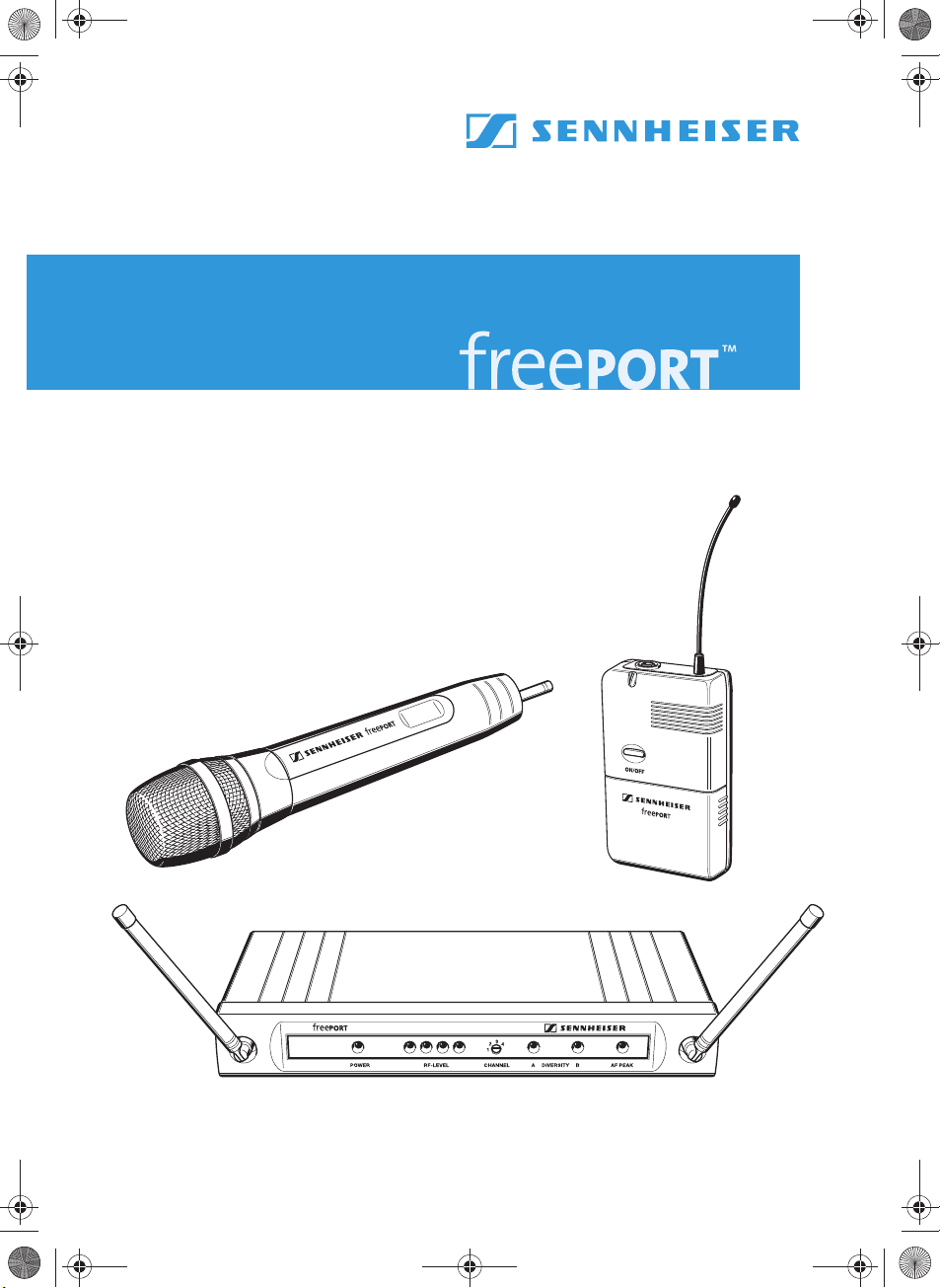
Die freePORT Sets
Optimiert für den jeweiligen Anwendungsbereich erhalten Sie die
freePORT Sets in drei Set-Varianten.
y Presentation Set
Das Presentation Set ist ideal für den Einsatz bei der Moderation und
bei Vorträgen. Das Ansteck-Mikrofon ME 2 kann nahezu unsichtbar
getragen werden.
y Instrument Set
Musikinstrumente mit einer 6,3-mm-Klinkenbuchse (z. B. Gitarren)
können Sie mit diesem Set drahtlos betreiben.
y Vocal Set
Das Vocal Set können Sie unkompliziert zur Übertragung von Gesang
und Sprache einsetzen.
Die Sender und Empfänger der freePORT Sets verfügen über vier voreingestellte Preset-Frequenzen für die direkte Kanalwahl und können nach
dem Einschalten sofort in Betrieb gehen.
Sie erhalten die freePORT Sets in drei Frequenzvarianten im UHFBereich:
y Frequenzbereich A: 719 bis 721 MHz
y Frequenzbereich B: 691 bis 693 MHz
y Frequenzbereich C: 742,5 bis 744,5 MHz
y Frequenzbereich E: 863 bis 865 MHz
Hinweise:
Die Frequenzbereiche A, B und C sind anmeldepflichtig!
Der Frequenzbereich E ist in den meisten EU-Ländern anmeldefrei
zu betreiben und der Frequenzbereich B (691 bis 693 MHz) ist nur
zum Betrieb in USA und Kanada vorgesehen.
Um den Funkbereich nicht unzulässig zu belegen, sollte der Sender
bei Nichtbenutzung ausgeschaltet werden.
Beachten Sie bitte generell unbedingt die länderspezifischen Vorschriften der Regulierungsbehörden.
Die freePORT Sets zeichnen sich aus durch
y bis zu vier Übertragungsstrecken je Frequenzbereich, die gleichzeitig
betrieben werden können,
y sichere Übertragungstechnik,
y Diversity-Technik, die beim Empfang Drop-Outs minimiert,
y einstellbaren Squelch für den störungsfreien Betrieb,
y robuste Gehäuse,
y kristallklaren Empfang durch Dynamikprozessor.
3
Page 8
freeport_514013_0808_Sp5.book Seite 4 Freitag, 29. August 2008 12:08 12
Lieferumfang der Sets
FreePORT Set
Empfänger
EM 1
Taschensender
SK 2
Funkmikrofon
SKM 3
Netzteil (NTxy)
Ansteckmikrofon
ME 2
6,3-mm-Klinken-
kabel
Stativklemme
Bedienungs-
anleitung
Presentation Set XX XX X
Instrument Set XXXXX
Vocal Set XXX XX
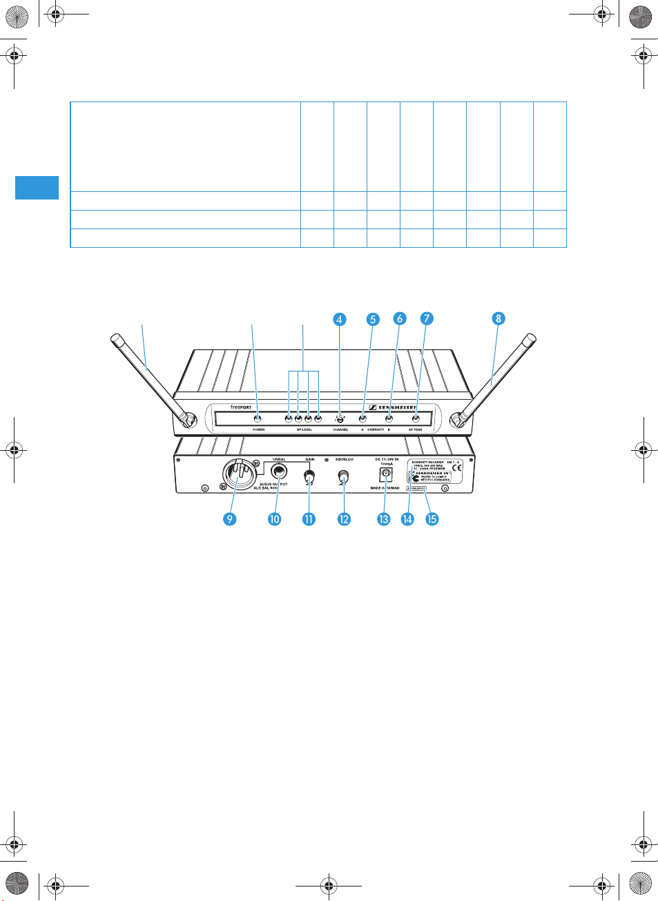
Empfänger EM 1
Bedienelemente
Antenne A
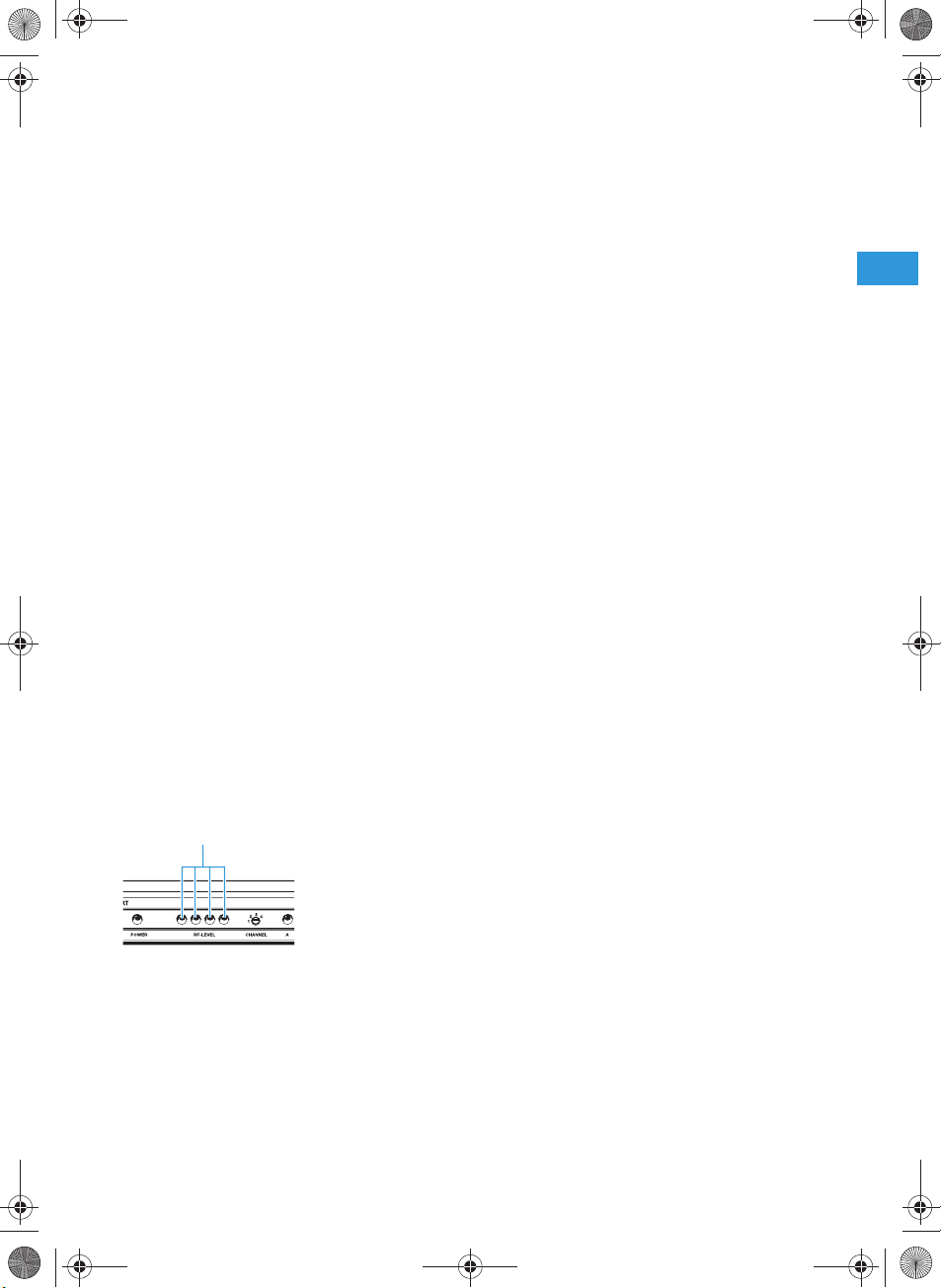
Betriebsanzeige, grüne LED (POWER)
쐋 Anzeige des empfangenen Funksignal-
Pegels, vier grüne LEDs (RF LEVEL)
Kanalwahlschalter CHANNEL (1 bis 4)
Diversity-Anzeige, gelbe LED A
(leuchtet, wenn Antenne aktiv ist)
Diversity-Anzeige, gelbe LED B
(leuchtet, wenn Antenne aktiv ist)
AF PEAK, rote LED (leuchtet, wenn der
Audiopegel zu hoch ist)
4
Antenne B
XLR-3-Buchse (male) für Audio-Ausgang,
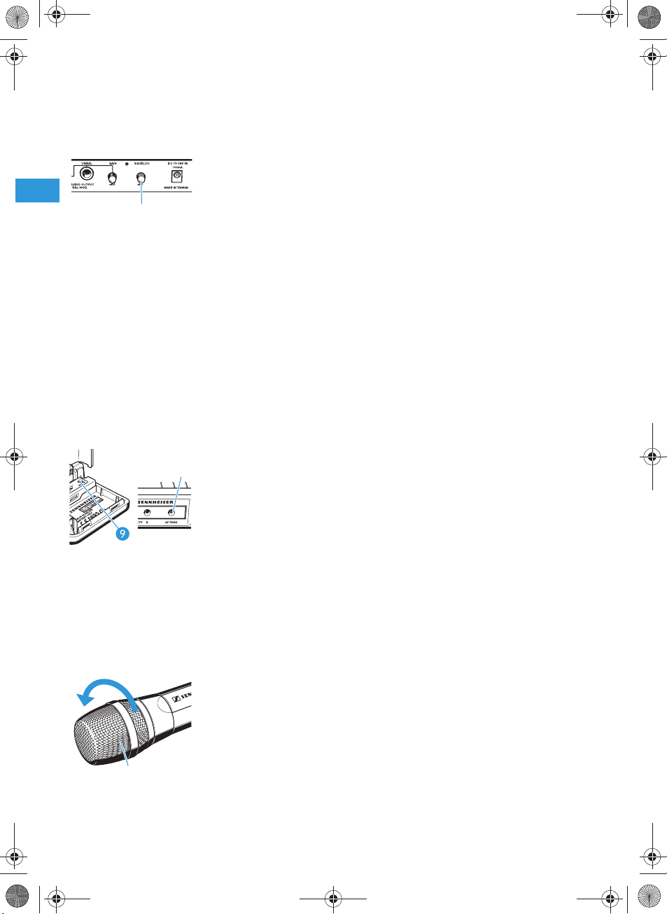
symmetrisch (AUDIO OUTPUT XLR BAL)
6,3-mm-Klinkenbuchse für Audio-Aus-
gang, unsymmetrisch
(AUDIO OUTPUT UNBAL)
Einsteller Audio-Ausgangspegel (GAIN)
Einsteller Rauschsperren-Schwelle
(SQUELCH)
Hohlklinkenbuchse für Anschluss des
Netzteils (DC 11–18 V IN, 100 mA)
Typenschild
Seriennummer
Page 9

freeport_514013_0808_Sp5.book Seite 5 Freitag, 29. August 2008 12:08 12
Empfänger anschließen
왘 Stecken Sie den Hohlklinkenstecker des Netzteils in die Buchse
und schließen sie das Netzteil an das Stromnetz an. Die grüne
Betriebsanzeige (POWER) leuchtet und der Empfänger ist
betriebsbereit.
왘 Zum Deaktivieren ziehen Sie den Netzstecker aus der Steckdose.
Antennen ausrichten
왘 Stellen Sie die Antennen auf und richten Sie sie V-förmig aus.
Die LEDs A und B zeigen an, welcher Empfänger-Zweig (und damit
welche Antenne) aktiv ist.
Verstärker/Mischpult an Empfänger anschließen
왘 Schließen Sie den Verstärker/das Mischpult an die XLR-Buchse
oder die 6,3-mm-Klinkenbuchse an.
왘 Passen Sie mit dem Einsteller GAIN den Pegel des Audio-Aus-
gangs an die Empfindlichkeit des nachfolgenden Verstärkers bzw.
des Mischpults an. Der Einsteller GAIN wirkt gleichzeitig auf die
XLR-3-Buchse und die 6,3-mm-Klinkenbuchse. Ist der Pegel zu hoch
eingestellt, hat das Verzerrungen des Tonsignals zur Folge. Ist der
Pegel zu niedrig eingestellt, ist das Tonsignal verrauscht.
Kanal auswählen und wechseln
Sie können am Empfänger den Kanal im laufenden Betrieb wechseln. Er
empfängt dann sofort auf dem neuen Kanal.
왘 Stellen Sie mit einem kleinen Schraubendreher den Kanalwahlschal-
ter auf den gewünschten Kanal ein. Sie können zwischen vier verschiedenen Kanälen umschalten (siehe „Kanal auswählen“ auf
Seite 10).
5
Page 10
freeport_514013_0808_Sp5.book Seite 6 Freitag, 29. August 2008 12:08 12
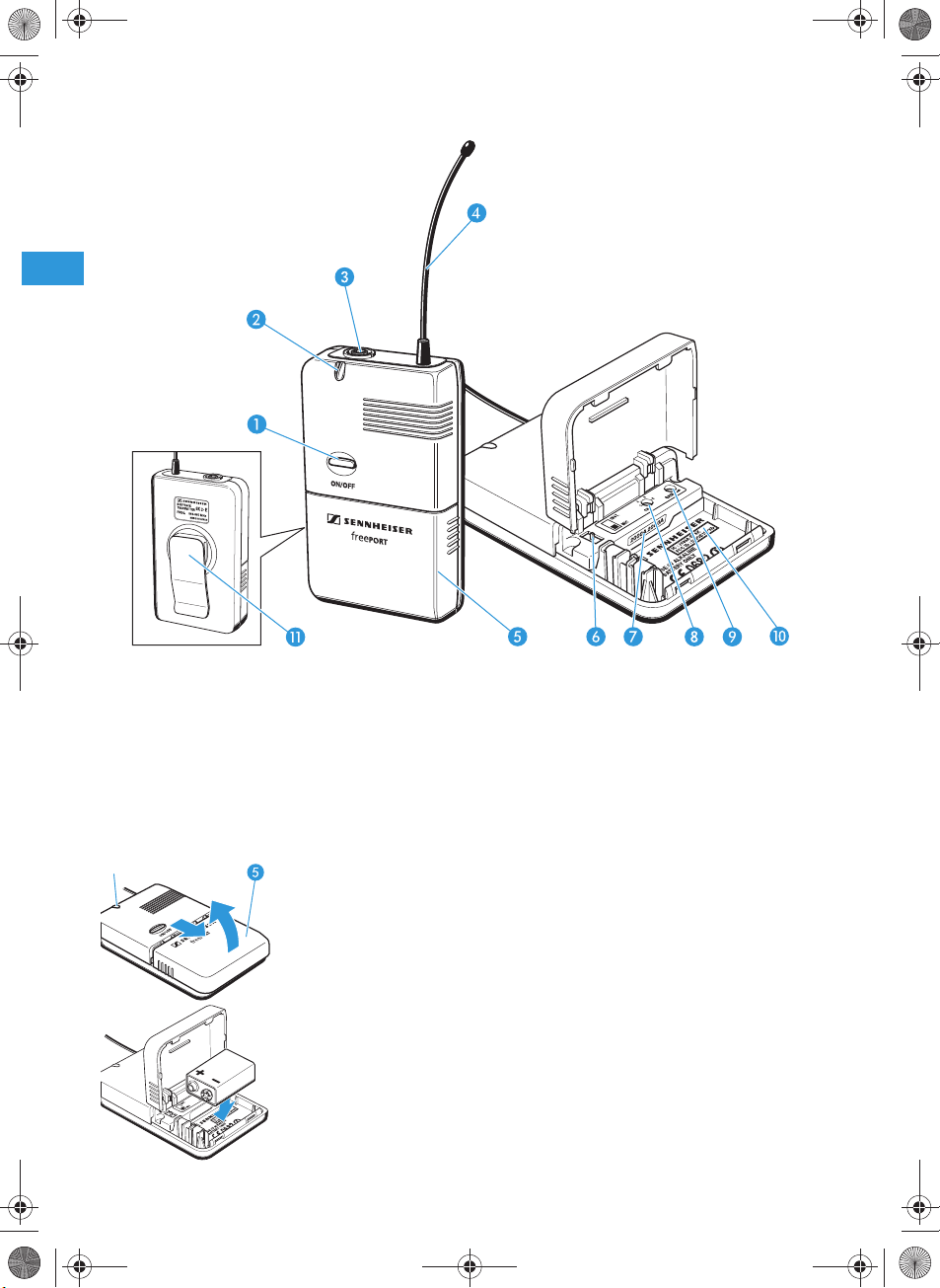
Taschensender SK 2
Bedienelemente
Schalter ON/OFF
Betriebs- und Batterieanzeige, rote LED
쐋 Mikrofon- und Instrumenteneingang,
3,5-mm-Klinkenbuchse (verriegelbar)
Antenne (abschraubbar)
Abdeckung des Batteriefachs
Batterien einsetzen/wechseln
Wir empfehlen, den Taschensender mit einer 9-Volt-Alkali-ManganBatterie zu betreiben. Beim Betrieb mit 9-Volt-Akkus ist die Betriebszeit
wesentlich geringer.
왘 Öffnen Sie das Batteriefach, indem Sie die Batteriefachabdeckung
zunächst in Pfeilrichtung herunterziehen und dann aufklappen.
왘 Setzen Sie die Batterie wie nebenstehend gezeigt ein. Achten Sie
dabei auf die Polarität.
왘 Schließen Sie das Batteriefach.
Hinweis:
Wechseln Sie die Batterie schnellstmöglich, wenn während des
Betriebs die rote LED erlischt.
6
Umschalter MIC/INST
Seriennummer
Kanalwahlschalter CH (1 bis 4)
Einsteller Aussteuerung GAIN
Typenschild
Gürtelclip
Page 11
freeport_514013_0808_Sp5.book Seite 7 Freitag, 29. August 2008 12:08 12
Mikrofon oder Instrumentenkabel anschließen
Der Audio-Eingang ist sowohl für den Anschluss des Ansteckmikrofons
ME 2 als auch für den Anschluss von Instrumenten (z. B. Gitarren) ausgelegt.
왘 Schließen Sie den 3,5-mm-Klinkenstecker des Mikrofon- oder
Instrumentenkabels in die 3,5-mm-Klinkenbuchse 쐋 an.
왘 Prüfen Sie die Einstellung des Schiebeschalters MIC/INST , mit
dem Sie zwischen Mikrofon- und Instrumenten-Betrieb umschalten,
und passen Sie die Einstellung ggf. an.
왘 Stellen Sie mit dem Einsteller GAIN die Aussteuerung so ein, dass
Sie am Empfänger ein gutes Tonsignal erhalten (keine Verzerrungen
und kein Rauschen).
Mikrofon befestigen und ausrichten
Befestigen Sie das Mikrofon ME 2 mit der Ansteckklammer an der Kleidung, z. B. am Jackenrevers. Verlegen Sie das Kabel so, dass keine
Geräusche durch Reibung an der Kleidung entstehen und sich Mikrofonleitung und Antenne nicht kreuzen. Das Mikrofon hat eine kugelförmige
Charakteristik. Sie brauchen es daher nicht genau auszurichten, sollten
es aber möglichst dicht an der Tonquelle befestigen.
Taschensender an der Kleidung befestigen
왘 Befestigen Sie den Taschensender mit dem Gürtelclip an der Klei-
dung. Achten Sie darauf, dass die Antenne nicht am Körper anliegt
und nicht abgeknickt wird.
Taschensender ein-/ausschalten
왘 Drücken Sie den Schalter ON/OFF , um den Taschensender ein-
oder auszuschalten. Ist der Taschensender eingeschaltet, leuchtet
die rote LED .
Hinweis:
Nehmen Sie die Batterie aus dem Sender, wenn Sie das Gerät längere Zeit nicht benutzen.
Kanal auswählen und wechseln
왘 Schalten Sie den Sender aus, bevor Sie den Kanal wechseln.
왘 Stellen Sie mit einem kleinen Schraubendreher den Kanalwahlschal-
ter auf den gewünschten Kanal ein. Sie können zwischen vier verschiedenen Kanälen umschalten. Wenn Sie den Taschensender
wieder einschalten, sendet er auf dem neuen Kanal (siehe „Kanal
auswählen“ auf Seite 10).
7
Page 12
freeport_514013_0808_Sp5.book Seite 8 Freitag, 29. August 2008 12:08 12
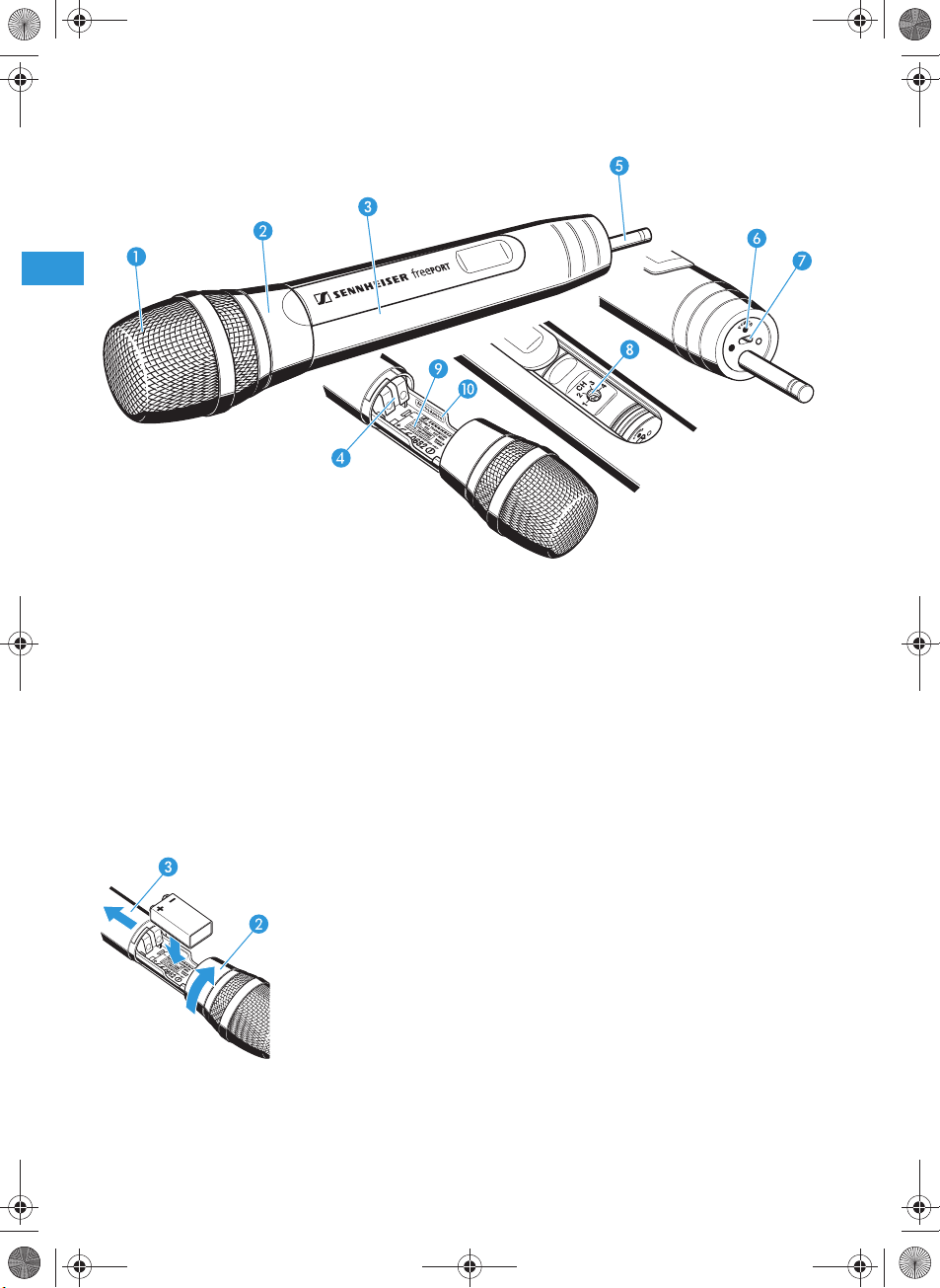
Funkmikrofon SKM 3
Bedienelemente
Einsprachekorb
Verriegelungsring Batteriefach
쐋 Griff des Funkmikrofons
Batteriefach (von außen nicht sichtbar)
Antenne (abschraubbar)
Betriebs- und Batterieanzeige,
rote LED (POWER)
Schalter ON/OFF
Kanalwahlschalter CH (1 bis 4)
Typenschild
Seriennummer
Hinweis:
Die Mikrofonkapsel des Funkmikrofons kann nicht gewechselt werden.
Batterien einsetzen/wechseln
Wir empfehlen, das Funkmikrofon mit einer 9-Volt-Alkali-Mangan-Batterie zu betreiben. Beim Betrieb mit 9-Volt-Akkus ist die Betriebszeit
wesentlich geringer.
왘 Drehen Sie den Verriegelungsring des Batteriefachs in Pfeilrich-
tung.
왘 Ziehen Sie den Griff des Funkmikrofons 쐋 in Pfeilrichtung bis zum
Anschlag herunter.
왘 Setzen Sie die Batterie wie nebenstehend gezeigt ein. Achten Sie
dabei auf die Polarität.
왘 Schließen und verriegeln Sie das Funkmikrofon wieder.
Hinweis:
Wechseln Sie die Batterie schnellstmöglich, wenn während des
Betriebs die rote LED erlischt.
8
Page 13
freeport_514013_0808_Sp5.book Seite 9 Freitag, 29. August 2008 12:08 12
Funkmikrofon ein-/ausschalten
왘 Mit dem Schalter ON/OFF schalten Sie das Funkmikrofon ein bzw.
aus. Ist das Funkmikrofon eingeschaltet, leuchtet die rote LED .
Hinweis:
Nehmen Sie die Batterie aus dem Sender, wenn Sie das Gerät längere Zeit nicht benutzen.
Kanal auswählen und wechseln
왘 Schalten Sie das Funkmikrofon aus.
왘 Öffnen Sie das Funkmikrofon (siehe „Batterien einsetzen/wech-
seln“ auf Seite 8).
왘 Stellen Sie mit einem kleinen Schraubendreher den Kanalwahlschal-
ter auf den gewünschten Kanal ein. Sie können zwischen vier verschiedenen Kanälen umschalten (siehe „Kanal auswählen“ auf
Seite 10).
왘 Schließen und verriegeln Sie das Funkmikrofon wieder.
왘 Schalten Sie das Funkmikrofon wieder ein.
Austeuerung des Funkmikrofons
Durch den Abstand zum Mund können Sie die Lautstärke und die Tiefenwiedergabe variieren.
Das System optimieren
Führen Sie vor Beginn der Übertragung einen „Soundcheck“ durch und
optimieren Sie das System wie folgt:
Empfang optimieren
Am Empfänger zeigen die vier LEDs (RF LEVEL) 쐋 die Stärke des empfangenen Funksignals an. Schreiten Sie mit dem Sender den Übertragungsbereich ab und prüfen Sie, ob das empfangene Funksignal überall
ausreicht. Die Übertragung ist gut, wenn alle vier LEDs leuchten. Beachten Sie dabei:
y Die Reichweite des Systems ist abhängig von den örtlichen Bedingun-
gen und kann bis zu 100 m betragen. Halten Sie zwischen Sender und
Empfänger einen Mindestabstand von 3 m ein. Sorgen Sie für freie
Sicht zwischen Sende- und Empfangsantenne.
y Betreiben Sie das System nicht in der Nähe von Stahl und Beton. Com-
puter oder Mobil-Telefone in unmittelbarer Nähe der Antenne stören
die Übertragung.
y Jeder Sender benötigt einen Empfänger. Verwenden Sie für den
gleichzeitigen Betrieb mehrerer Übertragungsstrecken unterschiedliche Kanäle.
9
Page 14
freeport_514013_0808_Sp5.book Seite 10 Freitag, 29. August 2008 12:08 12
Rauschsperren-Schwelle einstellen
Störungen durch andere Sendestrecken beseitigen Sie wie folgt:
왘 Schalten Sie den Sender aus. Der Empfänger sollte nun kein Signal
empfangen.
왘 Empfängt der Empfänger trotzdem ein Signal, müssen Sie die Ein-
stellung des Reglers SQUELCH so lange erhöhen, bis Sie kein Signal mehr empfangen. Lässt sich das Signal so nicht beseitigen,
müssen Sie an Sender und Empfänger einen anderen Kanal einstellen.
왘 Schalten Sie nun den Sender ein und prüfen Sie, ob der Empfänger
den Sender empfängt.
Hinweis:
Ein hoher Wert der Rauschsperren-Schwelle vermindert die Reichweite der Übertragungsstrecke. Stellen Sie die RauschsperrenSchwelle deshalb stets auf den minimal nötigen Wert ein.
Kanal auswählen
Sender und Empfänger haben je vier Kanäle mit aufeinander abgestimmten Frequenzen.
왘 Stellen Sie Sender und Empfänger stets auf denselben Kanal ein.
10
Aussteuerung des Senders einstellen
왘 Stellen Sie am Taschensender SK 2 mit dem Einsteller Aussteuerung
GAIN die Aussteuerung so ein, dass auch bei lauten Passagen die
Übersteuerungsanzeige (AF PEAK) am Empfänger EM 1 nicht
aufleuchtet.
Pflege und Wartung
Reinigen Sie die Geräte von Zeit zu Zeit mit einem leicht feuchten Tuch.
Hinweis:
Verwenden Sie auf keinen Fall Löse- oder Reinigungsmittel.
Reinigen Sie den Einsprachekorb des Funkmikrofons SKM 3:
왘 Schrauben Sie den Einsprachekorb vom Funkmikrofon ab (gegen
den Uhrzeigersinn drehen).
왘 Entfernen Sie den Schaumstoff-Einsatz und reinigen Sie den Ein-
sprachekorb mit einem leicht feuchten Tuch.
왘 Setzen Sie den trockenen Schaumstoff-Einsatz wieder ein und
schrauben Sie den Einsprachekorb auf.
Page 15
freeport_514013_0808_Sp5.book Seite 11 Freitag, 29. August 2008 12:08 12
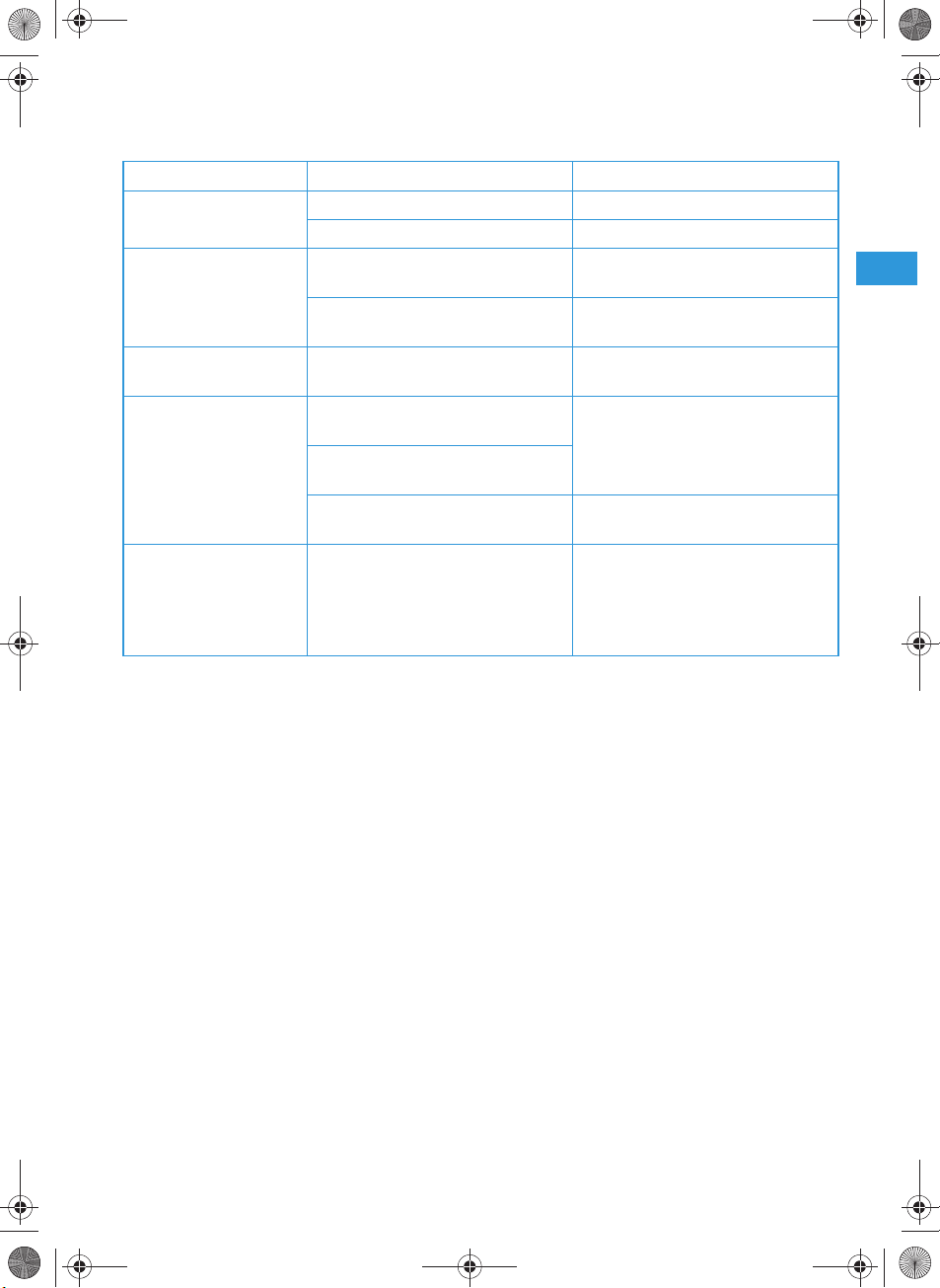
Wenn Störungen auftreten
Problem Mögliche Ursache Mögliche Abhilfe
keine Betriebsanzeige Verbrauchte Batterie Batterie austauschen
Kein Netzanschluss (Empfänger) Netzanschluss prüfen
kein Funksignal Sender und Empfänger arbeiten
nicht auf demselben Kanal
Reichweite der Funkstrecke ist
überschritten
Funksignal vorhanden,
kein Tonsignal
Tonsignal verrauscht
bzw. verzerrt
Störgeräusche Bei fast entladener Batterie
Rauschsperren-Schwelle am Empfänger ist zu hoch eingestellt
Aussteuerung des Senders ist zu
niedrig bzw. zu hoch
am Sender SK 2 ist der Schiebeschalter MIC/INST falsch eingestellt
Ausgangspegel des Empfängers ist
zu niedrig bzw. zu hoch
erzeugen die Sender möglicherweise Störgeräusche, die zu
Schädigungen des
PA-Systems führen können.
am Sender und Empfänger
denselben Kanal einstellen
Abstand zwischen Empfänger
und Sender verringern
siehe „Rauschsperren-Schwelle
einstellen“ auf Seite 10
siehe „Mikrofon oder Instrumentenkabel anschließen“ auf Seite 7
siehe „Verstärker/Mischpult an
Empfänger anschließen“ auf Seite 5
Bitte wechseln Sie nach dem
Erlöschen der LED schnellstmöglich die Batterie oder schalten
Sie den Sender aus.
Zubehör und Varianten
04839 MZW 1 Wind- und Poppschutz für SKM 3
76670 MZQ 1 Mikrofonklemme für SKM 3
05018 ME 2 Ansteckmikrofon für SK 2, dauerpolarisiertes Kondensatormikrofon,
Kugelcharakteristik
05019 ME 3 Headsetmikrofon für SK 2, dauerpolarisiertes Kondensatormikrofon,
Supernierencharakteristik
05020 ME 4 Ansteckmikrofon für SK 2, dauerpolarisiertes Kondensatormikrofon,
Nierencharakteristik
512889 CI1-fp Gitarrenkabel
11
Page 16
freeport_514013_0808_Sp5.book Seite 12 Freitag, 29. August 2008 12:08 12
Technische Daten der Sets
System-Eigenschaften
Sende-/Empfangsfrequenzen 4 Sende-/Empfangsfrequenzen im UHF-Bereich
Bereich A: 719 bis 721 MHz
(719,15 – 719,75 – 720,15 – 720,85 MHz)
Bereich B: 691 bis 693 MHz
(691,00 – 691,40 – 692,35 – 692,90 MHz)
Bereich C : 742,5 bis 744,5 MHz
(742,65 – 743,35 – 743,85 – 744,45 MHz)
Bereich E: 863 bis 865 MHz (863,1 – 863,7 – 864,1 – 864,9 MHz)
Schaltbandbreite 2 MHz
Signal-Rausch-Abstand
Klirrfaktor (1kHz)
Temperaturbereich –10 bis +45 °C / 95 %
Einzelgeräte
Spannungsversorgung 12V DC
Betriebszeit
(mit Alkali-Mangan-Batterien)
Frequenzgang – 60...16.000 Hz
HF-Ausgangsleistung (–3 dB) – 10 mW 10 mW
NF-Ausgangsspannung
6,3-mm-Klinkenbuchse (unsym.):
XLR-Buchse (sym.):
Abmessungen ca. 35 x 213 x 98 mm ca. 60 x 100 x 30 mm
Gewicht ca. 570 g ca. 90 g ca. 210 g
Mikrofontyp – – dynamisch
Richtcharakteristik – – Niere
>
95 dB(A)
<
1 %
RH
Empfänger EM 1 Taschensender SK 2 Funkmikrofon SKM 3
/100 mA 9V PP3 9V PP3
NOM
– ca. 10 h ca. 10 h
±
3 dB 80...16.000 Hz ± 3 dB
––
max. +10 dB
max. +16 dB
u
u
ca. 285 mm;
(mit Gürtelclip)
∅
ca. 35 x 50 mm
Ansteckmikrofon ME 2
Mikrofontyp
Richtcharakteristik
12
dauerpolarisiertes Kondensatormikrofon
Kugel
Page 17
freeport_514013_0808_Sp5.book Seite 13 Freitag, 29. August 2008 12:08 12
Zulassungen
In Übereinstimmung mit EMV EN 301489-1/-9
Funk EN 301357-1/-2
Sicherheit EN 60065
Zugelassen auch für
Industry Canada RSS 210, IC: 2099A
SKM3/EM1-A/-C IC: 2099A-FPSKMEM
SKM3/EM1-B IC: 2099A-FPSKMEMB
SK2-A/-C IC: 2099A-FPSK
SK2-B IC: 2099A-FPSKB
FCC-Part 74 SK2-A/-C FCC ID: DMOB1FPXD
SK2-B FCC ID: DMOB2FPSK
SKM3-A/-C FCC ID: DMOH1FPXD
SKM3-B FCC ID: DMOH2FPSKM
Der Sender mit dem Frequenzbereich E (863–865 MHz) kann in folgenden Ländern zulassungsfrei
betrieben werden:
AT, BA, BE, CH, CY, CZ, DE, DK, EE, ES, FI, FR, GB, GR, HU, IE, IS, IT, LI, LT, LU, ME, MK, MT, NL, NO, PL, PT, RO,
RS, RU, SE, SI, SK, TR, UA.
Für die Sender der Frequenzbereiche A (719–721 MHz), B (691–693 MHz) und C (742,5–744,5 MHz)
zu
müssen Sie eine Funk
lassung beantragen. Der Bereich B ist nur zum Betrieb in USA und Kanada vor-
gesehen.
Frequenzbereich Presentation Set Instrument Set Vocal Set
691–693 MHz:
mit US-Netzteil freePort fp 12-B-US freePort fp 72-B-US freePort fp 35-B-US
719–721 MHz:
mit US-Netzteil freePort fp 12-A-US freePort fp 72-A-US freePort fp 35-A-US
742,5–744,5 MHz:
mit EU-Netzteil freePort fp 12-C-EU freePort fp 72-C-EU freePort fp 35-C-EU
mit US-Netzteil freePort fp 12-C-US freePort fp 72-C-US freePort fp 35-C-US
863–865 MHz:
mit EU-Netzteil freePort fp 12-E-EU freePort fp 72-E-EU freePort fp 35-E-EU
mit UK-Netzteil freePort fp 12-E-UK freePort fp 72-E-UK freePort fp 35-E-UK
Steckerbelegung
EM 1:
6,3-mm-Stere
Klinkenstecker,
unsym.
NC/GND
EM 1:
6,3-mm-Mon
o-
Klinkenstecker,
unsym.
o-
EM 1:
XLR-3-Stecker
(female), sym.
21
+
3
EM 1:
Hohlklinkenstecker
zur Stromversorgung
SK 2:
3,5-mm-Klinkenstecker
NC/GND
Instr./MIC
13
Page 18
0682
freeport_514013_0808_Sp5.book Seite 14 Freitag, 29. August 2008 12:08 12
Herstellererklärungen
Garantie
Sennheiser GmbH & Co. KG übernimmt für dieses Produkt eine Garantie von 24 Monaten.
Die aktuell geltenden Garantieleistungen können Sie über das Internet www.sennheiser.com oder Ihren Sennhei-
ser-Partner beziehen.
EG-Konformitätserklärung
Diese Geräte ensprechen den grundlegenden Anforderungen und den weiteren Vorgaben der Richtlinien 1999/5/
EU, 2004/108/EU und 2006/95/EU. Die Erklärung steht im Internet unter www.sennheiser.com zur Verfügung.
Vor Inbetriebnahme sind die jeweiligen länderspezifischen Vorschriften zu beachten!
Akkus und Batterien
Die mitgelieferten Akkus oder Batterien sind recyclingfähig.
Bitte entsorgen Sie die Akkus über den Batteriecontainer oder den Fachhandel. Entsorgen Sie nur leere
Batterien oder Akkkus, um den Umweltschutz zu gewährleisten.
WEEE-Erklärung
Ihr Sennheiser-Produkt wurde mit hochwertigen Materialien und Komponenten entworfen und hergestellt, die recycelbar sind und wieder verwendet werden können. Dieses Symbol bedeutet, dass elektrische und elektronische Geräte am Ende ihrer Nutzungsdauer vom Hausmüll getrennt entsorgt werden
müssen.
Bitte helfen Sie mit, die Umwelt, in der wir leben, zu erhalten.
Bitte entsorgen Sie dieses Gerät bei Ihrer örtlichen kommunalen Sammelstelle oder im Recycling Center.
14
Page 19
freeport_514013_0808_Sp5.book Seite 1 Freitag, 29. August 2008 12:08 12
Contents
Important safety instructions ......................................................... 2
The freePORT systems ...................................................................... 3
Delivery includes .......................................................................... 4
EM 1 receiver ......................................................................................4
SK 2 bodypack transmitter .............................................................. 6
SKM 3 radio microphone .................................................................. 8
Setting up the system ...................................................................... 9
Care and maintenance ....................................................................10
If problems occur... ..................................................................... 11
Accessories and variants ................................................................11
Specifications of the freePORT systems ......................................12
Connector assignment ..............................................................13
Manufacturer declarations .............................................................14
Warranty .....................................................................................14
CE Declaration of Conformity ..................................................14
Batteries or rechargeable batteries .......................................14
WEEE Declaration .......................................................................14
Statements regarding the FCC and Industry Canada rules 14
Thank you for choosing Sennheiser!
We have designed this product to give you reliable operation over many
years. Over half a century of accumulated expertise in the design and
manufacture of high-quality electro-acoustic equipment have made
Sennheiser a world-leading company in this field.
Please take a few moments to read these instructions carefully, as we
want you to enjoy your new Sennheiser products quickly and to the
fullest.
1
Page 20
freeport_514013_0808_Sp5.book Seite 2 Freitag, 29. August 2008 12:08 12
Important safety instructions
y Read this instruction manual.
y Keep this instruction manual in a safe place. Always include this
instruction manual when passing the device and the mains unit on to
third parties.
y Heed all warnings and follow all instructions.
y Clean the device and the mains unit only with a dry cloth.
y Refer all servicing to qualified service personnel. Servicing is required
if the device or the mains unit has been damaged in any way, liquid
has been spilled, objects have fallen inside, the device or the mains
unit has been exposed to rain or moisture, does not operate properly
or has been dropped.
y WARNING: To reduce the risk of fire or electric shock, do not expose
the device and the mains unit to rain or moisture. Do not place objects
filled with liquids, such as vases or coffee cups, on the device.
y Only use the supplied mains unit.
y Disconnect the mains connector from the wall socket
– to completely disconnect the device from the mains,
– during lightning storms or when unused for long periods of time.
y The mains unit must be operated only from the type of power source
specified in the chapter “Specifications of the freePORT systems”
(page 12).
y Ensure that the mains unit is
– always readily operable and easily accessible,
– properly plugged into the wall socket,
– only operated within the permissible temperature range,
– not covered or exposed to direct sunlight for longer periods of time
in order to prevent heat accumulation (see “Specifications of the
freePORT systems” on page 12).
y Do not block any ventilation openings. Install the device and the
mains unit in accordance with the manufacturer’s instructions.
y Do not install the device and the mains unit near any heat sources.
y Only use attachments/accessories specified by Sennheiser.
2
Page 21

freeport_514013_0808_Sp5.book Seite 3 Freitag, 29. August 2008 12:08 12
The freePORT systems
Designed for different areas of application, the freePORT systems are
available in three variants.
y Presentation Set:
This system is ideal for presentation applications. The unobtrusive
ME 2 clip-on microphone is virtually invisible.
y Instrument Set:
This system is for connecting musical instruments (e.g. guitar) which
have a ¼” ( 6.3 mm) j ack sock et directly to the bodypack transmitter.
y Vocal Set:
This system is ideal for vocal and speech applications.
Transmitters and receivers of the freePORT systems have four factorypreset frequencies for direct channel selection – ready for immediate
use after switch-on.
The freePORT systems are available in three UHF frequency ranges:
y Frequency range A: 719 to 721 MHz
y Frequency range B: 691 to 693 MHz
y Frequency range C: 742.5 to 744.5 MHz
y Frequency range E: 863 to 865 MHz
Notes:
Use of A, B and C frequency ranges must be licensed. Most EU
countries do not require licensing for use of frequency range E.
Frequency range B (691 to 693 MHz) is intended for use solely in
the USA and Canada.
Please be legal and observe the country-specific regulations of the
licensing authorities. Sennheiser are not responsible if you operate
illegally.
To avoid interfering with other users, the transmitter should be
switched off when not in use.
Features of the freePORT systems:
y Up to four transmission links per frequency range which can be
operated simultaneously
y Reliable transmission technology
y Diversity technology for minimizing dropouts in the reception
y Adjustable squelch for eliminating RF interference
y Rugged housings
y Crystal-clear reception due to dynamic processor
3
Page 22

freeport_514013_0808_Sp5.book Seite 4 Freitag, 29. August 2008 12:08 12
Delivery includes
FreePORT systems
Stand mount
EM 1 receiver
SK 2
bodypack transmitter
SKM 3
radio microphone
Mains unit (NTxy)
ME 2
clip-on microphone
¼” (6.3 mm) jack cable
Instructions for use
Presentation Set XX XX X
Instrument Set XXXXX
Vocal Set XXX XX
EM 1 receiver
Operating controls
Antenna A
Operation indication, green LED (POWER)
쐋 RF level indication, four green LEDs
(RF LEVEL)
Channel selector switch CHANNEL (1 to 4)
Diversity indication, yellow LED A
(lights up if antenna is active)
Diversity indication, yellow LED B
(lights up if antenna is active)
AF PEAK, red LED (lights up if the audio
level is too high)
4
Antenna B
Audio output, XLR-3M socket, balanced
(AUDIO OUTPUT XLR BAL)
Audio output, ¼” (6.3 mm) jack socket,
unbalanced (AUDIO OUTPUT UNBAL)
Audio output level control (GAIN)
Squelch threshold control (SQUELCH)
DC socket for connection of mains unit
(DC 11–18 V IN, 100 mA)
Type plate
Serial number
Page 23

freeport_514013_0808_Sp5.book Seite 5 Freitag, 29. August 2008 12:08 12
Connecting the receiver
왘 Insert the DC connector on the mains cable into the DC socket and
connect it to the mains. The green LED for operation indication
(POWER) lights up and the receiver is ready for operation.
왘 To deactivate the receiver, remove the mains plug from the mains
outlet.
Aligning the antennas
왘 Set up the antennas and align them upwards in a V-shape.
The LEDs A and B indicate which diversity section (i.e. which
antenna) is active.
Connecting the amplifier/mixing console
왘 Connect the amplifier/mixing console to the XLR-3M socket or
the ¼” (6.3 mm) jack socket .
왘 Use the GAIN control to adapt the level of the audio output to the
input of the amplifier or mixing console. The adjusted audio output
level is common for both sockets. If the level is adjusted too high,
the audio signal will be distorted. If, on the other hand, the level is
adjusted too low, this will result in an audio signal with high
background noise.
Selecting and changing a channel
You can change the channel on the receiver during running operation.
The receiver then immediately receives on the new channel.
왘 Use a small screwdriver to set the channel selector switch to the
desired channel. You can switch between four different channels
(“Selecting a channel”).
5
Page 24

freeport_514013_0808_Sp5.book Seite 6 Freitag, 29. August 2008 12:08 12
SK 2 bodypack transmitter
Operating controls
ON/OFF button
Operation and battery status indication, red LED
쐋 Microphone/instrument input,
3.5 mm jack socket (lockable)
Antenna (can be screwed off)
Battery compartment cover
Inserting/replacing the battery
We recommend powering the bodypack transmitter by a 9 V PP3
alkaline battery (IEC 6 LR 61). If powered by a rechargeable 9 V battery,
the operating time will be drastically reduced.
왘 Open the battery compartment by first sliding the battery
compartment cover in the direction of the arrow. Then flip the
battery compartment cover open.
왘 Insert the battery as shown. Please observe correct polarity when
inserting the battery.
왘 Close the battery compartment.
Note:
When the red LED goes off during operation, you must replace
the battery as soon as possible.
6
MIC/INST slide switch
Serial number
Channel selector switch CH (1 to 4)
Sensitivity control GAIN
Type plate
Belt clip
Page 25

freeport_514013_0808_Sp5.book Seite 7 Freitag, 29. August 2008 12:08 12
Connecting the microphone/instrument cable
The audio input is designed for the connection of both the ME 2 clip-on
microphone and instruments (e.g. guitars).
왘 Connect the 3.5 mm jack plug from the microphone/instrument
cable to the 3.5 mm jack socket 쐋.
왘 Check the setting of the MIC/INST slide switch which allows you
to switch between microphone and instrument operation. If
necessary, readjust the setting.
왘 Use the GAIN control to adjust the transmitter sensitivity so that
the receiver receives a good audio signal (no distortion and no
background noise).
Attaching and positioning the microphone
Use the microphone clip to attach the ME 2 clip-on microphone to
clothing (e.g. tie, lapel). Conduct the microphone cable so that noise due
to friction is avoided and make sure that the antenna and the cable do
not cross. The omni-directional microphone picks up sound equally from
all directions. However, it should be attached as close as possible to the
sound source.
Attaching the bodypack transmitter to clothing
왘 Use the supplied belt clip to attach the bodypack transmitter to
clothing. Make sure that the antenna is at least 1 cm away from the
body and is not kinked.
Switching the bodypack transmitter on/off
왘 Press the ON/OFF button to switch the bodypack transmitter on
or off. If the bodypack transmitter is switched on, the red LED
lights up.
Note:
Remove the battery when the transmitter will not be used for
extended periods of time.
Selecting and changing a channel
왘 Switch off the transmitter before you change the channel.
왘 Use a small screwdriver to set the channel selector switch to the
desired channel. You can switch between four different channels.
When you switch on the bodypack transmitter again, it will transmit
on the new channel (“Selecting a channel”).
7
Page 26

freeport_514013_0808_Sp5.book Seite 8 Freitag, 29. August 2008 12:08 12
SKM 3 radio microphone
Operating control
Sound inlet basket
Locking ring of battery compartment
쐋 Body of radio microphone
Battery compartment (not visible from
outside)
Antenna (can be screwed off)
Operation and battery status indication,
red LED (POWER)
ON/OFF switch
Channel selector switch CH (1 to 4)
Type plate
Serial number
Note:
The microphone head of the radio microphone cannot be changed.
Inserting/replacing the battery
We recommend powering the radio microphone by a 9 V PP3 alkaline
battery (IEC 6 LR 61). If powered by a rechargeable 9 V battery, the
operating time will be drastically reduced.
왘 Turn the locking ring of the battery compartment in the direction
of the arrow.
왘 Pull the body of the radio microphone 쐋 in the direction of the
arrow as far as it will go.
왘 Insert the battery as shown. Please observe correct polarity when
inserting the battery.
왘 Close and lock the radio microphone.
Note:
When the red LED goes off during operation, you must replace
the battery as soon as possible.
8
Page 27

freeport_514013_0808_Sp5.book Seite 9 Freitag, 29. August 2008 12:08 12
Switching the radio microphone on/off
왘 Use the ON/OFF switch to switch the radio microphone on or off.
If the radio microphone is switched on, the red LED lights up.
Note:
Remove the battery when the transmitter will not be used for
extended periods of time.
Selecting and changing a channel
왘 Switch off the radio microphone.
왘 Open the radio microphone (“Inserting/replacing the battery”).
왘 Use a small screwdriver to set the channel selector switch to the
desired channel. You can switch between four different channels
(“Selecting a channel”).
왘 Close and lock the radio microphone.
왘 Switch on the radio microphone again.
Sensitivity of the radio microphone
You can vary the bass reproduction by increasing/decreasing the
talking distance.
Setting up the system
Before starting transmission, do a soundcheck and set up the system as
follows:
Setting up the reception
The receiver’s four LEDs (RF LEVEL) 쐋 indicate the level of the received
RF signal. With the transmitter, walk up and down the transmission
area and check if the received RF signal is sufficient everywhere.
Reception is good if all four LEDs light up. Please observe the following:
y Transmission range depends to a large extent on location and can be
up to 100 m. Observe a minimum distance of 3 m between
transmitter and receiver. There should be a “free line of sight”
between transmitting and receiving antennas.
y Do not operate the system close to metal objects such as cross
members or reinforced-concrete walls. Computers or mobile phones
in direct proximity to the antenna will interfere with the reception.
y Each transmitter requires a receiver. When using several trans-
mission links simultaneously, make sure that all transmission links
operate on different channels.
9
Page 28

freeport_514013_0808_Sp5.book Seite 10 Freitag, 29. August 2008 12:08 12
Adjusting the squelch threshold
Interference due to other transmission links can be eliminated as
follows:
왘 Switch off the transmitter. The receiver should no longer receive a
signal.
왘 If the receiver still receives a signal, use the SQUELCH control to
increase the squelch threshold so that the signal will no longer be
received. If the signal cannot be eliminated in this way, set the
transmitter and the receiver to a different channel.
왘 Switch on the transmitter again and check if the receiver receives
the transmitter signal.
Note:
If the squelch threshold is adjusted too high, the transmission range
will be reduced. Therefore, always adjust the squelch treshold to the
lowest possible setting.
Selecting a channel
Transmitters and receivers have four channels respectively with
intermodulation-free frequencies.
Note:
These frequencies are different to those in evolution systems and
freePORT systems should not be used together with evolution systems without great care.
10
왘 Always set the transmitter and the receiver to the same channel.
Adjusting the transmitter sensitivity
왘 Use the GAIN control on the SK 2 bodypack transmitter to adjust
the sensitivity so that even during the loudest passages the
AF PEAK LED on the EM 1 receiver does not light up.
Care and maintenance
Use a slightly damp cloth to clean the units from time to time.
Note:
Do not use any cleansing agents or solvents.
To clean the SKM 3’s sound inlet basket:
왘 Unscrew the sound inlet basket (turn counterclockwise) and
remove it.
왘 Remove the foam insert and use a slightly damp cloth to clean the
sound inlet basket.
왘 Reinsert the dry foam insert, replace the sound inlet basket on the
SKM 3 and screw it tight.
Page 29

freeport_514013_0808_Sp5.book Seite 11 Freitag, 29. August 2008 12:08 12
If problems occur...
Problem Possible cause Possible solution
No operation indication Battery is flat Replace the battery
No mains connection (receiver) Check the connections of the mains
unit
No RF signal Transmitter and receiver are not on
the same channel
Transmitter is out of range Reduce the distance between
RF signal available,
no audio signal
Audio signal has a high
level of background
noise or is distorted
Receiver’s squelch threshold is
adjusted too high
Transmitter sensitivity is adjusted
too low or too high
The MIC/INST slide switch on
the SK 2 transmitter is not set
correctly
Receiver’s audio output level is
adjusted too low or too high
Annoying noises When the battery is almost flat,
the transmitter may produce
annoying noises which can
damage the PA system.
Set transmitter and receiver to
the same channel
transmitter and receiver
See “Adjusting the squelch
threshold” on page 10
See “Connecting the microphone/
instrument cable” on page 7
See “Connecting the amplifier/
mixing console” on page 5
After the LED has gone off,
replace the battery as soon as
possible or switch the transmitter
off.
Accessories and variants
04839 MZW 1 Wind- and popshield for SKM 3
76670 MZQ 1 Microphone clamp for SKM 3
05018 ME 2 Clip-on microphone for SK 2, pre-polarized condenser microphone, omni-
directional
05019 ME 3 Headmic for SK 2, pre-polarized condenser microphone, super-cardioid
05020 ME 4 Clip-on microphone for SK 2, pre-polarized condenser microphone, cardioid
512889 CI1-fp Guitar cable
11
Page 30

freeport_514013_0808_Sp5.book Seite 12 Freitag, 29. August 2008 12:08 12
Specifications of the freePORT systems
System characteristics
Transmission/receiving
frequencies
Switching bandwidth 2 MHz
Signal-to-noise ratio
THD (1 kHz)
Temperature range –10 bis +45 °C / 95 relative humidity
Individual components
Power supply 12V DC
Operating time
(with alkaline battery)
Frequency response – 60...16,000 Hz ± 3 dB 80...16,000 Hz ± 3 dB
RF output power (-3 dB) – 10 mW 10 mW
AF output voltage
¼’’ (6.3 mm) jack socket (unbal.):
XLR socket (balanced):
Dimensions in mm approx. 35 x 213 x 98 approx. 60 x 100 x 30
Weight approx. 570 g approx. 90 g approx. 210 g
Transducer principle – – dynamic
Pick-up pattern––cardioid
ME 2 clip-on microphone
Transducer principle
Pick-up pattern
4 UHF transmission/receiving frequencies
Range A: 719 to 721 MHz
(719.15 – 719.75 – 720.15 – 720.85 MHz)
Range B: 691 to 693 MHz
(691.00 – 691.40 – 692.35 – 692.90 MHz)
Range C : 742.5 to 744.5 MHz
(742.65 – 743.35 – 743.85 – 744.45 MHz)
Range E: 863 to 865 MHz (863.10 – 863.70 – 864.10 – 864.90 MHz)
>
95 dB(A)
<
1 %
EM 1
receiver
/100 mA 9 V PP3 battery 9 V PP3 battery
NOM
– approx. 10 hrs approx. 10 hrs
max. +10 dB
max. +16 dB
pre-polarized condenser
omni-directional
u
u
SK 2
bodypack transmitter
––
(with belt clip)
SKM 3
radio microphone
approx. 285;
∅ approx. 35 x 50
12
Page 31

Instr./MIC
NC/GND
freeport_514013_0808_Sp5.book Seite 13 Freitag, 29. August 2008 12:08 12
Type approvals
In compliance with EMC EN 301489-1/-9
Radio EN 301357-1/-2
Safety EN 60065
Also approved by
Industry Canada RSS 210, IC: 2099A
SKM3/EM1-A/-C IC: 2099A-FPSKMEM
SKM3/EM1-B IC: 2099A-FPSKMEMB
SK2-A/-C IC: 2099A-FPSK
SK2-B IC: 2099A-FPSKB
FCC-Part 74 SK2-A/-C FCC ID: DMOB1FPXD
SK2-B FCC ID: DMOB2FPSK
SKM3-A/-C FCC ID: DMOH1FPXD
SKM3-B FCC ID: DMOH2FPSKM
Transmitters that operate in the frequency range E (863 – 865 MHz) can be used licence-free in the
following countries:
AT, BA, BE, CH, CY, CZ, DE, DK, EE, ES, FI, FR, GB, GR, HU, IE, IS, IT, LI, LT, LU, ME, MK, MT, NL, NO, PL, PT, RO,
RS, RU, SE, SI, SK, TR, UA.
Transmitters that operate in frequency range A (719 – 721 MHz),
C (742.5 – 744.5 MHz)
must only be used with an appropriate radio transmission licence. Frequency
B (691–693 MHz)
or frequency range
range B is intended for use solely in the USA and Canada.
Frequency range Presentation Set Instrument Set Vocal Set
691 – 693 MHz:
with US mains unit freePort fp 12-B-US freePort fp 72-B-US freePort fp 35-B-US
– 721 MHz:
719
with US mains unit freePort fp 12-A-US freePort fp 72-A-US freePort fp 35-A-US
742.5
– 744.5 MHz:
with EU mains unit freePort fp 12-C-EU freePort fp 72-C-EU freePort fp 35-C-EU
with US mains unit freePort fp 12-C-US freePort fp 72-C-US freePort fp 35-C-US
863
– 865 MHz:
with EU mains unit freePort fp 12-E-EU freePort fp 72-E-EU freePort fp 35-E-EU
with UK mains unit freePort fp 12-E-UK freePort fp 72-E-UK freePort fp 35-E-UK
Connector assignment
EM 1:
¼’’ (6.3 mm) stereo
jack plug,unbalanced
NC/GND
EM 1:
¼’’ (6.3 mm) mono
jack plug,unbalanced
EM 1:
XLR-3F connector,
balanced
21
+
3
EM 1:
DC connector for
power supply
SK 2:
3.5 mm jack plug
13
Page 32

0682
freeport_514013_0808_Sp5.book Seite 14 Freitag, 29. August 2008 12:08 12
Manufacturer declarations
Warranty
Sennheiser GmbH & Co. KG gives a warranty of 24 months on this product. For the current warranty conditions,
please visit our web site at www.sennheiser.com or contact your Sennheiser partner.
CE Declaration of Conformity
This equipment is in compliance with the essential requirements and other relevant provisions of Directives 1999/
5/EC, 2004/108/EC or 2006/95/EC. The declaration is available on the internet site at www.sennheiser.com.
Before putting the device into operation, please observe the respective country-specific regulations!
Batteries or rechargeable batteries
The supplied batteries or rechargeable batteries can be recycled. Please dispose of them as special
waste or return them to your specialist dealer. In order to protect the environment, only dispose of
exhausted batteries.
WEEE Declaration
Your Sennheiser product was developed and manufactured with highquality materials and components
which can be recycled and/or reused. This symbol indicates that electrical and electronic equipment
must be disposed of separately from normal waste at the end of its operational lifetime.
Please dispose of this product by bringing it to your local collection point or recycling centre for such
equipment. This will help to protect the environment in which we all live.
Statements regarding the FCC and Industry Canada rules
This device complies with Part 15 of the FCC Rules and with RSS-210 of Industry Canada. Operation is subject
to the following two conditions: (1) this device may not cause harmful interference, and (2) this device must
accept any interference received, including interference that may cause undesired operation.
This equipment has been tested and found to comply with the limits for a Class B digital device, pursuant to
Part 15 of the FCC Rules. These limits are designed to provide reasonable protection against harmful interference in a residential installation. This equipment generates, uses and can radiate radio frequency energy
and, if not installed and used in accordance with the instructions, may cause harmful interference to radio
communications. However, there is no guarantee that interference will not occur in a particular installation.
If this equipment does cause harmful interference to radio or television reception, which can be determined
by turning the equipment off and on, the user is encouraged to try to correct the interference by one or more
of the following measures:
y Reorient or relocate the receiving antenna.
y Increase the separation between the equipment and receiver.
y Connect the equipment into an outlet on a circuit different from that to which the receiver is connected.
y Consult the dealer or an experienced radio/TV technician for help.
This class B digital apparatus complies with the Canadian ICES-003 Cet appareil numérique de la classe B est
conforme à la norme NMB-003 du Canada.
Changes or modifications made to this equipment not expressly approved by Sennheiser electronic Corp.
may void the FCC authorization to operate this equipment.
Before putting the device into operation, please observe the respective country-specific regulations!
14
Page 33

freeport_514013_0808_Sp5.book Seite 1 Freitag, 29. August 2008 12:08 12
Indice
Indicazioni di sicurezza importanti .................................................2
I Set freePORT ......................................................................................3
Dotazione di consegna dei set ...................................................4
Ricevitore EM 1 ...................................................................................4
Trasmettitore da tasca SK 2 ............................................................. 6
Radiomicrofono SKM 3 ......................................................................8
Ottimizzazione del sistema ..............................................................9
Cura e manutenzione .......................................................................10
In caso di problemi ...........................................................................11
Accessori e varianti ..........................................................................11
Dati tecnici dei set ............................................................................12
Collegamenti e connettori ........................................................13
Dichiarazione del costruttore .........................................................14
Garanzia .......................................................................................14
Dichiarazione di conformità UE ...............................................14
Batteries i accumulatori ............................................................14
WEEE Dichiarazione ....................................................................14
Avete fatto la scelta giusta!
Questo prodotto Sennheiser vi soddisferà per molti anni con la sua
affidabilità, economicità e semplicità di impiego. Tali caratteristiche
sono garantite dal nome Sennheiser e dalla sua competenza, acquisita
in oltre 60 anni, come costruttore di pregiati prodotti elettroacustici.
Concedetevi alcuni minuti per leggere queste istruzioni e godere
facilmente e in breve tempo di questa tecnica.
1
Page 34

freeport_514013_0808_Sp5.book Seite 2 Freitag, 29. August 2008 12:08 12
Indicazioni di sicurezza importanti
y Leggere le presenti istruzioni per l’uso.
y Conservare queste istruzioni per l’uso. Cedere ad altri utilizzatori
l’apparecchio e l’alimentatore a spina solo insieme a queste istruzioni
per l’uso.
y Osservare tutte le indicazioni di sicurezza, attenersi a tutte le prescri-
zioni di queste istruzioni per l’uso.
y Per pulire l’apparecchio e l’alimentatore a spina utilizzare solo un
panno asciutto.
y Far effettuare tutti i lavori di manutenzione a personale qualificato
addetto alla manutenzione. I lavori di manutenzione devono essere
effettuati se l’apparecchio o l’alimentatore a spina sono stati danneggiati, se sono penetrati liquidi o oggetti all'interno dell’apparecchio o
dell’alimentatore a spina, se l'apparecchio o l’alimentatore a spina
sono stati esposti alla pioggia, se non funzionano perfettamente o se
sono stati fatti cadere.
y AVVERTENZA: Non esporre l’apparecchio e l’alimentatore a spina alla
pioggia e all’umidità. In caso contrario sussiste il pericolo di incendio
o scarica elettrica. Non appoggiare sull’apparecchio contenitori con
liquidi.
y Impiegare esclusivamente l'alimentatore a spina fornito in dotazione.
y Staccare l'alimentatore a spina dalla presa elettrica
– per separare l'apparecchio dalla rete elettrica,
– quando si scatena un temporale oppure quando l'apparecchio non
viene utilizzato per un periodo prolungato.
y Mettere in funzione l’alimentatore a spina esclusivamente con le
fonti di energia elettrica che corrispondono alle indicazioni riportate
nel capitolo “Dati tecnici dei Set“ (pagina 12).
y Osservare sempre che l'alimentatore a spina
– sia in condizioni perfette e sia facilmente accessibile,
– sia inserito saldamente nella presa,
– sia usato solo nel campo di temperatura ammesso,
– non sia coperto e non rimanga esposto a lungo ai raggi del sole,
onde evitarne il surriscaldamento (vedi “Dati tecnici dei Set” a
pagina 12).
y Non bloccare le aperture di circolazione. Installare l’apparecchio e
l’alimentatore a spina in base a queste istruzioni per l’uso.
y Non installare l’apparecchio e l’alimentatore a spina vicino a fonti di
calore.
y Utilizzare solo apparecchi ausiliari/accessori raccomandati da Senn-
heiser.
2
Page 35

freeport_514013_0808_Sp5.book Seite 3 Freitag, 29. August 2008 12:08 12
I Set freePORT
I Set freePORT sono disponibili in tre varianti ottimizzate a seconda dei
vari settori di applicazione.
y Presentation Set
Il Presentation Set è ideale per l'utilizzo nell'intrattenimento e nelle
conferenze. Il microfono a clip ME 2 è quasi invisibile quando
indossato.
y Instrument Set
Con questo set è possibile usare senza fili gli strumenti musicali con
una presa jack da 6,3 mm (ad es. chitarre).
y Vocal Set
Il Vocal Set può essere utilizzato per la trasmissione di canto e voce.
I trasmettitori e ricevitori dei Set freePORT sono dotati di quattro
frequenze preimpostate per la scelta diretta del canale e possono già
essere utilizzati subito dopo l'accensione.
I Set freePORT sono disponibili con tre diverse frequenze di gamma UHF:
y Range A: da 719 a 721 MHz
y Range B: da 691 a 693 MHz
y Range C: da 742,5 a 744,5 MHz
y Range E: da 863 a 865 MHz
Note:
Per i campi di frequenza A, B e C è obbligatoria la registrazione!
Per utilizzare il campo di frequenza E nella maggior parte dei paesi
EU la registrazione non è necessaria e l’uso del campo di frequenza
B (da 691 a 693 MHz) è previsto solo in USA e Canada.
Non impegnare in modo improprio il campo radio e spegnere il
trasmettitore in caso di inutilizzo.
Rispettare in generale rigorosamente le norme delle autorità
componenti specifiche del paese.
I Set freePORT sono caratterizzati da
y fino a quattro percorsi di trasmissione per range utilizzabili
contemporaneamente,
y una tecnica di trasmissione sicura,
y tecnica Diversity, che riduce i Drop-Out durante la ricezione,
y Squelch regolabile per un funzionamento senza disturbi,
y corpo robusto,
y ricezione estremamente chiara grazie ad un processore dinamico.
3
Page 36

freeport_514013_0808_Sp5.book Seite 4 Freitag, 29. August 2008 12:08 12
Dotazione di consegna dei set
Set FreePORT
Ricevitore
EM 1
Trasmettitore da tasca
SK 2
Radiomicrofono
SKM 3
Alimentatore (NTxy)
Microfono a clip
ME 2
Cavo con spina da 6,3 mm
Fissaggio stativo
Istruzioni per
l'uso
Presentation Set XX XX X
Instrument Set XX X X X
Vocal Set XXX XX
Ricevitore EM 1
Elementi di comando
Antenna A
Indicatore di funzionamento, LED verde
(POWER)
쐋 Indicatore del livello del segnale ricevuto,
quattro LED verdi (RF LEVEL)
Selettore canali CHANNEL (da 1 a 4)
Indicatore Diversity, LED giallo A
(si accende quando l'antenna è attiva)
Indicatore Diversity, LED giallo B
(si accende quando l'antenna è attiva)
AF PEAK, LED (si accende quando il livello
dell'audio è troppo alto)
Antenna B
4
Presa XLR-3 (maschio) per uscita audio,
simmetrica (AUDIO OUTPUT XLR BAL)
Presa jack da 6,3 per l'uscita audio, non
simmetrica
(AUDIO OUTPUT UNBAL)
Regolazione livello audio in uscita (GAIN)
Regolazione soglia di soppressione dei
rumori (SQUELCH)
Presa jack concava per il collegamento alla
rete di alimentazione (DC 11–18 V IN,
100 mA)
Targhetta
Numero di serie
Page 37

freeport_514013_0808_Sp5.book Seite 5 Freitag, 29. August 2008 12:08 12
Collegamento del ricevitore
왘 Inserire la spina jack concava dell'alimentatore nella presa e
collegare l'alimentatore alla rete elettrica. Si accende l'indicatore di
funzionamento verde (POWER) e il ricevitore è pronto per l'uso.
왘 Per disattivarlo, togliere la spina dell'alimentazione dalla presa.
Orientare l'antenna
왘 Estrarre le antenne e posizionarle a forma di V.
I LED A e B indicano quale ramo del ricevitore (e quindi quale
antenna) è attivo.
Collegare l'amplificatore/mixer al ricevitore
왘 Collegate l'amplificatore/mixer alla presa XLR o alla presa jack da
6,3 mm .
왘 Regolare con GAIN il livello dell'uscita audio in base alla
sensibilità dell'amplificatore successivo o del mixer. La regolazione
GAIN agisce contemporaneamente sulla presa XLR-3 e sulla
presa jack da 6,3 mm. Se il livello impostato è troppo alto, il segnale
audio viene distorto. Se il livello impostato è troppo basso, il segnale
audio è disturbato da fruscii.
Selezione e cambio del canale
È possibile cambiare il canale sul ricevitore mentre è in funzione. La
ricezione avviene immediatamente sul nuovo canale.
왘 Utilizzare un piccolo cacciavite per impostare il selettore canali
sul canale desiderato. È possibile commutare tra quattro canali
(vedere „Selezione del canale“ a pagina 10).
5
Page 38

freeport_514013_0808_Sp5.book Seite 6 Freitag, 29. August 2008 12:08 12
Trasmettitore da tasca SK 2
Elementi di comando
Interruttore ON/OFF
Indicazione del funzionamento e dello
stato delle batterie, LED rosso
쐋 Ingresso microfono e strumenti,
Presa jack da 3,5 mm (bloccabile)
Antenna (svitabile)
Coperchio del vano batterie
Inserimento/sostituzione delle batterie
Consigliamo di utilizzare nel trasmettitore da tasca una batteria
alcalina al manganese da 9 volt. Se si utilizzano accumulatori da 9 Volt,
l'autonomia si riduce notevolmente.
왘 Aprire il vano batterie, spingendo il coperchio nella direzione della
freccia e poi aprendolo verso l'alto.
왘 Inserire la batteria come illustrato a lato. Fare attenzione alla
corretta polarità.
왘 Chiudete il vano batterie.
Nota:
Sostituire quanto prima la batteria se durante il funzionamento si
spegne il LED rosso .
6
Selettore MIC/INST
Numero di serie
Selettore canali CH (da 1 a 4)
Regolazione impostazione GAIN
Targhetta
Clip per cintura
Page 39

freeport_514013_0808_Sp5.book Seite 7 Freitag, 29. August 2008 12:08 12
Collegamento microfono o cavo strumenti
L'ingresso audio è predisposto per il collegamento sia del microfono a
clip ME 2 che di strumenti (ad es. chitarre).
왘 Inserite il connettore jack da 3,5 mm N del cavo del microfono/dello
strumento nella presa jack da 3,5 mm 쐋.
왘 Controllare l'impostazione del cursore MIC/INST , che permette di
commutare tra microfono e strumenti, e regolarla se necessario.
왘 Impostare con la regolazione GAIN la modulazione in modo che il
segnale sul ricevitore sia buono (nessuna distorsione e rumori).
Fissaggio e allineamento del microfono
Fissare il microfono ME 2 con il clip agli abiti, ad es. al bavero della
giacca. Posare il cavo in modo da evitare rumori provocati dal contatto
con gli abiti e senza incrociare il cavo del microfono con l'antenna. Il
microfono è omnidirezionale, perciò non ha bisogno di essere orientato
in modo preciso, ma deve essere fissato quanto più saldamente
possibile alla sorgente sonora.
Fissaggio del trasmettitore da tasca agli abiti
왘 Fissare il trasmettitore da tasca agli abiti con il clip per cintura .
Fare attenzione che l'antenna non sia a contatto con il corpo e non
sia piegata.
Accensione e spegnimento del trasmettitore da tasca
왘 Premere l'interruttore ON/OFF , per accendere/spegnere il
trasmettitore da tasca. Quando il trasmettitore da tasca è acceso, si
illumina il LED rosso .
Nota:
Rimuovere la batteria o l'accumulatore dal trasmettitore, qualora
non venga utilizzato per lungo tempo.
Selezione e cambio del canale
왘 Spegnere il trasmettitore prima di cambiare il canale.
왘 Usare un piccolo cacciavite per ruotare il selettore canali sul
canale desiderato. È possibile commutare tra quattro canali. Quando
si riaccende il trasmettitore da tasca, questo trasmette sul nuovo
canale (vedere „Selezione del canale“ a pagina 10).
7
Page 40

freeport_514013_0808_Sp5.book Seite 8 Freitag, 29. August 2008 12:08 12
Radiomicrofono SKM 3
Elementi di comando
Basket
Anello di bloccaggio vano batterie
쐋 Impugnatura del radiomicrofono
Vano batterie (non visibile dall'esterno)
Antenna (svitabile)
Indicazione del funzionamento e dello
stato delle batterie,
LED rosso (POWER)
Interruttore ON/OFF
Selettore canali CH (da 1 a 4)
Targhetta
Numero di serie
Nota:
Non è possibile sostituire la capsula del radiomicrofono.
Inserimento/sostituzione delle batterie
Consigliamo di utilizzare nel radiomicrofono una batteria alcalina al
manganese da 9 volt. Se si utilizzano accumulatori da 9 Volt, l'autonomia
si riduce notevolmente.
왘
Ruotare l'anello di bloccaggio del vano batterie nella direzione della
freccia.
왘
Tirare l'impugnatura del radiomicrofono쐋 nella direzione della
freccia fino all'arresto.
왘
Inserire la batteria come illustrato a lato. Fare attenzione alla corretta
polarità.
왘
Chiudere e bloccare il radiomicrofono.
Nota:
Sostituire quanto prima la batteria se durante il funzionamento si
spegne il LED rosso
.
8
Page 41

freeport_514013_0808_Sp5.book Seite 9 Freitag, 29. August 2008 12:08 12
Accensione/spegnimento del radiomicrofono
왘 Con l'interruttore ON/OFF si accende/spegne il radiomicrofono.
Quando il radiomicrofono è acceso, si illumina il LED rosso .
Nota:
Rimuovere la batteria o l'accumulatore dal trasmettitore, qualora
non venga utilizzato per lungo tempo.
Selezione e cambio del canale
왘 Spegnere il radiomicrofono.
왘 Aprire il radiomicrofono (vedere „Inserimento/sostituzione delle
batterie“ a pagina 8).
왘 Usare un piccolo cacciavite per ruotare il selettore canali sul
canale desiderato. È possibile commutare tra quattro canali (vedere
„Selezione del canale“ a pagina 10).
왘 Chiudere e bloccare il radiomicrofono.
왘 Accendere nuovamente il radiomicrofono.
Modulazione del radiomicrofono
In base alla distanza dalla bocca è possibile variare la risposta degli alti
e dei bassi.
Ottimizzazione del sistema
Prima di iniziare la trasmissione effettuare un "Soundcheck" e
ottimizzare il sistema come segue:
Ottimizzazione della ricezione
I quattro LED (RF LEVEL) 쐋 sul ricevitore indicano la potenza del
segnale radio ricevuto. Con il trasmettitore verificare se il signale e
verificare se il segnale radio è ricevibile ovunque. La trasmissione è
buona quando tutti e quattro i LED sono accesi. Osservare quanto
segue:
y Il raggio d'azione del sistema dipende dalle condizioni ambientali e
può raggiungere i 100 m. Mantenete una distanza minima di 3 m tra
il trasmettitore e il ricevitore. Lasciare libero il campo tra l'antenna del
trasmettitore e quella del ricevitore.
y Non utilizzare il sistema in prossimità di acciaio e cemento. Computer
o cellulari nelle immediate vicinanze dell'antenna disturbano la
trasmissione.
y Ogni trasmettitore necessita di un ricevitore. Usare canali diversi
quando si utilizzano contemporaneamente più percorsi di
trasmissione.
9
Page 42

freeport_514013_0808_Sp5.book Seite 10 Freitag, 29. August 2008 12:08 12
Impostazione della soglia di soppressione dei rumori
Per eliminare i disturbi provocati da altre gamme procedere come
segue:
왘 Spegnere il trasmettitore. Il ricevitore non deve più ricevere segnali.
왘 Se il ricevitore continua a ricevere un segnale, aumentare la
regolazione SQUELCH finché non si ricevono più segnali. Se non è
possibile eliminare il segnale in questo modo, impostare un altro
canale su trasmettitore e ricevitore.
왘 Accendere il trasmettitore e verificare se il ricevitore riceve il
trasmettitore.
Nota:
Un alto valore di soppressione dei rumori riduce la portata del
percorso di trasmissione. Per tale motivo, impostate sempre la
soglia di soppressione dei rumori sul valore minimo necessario.
Selezione del canale
Il trasmettitore e il ricevitore hanno rispettivamente quattro canali con
frequenze abbinate.
왘 Impostate sempre lo stesso canale su trasmettitore e ricevitore.
10
Impostazione della modulazione del trasmettitore
왘 Impostare la modulazione sul trasmettitore da tasca SK 2 mediante
la regolazione GAIN in modo che l'indicazione del livello audio (AF
PEAK) non si illumini sul ricevitore EM 1 anche nei passaggi a
livello più alto.
Cura e manutenzione
Pulite gli apparecchi di tanto in tanto con un panno leggermente inumidito.
Nota:
Non utilizzare in alcun caso solventi o detergenti.
Per pulire la griglia del radiomicrofono SKM 3:
왘 Svitate la griglia del radiomicrofono (ruotare in senso
antiorario).
왘 Rimuovere l'inserto di gommapiuma e pulire la griglia con un panno
leggermente umido.
왘 Inserire nuovamente l'inserto di gommapiuma secco e avvitare la
griglia del microfono.
Page 43

freeport_514013_0808_Sp5.book Seite 11 Freitag, 29. August 2008 12:08 12
In caso di problemi
Problema Possibile causa Possibile rimedio
L'indicazione di
funzionamento rimane
spenta.
Nessun segnale RF Il trasmettitore e il ricevitore non
Segnale radio
presente, nessun
segnale audio
Il segnale audio ha
fruscii o è disturbato
Rumori di disturbo Quando la batteria è quasi
Batteria esaurita Sostituire la batteria
Nessun collegamento alla rete
elettrica (ricevitore)
sono sullo stesso canale
Il trasmettitore/ricevitore è fuori
dalla gamma dinamica.
La soglia di soppressione dei
rumori del ricevitore è regolata su
un valore troppo alto
La modulazione del trasmettitore
è troppo bassa o troppo alta
sul trasmettitore SK 2 il cursore
MIC/INST non è impostato
correttamente
Livello di uscita del ricevitore è
troppo basso o troppo alto
scarica, il trasmettitore può
produrre rumori di disturbo che
possono danneggiare il
sistema PA.
Verificare il collegamento alla rete
Selezionare lo stesso canale
per trasmettitore e ricevitore
Ridurre la distanza tra
ricevitore e trasmettitore
vedere „Impostazione della soglia
di soppressione dei rumori“ a
pagina 10
vedere „Collegamento microfono
o cavo strumenti“ a pagina 7
vedere „Collegare l'amplificatore/
mixer al ricevitore“ a pagina 5
Sostituire al più presto la batteria
non appena si spegne il LED o
spegnere il trasmettitore.
Accessori e varianti
04839 MZW 1 Protezione anti-vento e anti-pop per SKM 3
76670 MZQ 1 Clip microfono per SKM 3
05018 ME 2 Microfono a clip per SK 2, microfono a condensatore a polarizzazione
permanente, omnidirezionale
05019 ME 3 Microfono da testa per SK 2, microfono a condensatore a
polarizzazione permanente, supercardioide
05020 ME 4 Microfono a clip per SK 2, microfono a condensatore a polarizzazione
permanente, cardioide
512889 CI1-fp Cavo per chitarra
11
Page 44

freeport_514013_0808_Sp5.book Seite 12 Freitag, 29. August 2008 12:08 12
Dati tecnici dei set
Caratteristiche del sistema
Frequenze di ricezione/
trasmissione
Larghezza banda 2 MHz
Distanza segnale/rumore
Distorsione (1kHz)
Campo di temperatura da -10 a +45 °C / 95 % RH
Singoli apparecchi
Alimentazione 12V DC
Autonomia
con batteria ad alcali/manganese
Risposta in frequenza – 60...16.000 Hz
Potenza di uscita HF (–3 dB) – 10 mW 10 mW
Tensione di uscita BF/AF
Presa jack da 6,3 mm (asimm.):
Presa jack XLR (simm.):
Dimensioni circa 35 x 213 x 98 mm circa 60 x 100 x 30 mm
Peso circa 570 g circa 90 g circa 210 g
Tipo di microfono – – dinamico
Direzionabile – – cardioide
4 frequenze di trasmissione/ricezione in gamma UHF
Range A: da 719 a 721 MHz
Range B: da 691 a 693 MHz
Range C : da 742,5 a 744,5 MHz
Range E: da 863 a 865 MHz (863,1 – 863,7 – 864,1 – 864,9 MHz)
>
95 dB(A)
<
1 %
Ricevitore EM 1 Trasmettitore da tasca
– circa 10 h circa 10 h
max. +10 dB
max. +16 dB
(719,15 – 719,75 – 720,15 – 720,85 MHz)
(691,00 – 691,40 – 692,35 – 692,90 MHz)
(742,65 – 743,35 – 743,85 – 744,45 MHz)
SK 2
/100 mA 9V PP3 9V PP3
NOM
±
3 dB 80...16.000 Hz ± 3 dB
––
u
u
(con clip per cintura)
Radiomicrofono SKM 3
circa 285 mm;
∅
circa 35 x 50 mm
Microfono a clip ME 2
Tipo di microfono
Direzionabile
12
microfono a condensatore a polarizzazione permanente
onnidirezionale
Page 45

21
3
+
freeport_514013_0808_Sp5.book Seite 13 Freitag, 29. August 2008 12:08 12
Omologazioni
In conformità a CEM EN 301489-1/-9
Radio EN 301357-1/-2
Sicurezza EN 60065
Omologato anche per
Industry Canada RSS 210, IC: 2099A
SKM3/EM1-A/-C IC: 2099A-FPSKMEM
SKM3/EM1-B IC: 2099A-FPSKMEMB
SK2-A/-C IC: 2099A-FPSK
SK2-B IC: 2099A-FPSKB
FCC-Part 74 SK2-A/-C FCC ID: DMOB1FPXD
SK2-B FCC ID: DMOB2FPSK
SKM3-A/-C FCC ID: DMOH1FPXD
SKM3-B FCC ID: DMOH2FPSKM
Il trasmettitore, operante nella banda di frequenza "E" (863-865 MHz), non richiede particolari
autorizzazioni per l'uso nei seguenti paesi:
AT, BA, BE, CH, CY, CZ, DE, DK, EE, ES, FI, FR, GB, GR, HU, IE, IS, IT, LI, LT, LU, ME, MK, MT, NL, NO, PL, PT, RO,
RS, RU, SE, SI, SK, TR, UA.
Per i trasmettitori che operano nella banda di frequenza "A" (719-721 MHz), "B"
"C" (742,5-744,5 MHz)
occorre invece richiedere un'autorizzazione radio. Il campo "B" è previsto solo
(691–693 MHz)
per il funzionamento in USA e Canada.
e
Campo di frequenza Presentation Set Instrument Set Vocal Set
691–693 MHz:
con alimentatore USA freePort fp 12-B-US freePort fp 72-B-US freePort fp 35-B-US
719–721 MHz:
con alimentatore USA freePort fp 12-A-US freePort fp 72-A-US freePort fp 35-A-US
742,5–744,5 MHz:
con alimentatore EU freePort fp 12-C-EU freePort fp 72-C-EU freePort fp 35-C-EU
con alimentatore USA freePort fp 12-C-US freePort fp 72-C-US freePort fp 35-C-US
863–865 MHz:
con alimentatore EU freePort fp 12-E-EU freePort fp 72-E-EU freePort fp 35-E-EU
con alimentatore UK freePort fp 12-E-UK freePort fp 72-E-UK freePort fp 35-E-UK
Collegamenti e connettori
EM 1:
connettore jack
stereo da 6,3 mm,
asimm.
NC/GND
EM 1:
connettore jack
mono da 6,3-mm,
asimm.
EM 1:
connettore XLR-3
(femmina), simm.
EM 1:
connettore jack
concavo per
l'alimentazione
SK 2:
connettore jack
da 3,5 mm
NC/GND
Instr./MIC
13
Page 46

0682
freeport_514013_0808_Sp5.book Seite 14 Freitag, 29. August 2008 12:08 12
Dichiarazione del costruttore
Garanzia
Sen nheis er GmbH & Co. KG fornisce per quest o prod otto u na gar anzia di 24 m esi. Per le c ondiz ioni di garanz ia att ualmente valide consultare il sito Internet www.sennheiser.com o il proprio referente Sennheiser.
Dichiarazione di conformità UE
I presenti apparecchi sono conformi ai requisiti fondamentali e alle ulteriori prescrizioni delle normative 1999/5/
EU, 2004/108/UE e 2006/95/UE. Il dichiarazione disponibile sul sito Internet www.sennheiser.com.
Prima della messa in funzione seguite le prescrizioni vigenti nel paese nel quale viene utilizzato!
Batteries i accumulatori
Gli accumulatori forniti in dotazione sono riciclabili. Eliminare gli accumulatori depositandoli nei contenitori per batterie o presso i negozi specializzati. Eliminare gli accumulatori solo quando essi sono completamente scarichi al fine di tutelare l'ambiente.
WEEE Dichiarazione
Il vostro prodotto Sennheiser è stato progettato e realizzato con materiali e componenti pregiati che
possono essere riciclati e riutilizzati. Questo simbolo significa che gli apparecchi elettrici ed elettronici
devono essere smaltiti separatamente dai rifiuti domestici alla fine del loro utilizzo.
Vi preghiamo di smaltire questo apparecchio negli appositi punti di raccolta locali o nei centri preposti
al riciclaggio. Contribuite anche voi a tutelare l’ambiente in cui viviamo.
14
Page 47

freeport_514013_0808_Sp5.book Seite 1 Freitag, 29. August 2008 12:08 12
Índice
Indicaciones importantes de seguridad .........................................2
Los juegos freePORT ...........................................................................3
Volumen de suministro de los juegos ......................................4
Receptor EM 1 .....................................................................................4
Transmisor de bolsillo SK 2 ...............................................................6
Micrófono inalámbrico SKM 3 ..........................................................8
Optimización del sistema ..................................................................9
Mantenimiento y limpieza .............................................................10
En caso de anomalías ......................................................................11
Accesorios y variantes ....................................................................11
Datos técnicos de los juegos .........................................................12
Distribución de conectores ......................................................13
Declaración del fabricante .............................................................14
Garantía .......................................................................................14
Declaración de Conformidad ................................................... 14
Batterias y pilas .........................................................................14
WEEE Declaración ...................................................................... 14
¡Ha realizado la elección acertada!
Estos productos Sennheiser le convencerán durante muchos años por
su fiabilidad, rentabilidad y manejo sencillo. Sennheiser responde de
ello con su buen nombre y su competencia adquirida en más de 60 años
como fabricante de productos electroacústicos de alta calidad.
Tómese ahora unos minutos de tiempo para leer estas instrucciones.
Queremos que pueda disfrutar de forma rápida y sencilla de nuestra
técnica.
1
Page 48

freeport_514013_0808_Sp5.book Seite 2 Freitag, 29. August 2008 12:08 12
Indicaciones importantes de seguridad
y Indicaciones importantes de seguridad
y Lea con detenimiento este manual.
y Conserve este manual de instrucciones. En caso de que entregue el
aparato y la fuente de alimentación a terceros, hágalo siempre junto
con este manual de instrucciones.
y Observe todas las indicaciones de aviso y siga todas las instrucciones
de uso.
y Utilice exclusivamente un paño seco para limpiar el aparato y la
fuente de alimentación.
y Los trabajos de mantenimiento deberán ser llevados a cabo por per-
sonal de mantenimiento cualificado. Se deberán realizar dichos trabajos cuando el aparato o la fuente de alimentación se deterioren de
algún modo, si en el aparato o fuente de alimentación han entrado
líquidos u objetos o se han visto expuestos a la lluvia, funcionan con
fallos o han sufrido una caída.
y ADVERTENCIA: No exponga el aparato ni la fuente de alimentación ni
a la lluvia ni a los líquidos. De lo contrario existe peligro de incendio o
de descarga eléctrica. No coloque recipientes con líquido sobre el aparato.
y Utilice exclusivamente la fuente de alimentación incluida en el volu-
men de suministro.
y Retire la fuente de alimentación del enchufe
– para desconectar el aparato de la red eléctrica,
– cuando se produzcan tormentas o no se vaya a utilizar el aparato
durante un periodo prolongado.
y Opere el aparato únicamente con los tipos de tomas de corriente indi-
cados en el capítulo de especificaciones técnicas (página 12).
y Asegúrese de que la fuente de alimentación
– presente el estado debido y sea fácilmente accesible,
– se encuentre conectada firmemente al enchufe,
– funcione solo dentro del rango de temperatura permitido,
– no esté cubierta o expuesta a la radiación solar directa; para evitar
un sobrecalentamiento (véase las especificaciones técnicas en la
página 12).
y No bloquee ningún orificio de ventilación. Instale el aparato y la
fuente de alimentación en conformidad a estas instrucciones de uso.
y No utilice el aparato ni la fuente de alimentación cerca del agua.
y Utilice sólo los aparatos adicionales/accesorios recomendados por
Sennheiser.
2
Page 49

freeport_514013_0808_Sp5.book Seite 3 Freitag, 29. August 2008 12:08 12
Los juegos freePORT
Los tres juegos freePORT se ofrecen en tres variantes, optimizadas para
los distintos campos de aplicación.
y Presentation Set
El Presentation Set es ideal para el uso en la moderación y en conferencias. El micrófono de solapa ME 2 se puede llevar de forma prácticamente invisible.
y Instrument Set
Este juego permite utilizar sin cable instrumentos de música con un
conjuntor hembra de 6,3 mm (p. ej. guitarras).
y Vocal Set
El Vocal Set se puede utilizar fácilmente para la transmisión de canto
y voz.
Los transmisores y receptores de los juegos freePORT disponen de cuatro frecuencias preajustadas para la selección directa de canales y pueden utilizarse inmediatamente después de su conexión.
Los juegos freePORT están disponibles en tres variantes de frecuencia
en la gama UHF:
y Gama de frecuencias A: desde 719 hasta 721 MHz
y Gama de frecuencias B: desde 691 hasta 693 MHz
y Gama de frecuencias C: desde 742,5 hasta 744,5 MHz
y Gama de frecuencias E: desde 863 hasta 865 MHz
Indicaciones:
Los rangos de frecuencia A, B y C son de registro obligatorio.
El rango de frecuencia E se puede operar sin necesidad de ser regis-
trado en la mayoría de los países de la UE y el rango de frecuencia B
(691 a 693 MHz) está previsto sólo para el uso en EEUU y Canadá.
Como norma general, deberàn respetarse obligatoriamente las nor-
mas especificas de las autoridades reguladoras de cada pais.
Para no ocupar indebidamente la zona de radio, se recomienda
desconectar el emisor cuando no se utiliza.
Los juegos freePORT se distinguen por
y hasta cuatro transmisiones por gama de frecuencias que se pueden
utilizar simultáneamente,
y técnica de transmisión segura,
y técnica Diversity que minimiza los Drop-Outs en la recepción,
y squelch ajustable para el funcionamiento sin interferencias,
y carcasas robustas,
y recepción cristalina con procesador dinámico.
3
Page 50

freeport_514013_0808_Sp5.book Seite 4 Freitag, 29. August 2008 12:08 12
Volumen de suministro de los juegos
Juego FreePORT
Receptor
EM 1
Transmisor de bolsillo
SK 2
Micrófono inalámbrico
SKM 3
Fuente de alimentación
(NTxy)
Micrófono de solapa
ME 2
Cable con jack
6,3 mm
Pinza para soporte
Modo de
empleo
Presentation Set (modelo 21101) XX XX X
Instrument Set (modelo 21104) XXXXX
Vocal Set (modelo 21105) XXX XX
Receptor EM 1
Elementos de mando
Antena A
Indicación de servicio, LED verde (POWER)
쐋 Indicación del nivel de la señal de radiofre-
cuencia recibida, cuatro LED verdes (RF
LEVEL)
Selector de canal CHANNEL (1 a 4)
Indicador Diversity, LED amarillo A
(encendido cuando la antena está
activa)
Indicador Diversity, LED amarillo A
(encendido cuando la antena está
activa)
AF PEAK, LED rojo (encendido si el nivel de
audio es demasiado alto)
4
Antena B
Conjuntor macho XLR-3 para salida de
audio, simétrico (AUDIO OUTPUT XLR BAL)
Conjuntor hembra de 6,3 mm para salida
de audio, asimétrico
(AUDIO OUTPUT UNBAL)
Regulador nivel de salida audio (GAIN)
Regulador umbral de supresión de ruidos
(SQUELCH)
Conjuntor hembra hueco para la conexión
de la fuente de alimentación (DC 11–18 V
IN, 100 mA)
Placa de características
Número de serie
Page 51

freeport_514013_0808_Sp5.book Seite 5 Freitag, 29. August 2008 12:08 12
Conectar el receptor
왘 Enchufe el conjuntor macho hueco de la fuente de alimentación en
el conjuntor hembra . La indicación se enciende de servicio verde
(POWER) y el receptorestá preparado para el funcionamiento.
왘 Para desconectar, desenchufe el aparato.
Alinear las antenas
왘 Extraiga las antenas telescópicas y oriéntelas hacia arriba en forma
de V.
Los LED A y B indican que ramal de receptor (y, en consecuencia, qué
antena) está activo.
Conectar el amplificador/pupitre de mezcla
왘 Conecte el amplificador/pupitre de mezcla al conjuntor XLR o al
conjuntor hembra de 6,3 mm .
왘 Mediante el regulador GAIN , adapte el nivel de la salida de audio
a la sensibilidad del amplificador o pupitre de mezcla posterior. El
regulador GAIN actúa al mismo tiempo en el conjuntor hembra
XLR-3 y en el conjuntor hembra de 6,3 mm. Si el nivel está ajustado
demasiado alto, se distorsiona la señal acústica. Si el nivel está ajus-
tado demasiado bajo, la señal acústica recibe ruidos.
Seleccionar y cambiar canal
Puede cambiar el canal en el receptor durante el funcionamiento. Entonces, se recibe inmediatamente en el nuevo canal.
왘 Mediante un destornillador pequeño, ajuste el selector de canal
al canal deseado. Puede conmutar entre cuatro canales distintos
(ver „Seleccionar el canal“ en página 10).
5
Page 52

freeport_514013_0808_Sp5.book Seite 6 Freitag, 29. August 2008 12:08 12
Transmisor de bolsillo SK 2
Elementos de mando
Interruptor ON/OFF
Indicador de servicio y del estado de la pila, LED rojo
쐋 Entrada para micrófono e instrumentos,
conjuntor hembra de 3,5 mm (posibilidad de bloqueo)
Antena (desenroscable)
Cubierta del compartimiento de la pila
Colocar y cambiar las pilas
Recomendamos utilizar el transmisor de bolsillo con una pila alcalina de
manganeso de 9 V. En caso de uso con baterías recargables de 9 V, el
tiempo de servicio es considerablemente más corto.
왘 Abra el compartimento de la pila bajando la cubierta del comparti-
mento primero en dirección de la flecha y abriéndola a continuación.
왘 Coloque la pila tal y como indica la figura adjunta. Preste atención a
la polaridad correcta.
왘 Cierre el compartimiento de la pila.
Nota:
Cambie la pila lo antes posible si el LED rojo se apaga durante el
funcionamiento.
6
Conmutador MIC/INST
Número de serie
Selector de canal CH (1 a 4)
Regulador modulación GAIN
Placa de características
Clip para cinturón
Page 53

freeport_514013_0808_Sp5.book Seite 7 Freitag, 29. August 2008 12:08 12
Conectar un micrófono o cable de instrumento
La salida de audio está diseñada tanto para la conexión del micrófono
de solapa ME 2 como también para la conexión de instrumentos (p. ej.
guitarras).
왘 Conecte el conjuntor macho de 3,5 mm del cable del micrófono o de
instrumento al conjuntor hembra de 3,5 mm 쐋.
왘 Compruebe el ajuste del interruptor deslizante MIC/INST que per-
mite conmutar entre el funcionamiento con micrófono e instrumen-
tos, y adapte el ajuste en caso de necesidad.
왘 Mediante el regulador GAIN , ajuste la modulación de modo que
reciba una buena señal acústica en el receptor (sin distorsiones y sin
ruidos).
Fijar y orientar el micrófono
Fije el micrófono ME 2 mediante la pinza en la ropa, p.ej. en la solapa de
la chaqueta. Tienda el cable de tal modo que no se produzcan ruidos por
fricción en la ropa y no se crucen el cable del micrófono y la antena. El
micrófono tiene una característica esférica. No es necesario darle una
orientación exacta, pero debería fijarlo lo más cerca posible de la fuente
acústica.
Fijar el transmisor de bolsillo a la ropa
왘 Fije el transmisor de bolsillo con el clip para cinturón en la ropa.
Preste atención a que la antena no esté ajustada al cuerpo y no
quede doblada.
Conectar/desconectar el transmisor de bolsillo
왘 Pulse el interruptor ON/OFF para conectar o desconectar el trans-
misor de bolsillo. Cuando el transmisor de bolsillo está conectado, el
LED está encendido.
Nota:
Extraiga la pila del transmisor si tiene pensado no utilizar el aparato
durante un tiempo prolongado.
Seleccionar y cambiar canal
왘 Desconecte el transmisor antes de cambiar de canal.
왘 Mediante un destornillador pequeño, ajuste el selector de canal
al canal deseado. Puede conmutar entre cuatro canales distintos. Al
volver a conectar el transmisor de bolsillo, éste transmite en el canal
nuevo (ver „Seleccionar el canal“ en página 10).
7
Page 54

freeport_514013_0808_Sp5.book Seite 8 Freitag, 29. August 2008 12:08 12
Micrófono inalámbrico SKM 3
Elementos de mando
Rejilla
Anillo de bloqueo compartimento de la pila
쐋 Mango del micrófono inalámbrico
Compartimiento de la pila (inapreciable
desde fuera)
Antena (desenroscable)
Indicador de servicio y del estado de la pila,
LED rojo (POWER)
Interruptor ON/OFF
Selector de canal CH (1 a 4)
Placa de características
Número de serie
Nota:
No se puede cambiar la cápsula del micrófono inalámbrico.
Colocar y cambiar las pilas
Recomendamos utilizar el transmisor de bolsillo con una pila alcalina de
manganeso de 9 V. En caso de uso con baterías recargables de 9 V, el
tiempo de servicio es considerablemente más corto.
왘 Gire el anillo de bloqueo del compartimento de la pila en dirección
de la flecha.
왘 Tire del mango del micrófono inalámbrico 쐋 en dirección de la
flecha hasta el tope.
왘 Coloque la pila tal y como indica la figura adjunta. Preste atención a
la polaridad correcta.
왘 Cierre y vuelva a bloquear el micrófono inalámbrico.
Nota:
Cambie la pila lo antes posible si el LED rojo se apaga durante el
funcionamiento.
8
Page 55

freeport_514013_0808_Sp5.book Seite 9 Freitag, 29. August 2008 12:08 12
Conectar/desconectar micrófono inalámbrico
왘 Con el interruptor ON/OFF se conecta y desconecta el micrófono
inalámbrico. Cuando el micrófono inalámbrico está conectado, el
LED rojo está conectado.
Nota:
Extraiga la pila del transmisor si tiene pensado no utilizar el aparato
durante un tiempo prolongado.
Seleccionar y cambiar canal
왘 Desconecte el micrófono inalámbrico.
왘 Abra el micrófono inalámbrico (ver „Colocar y cambiar las pilas“ en
página 8).
왘 Mediante un destornillador pequeño, ajuste el selector de canal
al canal deseado. Puede conmutar entre cuatro canales distintos
(ver „Seleccionar el canal“ en página 10).
왘 Cierre y vuelva a bloquear el micrófono inalámbrico.
왘 Vuelva a conectar el micrófono inalámbrico.
Modulación del micrófono inalámbrico
Variando la distancia respecto a la boca se regulan el volumen y la
reproducción de graves.
Optimización del sistema
Antes de iniciar la transmisión, realice un „soundcheck“ para optimizar
el sistema como sigue:
Optimizar la recepción
En el receptor, los cuatro LED (RF LEVEL) 쐋 indican la intensidad de la
señal radioeléctrica recibida. Recorra con el transmisor el área de transmisión y compruebe si la señal radioeléctrica recibida es suficiente en
todas partes. La transmisión es buena si los cuatro LEDs están encendidos. Observe al respecto:
y El alcance del sistema depende de las condiciones locales y puede ser
de hasta 100 m. Mantenga una distancia mínima de 3 m entre el
transmisor y el receptor. Asegure la vista libre entre la antena de
transmisión y de recepción.
y No utilice el sistema en la proximidad de acero y hormigón. Ordena-
dores o teléfonos móviles en la proximidad inmediata de la antena
perturban la transmisión.
y Cada transmisor necesita un receptor. Utilice canales distintos para el
funcionamiento simultáneo de varios tramos de transmisión.
9
Page 56

freeport_514013_0808_Sp5.book Seite 10 Freitag, 29. August 2008 12:08 12
Ajustar umbral de supresión de ruidos
Las perturbaciones por otros tramos de transmisión se eliminan como
sigue:
왘 Desconecte el transmisor. El receptor no debería recibir ninguna
señal.
왘 Si, a pesar de todo, el receptor recibe una señal, tiene que ir aumen-
tando el ajuste del regulador SQUELCH hasta que se dejen de reci-
bir señales. Si no fuera posible eliminar la señal de esta manera,
tiene que ajustar otro canal en el transmisor y el receptor.
왘 Conecte entonces el transmisor y compruebe si el receptor recibe el
transmisor.
Nota:
Un valor del umbral de supresión de ruidos demasiado alto reduce
el alcance del tramo de transmisión. Por lo tanto, ajuste el umbral de
supresión de ruidos al mínimo valor necesario.
Seleccionar el canal
El transmisor y el receptor tienen cada uno cuatro canales con frecuencias adaptadas.
왘 Ajuste el receptor y el transmisor siempre al mismo canal.
10
Ajustar la modulación del transmisor
왘 Ajuste la modulación en el transmisor de bolsillo SK 2 con el regula-
dor de modulación GAIN de tal modo que, incluso en tramos altos,
no se encienda el indicador de sobremodulación (AF PEAK) en el
receptor EM 1.
Mantenimiento y limpieza
Limpie los aparatos regularmente frotándolos con un paño ligeramente
humedecido.
Nota:
No utilice bajo ningún concepto disolventes o detergentes.
Limpie la rejilla del micrófono inalámbrico SKM 3:
왘 Desenrosque la rejilla del micrófono inalámbrico (girar en sentido
antihorario).
왘 Retire la espuma protectora y limpie la rejilla con un paño ligera-
mente humedecido.
왘 Vuelva a insertar la espuma protectora seca y enrosque la rejilla.
Page 57

freeport_514013_0808_Sp5.book Seite 11 Freitag, 29. August 2008 12:08 12
En caso de anomalías
Fallo Posible causa Posible solución
No existe indicación de
servicio
No existe señal de
radiofrecuencia
Existe una señal radioeléctrica, sin señal acústica
Señal acústica con ruidos o
distorsionada
Ruidos Cuando la batería está a punto de
Pila gastada Cambiar la pila
Sin conexión a la red (receptor) Comprobar la conexión a la red
El transmisor y el receptor no traba-
jan en el mismo canal
Se ha superado el alcance del tramo
de transmisión
El umbral de supresión de ruidos del
receptor ajustado es demasiado alto
La modulación del transmisor es
demasiado baja o demasiado alta
En el transmisor SK 2, el interruptor
deslizante MIC/INST está ajustado
incorrectamente
La modulación del transmisor es
demasiado baja o demasiado alta
Ajustar el mismo canal
en el transmisor y el receptor
Acortar la distancia entre el
receptor y el transmisor
ver „Ajustar umbral de supresión
de ruidos“ en página 10
ver „Conectar un micrófono o
cable de instrumento“ en
página 7
ver „Conectar el receptor“ en
página 5
Una vez que se haya apagado el
agotarse, los emisores pueden
producir ruidos que pueden ser
dañinos para el
LED, cambie lo antes
posible la batería o desconecte
el emisor.
sistema PA.
Accesorios y variantes
04839 MZW 1 Quitavientos y protección Popp para SKM 3
76670 MZQ 1 Pinza de micrófono para SKM 3
05018 ME 2 Micrófono de solapa para SK 2, micrófono de condensador profesional con
polarización permanente, característica esférica
05019 ME 3 Micrófono con auriculares para SK 2, micrófono de condensador
profesional con polarización permanente, característica extra-ovalada
05020 ME 4 Micrófono de solapa para SK 2, micrófono de condensador profesional con
polarización permanente, característica esférica
512889 CI1-fp Cable de guitarra
11
Page 58

freeport_514013_0808_Sp5.book Seite 12 Freitag, 29. August 2008 12:08 12
Datos técnicos de los juegos
Características del sistema
Frecuencias de transmisión/
recepción
Ancho de la banda de conmutación
Relación señal/ruido
Coeficiente de distorsión no lineal
(1kHz)
Rango de temperatura de –10 hasta +45 °C / 95% RH
Aparatos individuales
Alimentación eléctrica 12V DC
Tiempo de funcionamiento (con
pilas alcalinas de manganeso)
Respuesta de frecuencia – 60...16.000 Hz
Potencia de salida de AF (-3 dB) – 10 mW 10 mW
Tensión de salida de BF
Conjuntor hembra de 6,3-mm
(asim.):
Conjuntor hembra XLR (sim.):
Dimensiones aprox.
Peso aprox. 570 g aprox. 90 g aprox. 210 g
Tipo de micrófono – – dinámico
Característica direccional – – Forma ovalada
Micrófono de solapa ME 2
Tipo de micrófono
Característica direccional
4 frecuencias de emisión/recepción en la gama UHF
Gama A: 719 a 721 MHz
(719.15 – 719.75 – 720.15 – 720.85 MHz)
Gama B: 691 a 693 MHz
(691.00 – 691.40 – 692.35 – 692.90 MHz)
Gama C : 742.5 a 744.5 MHz (FCC/Canadá)
(742.65 – 743.35 – 743.85 – 744.45 MHz)
Gama E: 863 a 865 MHz (863.10 – 863.70 – 864.10 – 864.90 MHz)
2 MHz
>
95 dB(A)
<
1 %
Receptor
EM 1
NOM
/100 mA
Transmisor de bolsillo
SK 2
Micrófono inalámbrico
SKM 3
9V PP3 9V PP3
– aprox. 10 h aprox. 10 h
±
3 dB 60...16.000 Hz ± 3 dB
––
máx. +10 dB
máx. +16 dB
35 x 213 x 98 mm
u
u
aprox. 60 x 100 x 30 mm
(con clip para cinturón)
aprox. 285 mm;
∅
aprox. 35 x 50 mm
Micrófono de condensador profesional con polarización permanente
Forma esférica
12
Page 59

NC/GND
freeport_514013_0808_Sp5.book Seite 13 Freitag, 29. August 2008 12:08 12
Homologaciones
Cumple con CEM EN 301489-1/-9
Radio EN 301357-1/-2
Seguridad EN 60065
Homologado también para
Industry Canada RSS 210, IC: 2099A
SKM3/EM1-A/-C IC: 2099A-FPSKMEM
SKM3/EM1-B IC: 2099A-FPSKMEMB
SK2-A/-C IC: 2099A-FPSK
SK2-B IC: 2099A-FPSKB
FCC-Part 74 SK2-A/-C FCC ID: DMOB1FPXD
SK2-B FCC ID: DMOB2FPSK
SKM3-A/-C FCC ID: DMOH1FPXD
SKM3-B FCC ID: DMOH2FPSKM
La emisora con la banda de frecuencia E (863–865 MHz) puede operarse sin contar con homologación
en los siguientes países:
AT, BA, BE, CH, CY, CZ, DE, DK, EE, ES, FI, FR, GB, GR, HU, IE, IS, IT, LI, LT, LU, ME, MK, MT, NL, NO, PL, PT, RO,
RS, RU, SE, SI, SK, TR, UA.
Para las emisoras de las gamas de frecuencia A (719–721 MHz), B (691–693 MHz) y
C (742.5–744.5 MHz) tiene que solicitar un permiso de radiodifusión. El rango B sólo se utiliza en los
EE.UU. y Canadá.
Gama de frecuencias Presentation Set Instrument Set Vocal Set
691 – 693 MHz:
con fuente de alimentación US freePort fp 12-B-US freePort fp 72-B-US freePort fp 35-B-US
719 – 721 MHz:
con fuente de alimentación US freePort fp 12-A-US freePort fp 72-A-US freePort fp 35-A-US
742.5 – 744.5 MHz:
con fuente de alimentación UE freePort fp 12-C-EU freePort fp 72-C-EU freePort fp 35-C-EU
con fuente de alimentación US freePort fp 12-C-US freePort fp 72-C-US freePort fp 35-C-US
863 – 865 MHz:
con fuente de alimentación UE freePort fp 12-C-EU freePort fp 72-C-EU freePort fp 35-C-EU
con fuente de alimentación UK freePort fp 12-C-UK freePort fp 72-C-UK freePort fp 35-C-UK
Distribución de conectores
EM 1:
Conjuntor hembra
estéreo de 6,3-mm
asim.
NC/GND
EM 1:
Conjuntor hembra
mono de 6,3-mm,
,
asim.
EM 1:
Conector hembra
XLR 3, simétrico
21
+
3
EM 1:
Conjuntor macho
hueco para la
alimentación eléctrica
SK 2:
Conjuntor hembra
de 3,5-mm
13
Page 60

0682
freeport_514013_0808_Sp5.book Seite 14 Freitag, 29. August 2008 12:08 12
Declaración del fabricante
Garantía
Sennheiser GmbH & Co. KG asume para este producto una garantía de 24 meses. Puede conseguir la carta de
garantía actual a través de internet en www.sennheiser.com o en su distribuidor Sennheiser.
Declaración de Conformidad
Este equipo cumple tanto los requisitos esenciales como otras disposiciones de las Directivas 1999/5/CE, 2004/
108/CE y 2006/95/CE. Si desea leer el declaración, visite la página www.sennheiser.com.
!Anterior a la puesta en funcionamiento deberán observarse las correspondientes ordenanzas nacionales!
Batterias y pilas
Las baterías y pilas adjuntas son reciclables. Deposite las baterías en un contenedor especial para pilas
o en un establecimiento especializado. Elimine sólo baterías vacías con el fin de contribuir a la protección
del medioambiente.
WEEE Declaración
Su producto Sennheiser ha sido diseñado y fabricado con materiales y componentes de alta calidad, que
pueden ser reciclados y reutilizados. Este símbolo indica que los aparatos eléctricos y electrónicos, al
final de su vida útil, deben eliminarse aparte de los residuos domésticos y reciclarse. Lleve este aparato
al punto de recogida de su municipio o a un centro de reciclaje. Por favor, contribuya usted también a la
conservación del medio ambiente en que vivimos.
14
Page 61

freeport_514013_0808_Sp5.book Seite 15 Freitag, 29. August 2008 12:08 12
Page 62

freeport_514013_0808_Sp5.book Seite 15 Freitag, 29. August 2008 12:08 12
Page 63

freeport_514013_0808_Sp5.book Seite 15 Freitag, 29. August 2008 12:08 12
Page 64

freeport_514013_0808_Sp5.book Seite 16 Freitag, 29. August 2008 12:08 12
Sennheiser electronic GmbH & Co. KG
Am Labor 1
30900 Wedemark, Germany
www.sennheiser.com
Printed in Taiwan Publ. 08/08 514013/ A05
 Loading...