

Page 1
ADN-W AM
Antenna Module
Instruction manual
Page 2
ENFRESRUNL ITJADA ZHFINO SV DE
For your safety
www.sennheiser.com
www
Manual
Contents
For your safety ............................................................................................... 1
The ADN-W AM antenna module ............................................................... 1
Package contents .......................................................................................... 2
Components required for wireless operation .......................................... 3
Product overview ADN-W AM ..................................................................... 4
Preparing the antenna module for operation ......................................... 5
Connecting the antennas ......................................................................... 5
Connecting the antenna module to the mains power supply .......... 6
Setting up and positioning the antenna module .................................... 7
Connecting the ADN-W AM antenna module to the ADN CU1
central unit ................................................................................................... 11
Switching the antenna module on/off ................................................... 12
Configuring the wireless components ..................................................... 13
Cleaning and maintaining the antenna module .................................... 14
Specifications ADN-W AM .......................................................................... 14
For your safety
Please make sure to read the “Safety information” supplement
included separately with the ADN CU1 central unit. This supplement
contains important information on the safe operation of the ADN
conference system as well as the manufacturer’s declaration and warranty notes.
A detailed instruction manual for the overall ADN conference system
can be found
• on the Internet at www.sennheiser.com or
• on the DVD-ROM supplied with the ADN CU1 central unit.
The ADN-W AM antenna module
The ADN-W AM antenna module is part of the Sennheiser ADN conference system.
When connected to the ADN CU1 central unit, the ADN-W AM antenna
module controls the RF data transmission to and from the ADN-W D1
and ADN-W C1 wireless conference units.
ADN-W AM
|1
Page 3

Package contents
www.sennheiser.com
www
Manual
Package contents
1 ADN-W AM antenna module with 3 rod antennas
(ADN-W AM or ADN-W AM-US version)
1 SDC CBL RJ45-5 system cable, length 5 m
1 thread insert (5/8" to 3/8")
1 instruction manual
Intended use
Intended use of the products includes
• using the products for professional purposes,
• having read and understood the safety instructions and the ADN
system manual,
• using the products within the operating conditions and limitations
described in the ADN system manual.
“Improper use” means using the products other than as described in
the ADN system manual, or under operating conditions which differ
from those described therein.
All instruction manuals for components of the ADN conference system
are also available on the Internet at www.sennheiser.com.
2|ADN-W AM
Page 4
ENFRESRUNL ITJADA ZHFINO SV DE
Components required for wireless operation
Components required for wireless operation
Optional power supply
Central unit
Wireless
conference units
Number Description Cat. No. Function
1 ADN CU1-EU central unit,
EU version
ADN CU1-UK central unit,
UK version
ADN CU1-US central unit,
US version
Number Description Cat. No. Function
max. 150 ADN-W D1 wireless
1 - 10
(optional)
depending
on the
number of
wireless
conference units
Number Description Cat. No. Function
1
(optional)
delegate unit
ADN-W C1 wireless
chairperson unit
ADN-W BA battery pack 504744 Supplies power to wire-
ADN-W MIC 15-39 504750
ADN-W MIC 36-29 504751
ADN-W MIC 15-50 504752
ADN-W MIC 36-50 504753
NT 12-50C-EU power supply,
EU version
NT 12-50C-UK power supply,
UK version
NT 12-50C-US power supply,
US version
505553 Controls the conference
(wired and wireless
505554
505555
504748 Allows to make contri-
504745 Allows to manage the
505712 Supplies power to the
505713
505714
components) and
supplies power to the
ADN-W AM antenna
module
butions to the
conference
conference
less conference units
Gooseneck microphones
to make contributions
ADN-W AM antenna
module if the power
supply from the central
unit via the system
cable is not sufficient
Additional accessories for the ADN conference system can be
found at www.sennheiser.com.
ADN-W AM
|3
Page 5
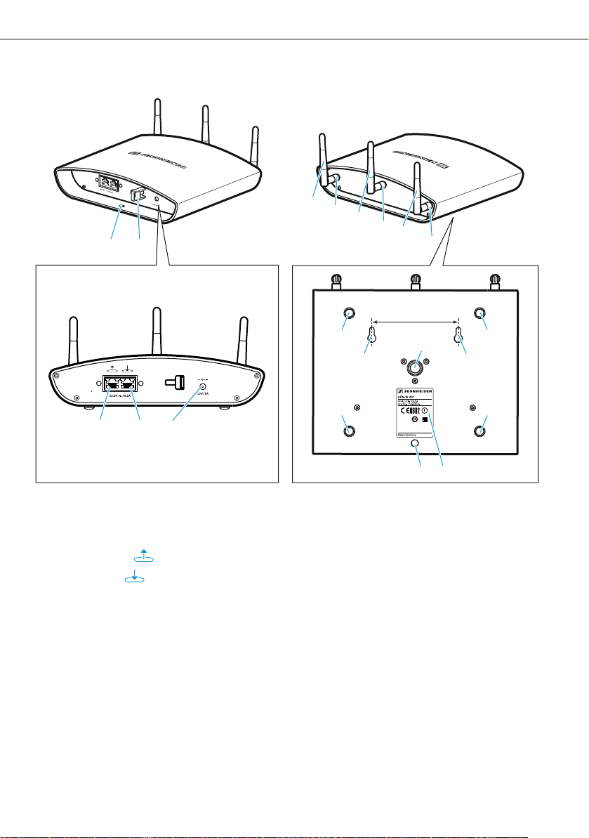
Product overview ADN-W AM
1
2
3
4
5
6
7
8
9
>
A
Product overview ADN-W AM
1
2
6
7
:
6
8
7
6
95 mm
9
7
:
8
4
3
Hole for safety wire
Cable grip
Output socket
Input socket
Hollow jack socket for connection of
optional NT 12-50C power supply
Antennas
4|ADN-W AM
5
:
1 A
Antenna coupling ring
Mounting holes for wall mounting
5/8" mounting thread
with 3/8" thread insert
Rubber feet
Type plate
:
Page 6
ENFRESRUNL ITJADA ZHFINO SV DE
Preparing the antenna module for operation
6
7
6
7
Preparing the antenna module for operation
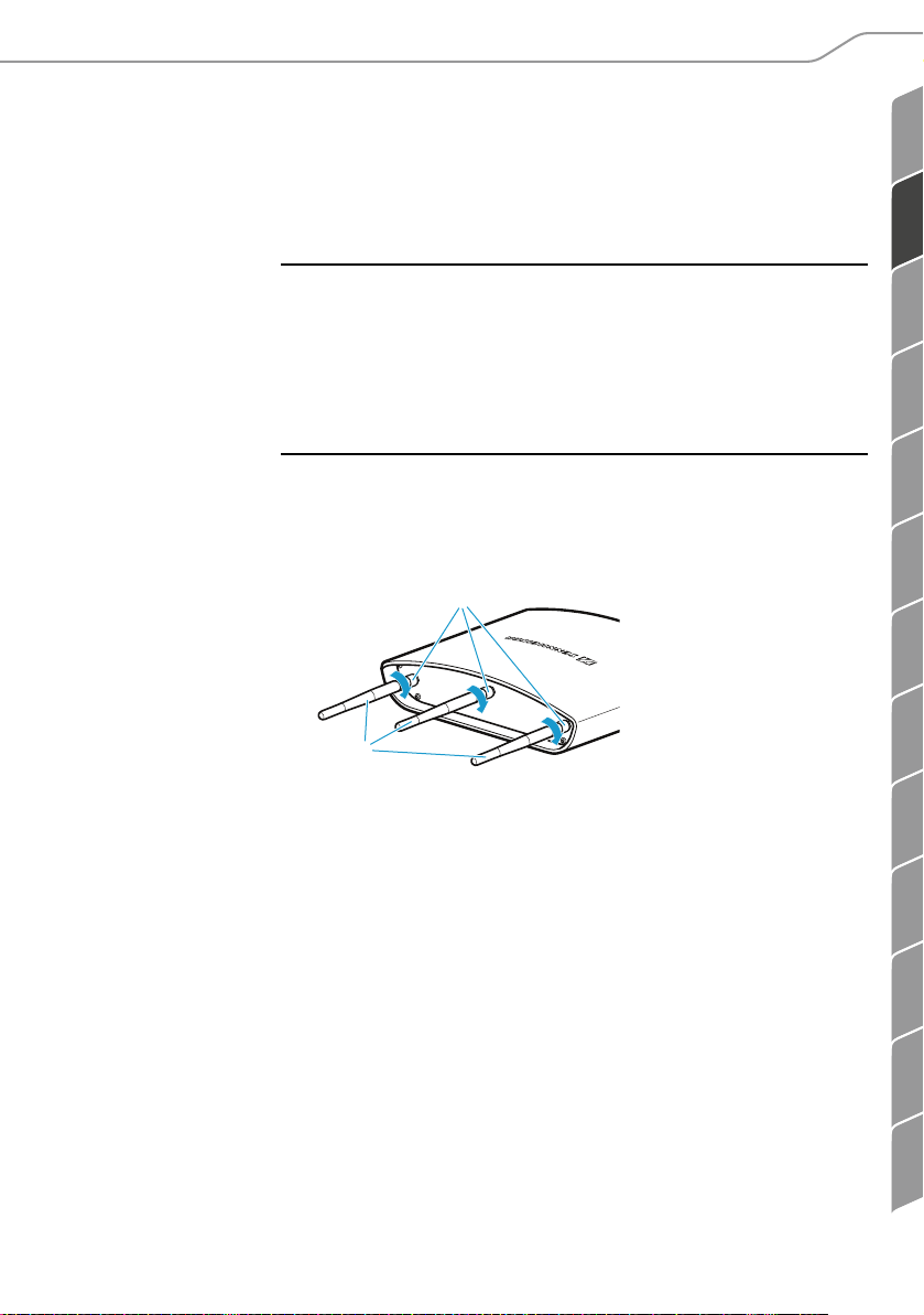
Connecting the antennas
Always use all 3 antennas to ensure reliable wireless operation. The
3 antennas are connected upon delivery.
CAUTION
Radio communication outside the legal requirements!
When connecting antennas other than the supplied ones, the transmission power of the conference system may not meet the legal
requirements and may cause interference to other radio equipment.
왘 Only connect the supplied rod antennas to the antenna module.
왘 Connect the 3 antennas to the 3 antenna sockets.
왘 Screw down the 3 antenna coupling rings as shown.
The antennas are connected and secured.
ADN-W AM
|5
Page 7

Preparing the antenna module for operation
Software Version Info
Main menu
System menu
Versions
No
Hardware Version Info
CU1 SB: 1
ADN PS: 1
AM 1
2
5
EU
UK
US
5
NT 12-50C
2
3
2
2
3
Connecting the antenna module to the mains power supply
The antenna module is powered from the ADN CU1 central unit via the
SBC CBL RJ45 system cable.
If the power supplied via the system cable is not sufficient and
if the antenna module is not listed in the central unit‘s operating menu under “
Version Info
왘 Use the optional NT 12-50C power supply.
CAUTION
Product damage due to an unsuitable power supply!
If you use an unsuitable power supply, this can cause damage to the
ADN-W AM antenna module.
왘 Only connect the NT 12-50C power supply to the antenna module.
왘 Connect the hollow jack plug of the NT 12-50C power supply to
the hollow jack socket .
System Menu” > “Versions” > “Hardware
” or “Software Version Info”:
6|ADN-W AM
왘 Pass the cable through the cable grip as shown.
왘 Connect the Euro 8 connector of the mains cable to the socket of
the NT 12-50C power supply.
왘 Connect the mains plug of the mains cable to a wall socket.
Page 8

ENFRESRUNL ITJADA ZHFINO SV DE
Setting up and positioning the antenna module
Setting up and positioning the
antenna module
The antenna module can be:
• mounted to a wall or ceiling by means of a ball joint (optional
accessory),
• mounted to a stand or
• placed on a flat surface (e.g. table)
CAUTION
Danger of injury and material damage!
If improperly installed or insufficiently fixed, the
antenna module can fall from the wall, ceiling or stand or
tip over and can cause injury or material damage.
왘 Protect the antenna module against tipping or drop-
ping by means of a safety wire which is attached to
a separate hook.
왘 Always have the antenna module mounted by a qual-
ified specialist according to local, national and international regulations and standards.
Further information on mounting the antenna module can be
found in the ADN system manual.
ADN-W AM
|7
Page 9

Setting up and positioning the antenna module
75
...
max. 50 m
ADN CU1
ADN-W AM
> 1 m
> 0.5 m
> 0.5 m
Transmission range approx. 30 m
> 0.5 m
ADN CU1
ESC
90°
CAUTION
Danger of intermodulation!
If you set up the antenna module and the wireless conference units too
close to one another, intermodulation can occur.
왘 Observe a minimum distance:
– of 1 m between the antenna module and the wireless conference
units and
– of 0.5 m between the wireless conference units.
The transmission range of the antenna module and the wireless conference units is approx. 30 m. The transmission range can vary
depending on location and environmental conditions such as wall
thickness, wall composition etc.
In some countries/regions (e.g. Canada), the use of wireless
components operating in the 5.15 to 5.25 GHz frequency band
(channel 5 to 8) is restricted to indoor use.
8|ADN-W AM
왘 Do not obstruct the antennas of the antenna module and the wire-
less conference units with any object.
왘 Set up the devices so that there is a “free line of sight” between the
wireless conference units and the antenna module.
왘 Place the antenna module as centrally as possible and above the
wireless conference units.
왘 Orient the 3 antennas of the antenna module so that they are par-
allel to each other and are directed at a 90° angle towards the wireless conference units.
Page 10

ENFRESRUNL ITJADA ZHFINO SV DE
Setting up and positioning the antenna module
< 10 m
> 10 m
We recommend using several antenna modules in rooms with
obstacles.
Ceiling mounting is recommended for rooms with a ceiling height of up
to approx. 10 m:
왘 Mount the antenna module to the center of the ceiling.
왘 Orient the antennas horizontally and at a 90° angle with respect to
the wireless conference units.
Wall mounting is recommended for rooms with a ceiling height of more
than 10 m because the wireless conference units have an omni-direc-
tional radiation pattern (approx. 30 m):
왘 Mount the antenna module to the wall at a height of max. 10 m
from the floor.
왘 Attach the antenna module upside down so that the antennas
point downwards.
왘 Slightly turn the antennas so that they are directed at a 90° angle
towards the wireless conference units.
ADN-W AM
|9
Page 11

Setting up and positioning the antenna module
To minimize restrictions in the transmission range:
왘 Avoid placing the antenna module outside the conference room,
behind support columns or boardings or next to other radio
equipment.
If necessary, use several antenna modules in order to provide
optimal antenna coverage.
10|ADN-W AM
Page 12

ENFRESRUNL ITJADA ZHFINO SV DE
Connecting the ADN-W AM antenna module to the ADN CU1 central unit
894
3
4
Connecting the ADN-W AM antenna module
to the ADN CU1 central unit
왘 Use a system cable (supplied with the ADN-W AM; the maximum
cable length allowed is 50 m) to connect the PORT II socket or
PORT I socket of the ADN CU1 central unit to the input
socket of the antenna module.
If the power supplied to the antenna module via the system
cable is not sufficient (the antenna module does not switch on),
you have to power the antenna module using the NT 12-50C
power supply (see page 6).
Optionally, you can also connect the antenna module to the
PORT sockets of an ADN PS power supply. It does not matter if
you are using a string or ring topology. The antenna module is
connected just like a conference unit to the cable string or cable
ring.
ADN CU1
IN –– AUDIO –– OUT
PORT II PORT I
2x 52.8V 1.75A
8 9
PORT II PORT I
100-240V~
50/60Hz 240W
ADN-W AM
3
4
To optionally combine the antenna module with wired conference
units, connect the antenna module just like a wired conference unit:
왘 Use a system cable to connect the output socket of the
antenna module to the IN socket of an ADN D1 or ADN C1 wired
conference unit.
Or:
왘 Use a system cable to connect the OUT socket of an ADN D1 or
ADN C1 wired conference unit to the input socket of the
antenna module.
ADN-W AM
|11
Page 13

Switching the antenna module on/off
ADN CU1
PORT I/PORT II
1 2
ADN PS
PORT I/PORT II PORT I/PORT II
1 2 1 2
ADN PS
OUT
IN
20
...
OUT
IN
20
...
OUT
IN
20
...
1
4
1
Switching the antenna module on/off
The antenna module is connected to the ADN CU1 central unit and
automatically switches on when the central unit is switched on.
To switch the antenna module on:
왘 Set the on/off switch of the ADN CU1 central unit to position “I”.
The central unit switches on and its display panel lights up. The
connected ADN-W AM antenna module is also switched on.
12|ADN-W AM
ADN CU1
ADN CU1
ESC
1
To switch the antenna module
ON
ADN-W AM
ON
off:
왘 Disconnect the system cable from the input socket of the
antenna module.
Or:
왘 Set the on/off switch of the ADN CU1 central unit to position “0”.
The antenna module is switched off. The wireless conference units
try to reconnect to the antenna module and automatically switch
off after 5 minutes if no switched-on antenna module can be
found.
Page 14

ENFRESRUNL ITJADA ZHFINO SV DE
Configuring the wireless components
Configuring the wireless components
CAUTION
Risk of violation of legal requirements!
If you are using radio frequencies and transmission powers that cannot
be used license-free in your country, there is a risk of violation of legal
requirements.
왘 Use only radio frequencies and transmission powers that are
approved and legal in your country.
왘 In the menu bar of the central unit‘s operating menu, click “Wireless
Menu” > “Country” and select the correct country/region in which
the conference system is to be used (see the ADN system manual).
For wireless conferencing, you have to configure the wireless components in order to adapt the radio settings to the legal requirements of
your country and to the requirements of your conference.
For configuring the wireless components, you can either use the central
unit’s operating menu or the “Conference Manager” software.
However, the full functionality of a wireless conference system can
only be configured using the software in “Live” operating mode.
In some countries/regions (e.g. Canada), the use of wireless
components operating in the 5.15 to 5.25 GHz frequency band
(channel 5 to 8) is restricted to indoor use.
Adjusting the radio settings
1. Select the country/region in which the conference system is to be
Wireless Menu” > “Country”).
used (“
The conference system only uses the radio settings that are
approved and legal in the selected country/region.
2. Select dynamic frequency management (“Wireless Menu” >
Channel Selection” > “Automatic”).
“
All radio settings are made automatically. The conference system
automatically detects occupied frequencies and switches to an
unused frequency band in case of interference.
3. Select the access mode for the wireless conference units:
– Open access mode (“
“Open”)
All ADN-W D1 wireless conference units that are ready for
operation automatically connect to the antenna module and
can be used instantly. This access mode should be used if only
one wireless conference system is in use and if the default
eavesdropping protection is sufficient.
Wireless Menu” > “Access mode” >
ADN-W AM
|13
Page 15

Cleaning and maintaining the antenna module
– Closed access mode (“Wireless Menu” > “Access Mode” >
“Closed”)
y wireless conference units whose serial numbers are listed in
Onl
a participant list can be used in the wireless conference. If several
wireless conferences are held simultaneously, the closed access
mode ensures that the wireless conference units connect to the
correct conference system. This access mode increases the protection against eavesdropping because only selected and
enabled wireless conference units can be used.
Further information on how to configure the wireless conference components can be found in the ADN system manual.
Cleaning and maintaining the
antenna module
왘 Only use a dry and soft cloth to clean the product.
Specifications ADN-W AM
RF frequency range 2.4 GHz; 5.1 to 5.9 GHz
RF output power 25 to 100 mW (depending on the selected
Power supply 12 to 15 V
Power co
Antennas 3 rod antennas with R-SMA connection
Transmission range typ. 30 m
Mounting thread 5/8" and 3/8" thread insert
Temperature range operation: +5°C to +45°C
Relative humidity operation: 20 to 95%
Dimensions (W x H x D) approx. 226 x 181 x 58 mm
Weight approx. 1,660 g
nsumption 6 W
country/region)
alternatively via ADN PORT bus 52.8 V
storage: -25°C to +70°C
storage: 10 to 90%
14|AD
N-W AM
Page 16

ENFRESRUNL ITJADA ZHFINO SV DE
Specifications ADN-W AM
In compliance with
Europe EMC EN 301489-1/-17
Radio EN 300328
EN 301893
EN 300440-1/-2
Safety EN 60065
Approved by
USA 47 CFR Part 15
FCC ID: DMOADNWAM
Canada
Japan Japanese Radio Law and Japanese Telecommu-
202-SMA057
D 12-0044 202
Brazil 3935-15-7356
CAN ICES-3(B)/NMB-3(B)
Industry Canada RSS 210
IC: 2099A-ADNWAM
nications Business Law Compliance
This device is granted pursuant to the
Japanese Radio Law ( 電波法) and the Japanese
Telecommunications Business Law ( 電気通信事
業法 ). This device should not be modified (otherwise the granted designation number will
become invalid)
CE Declaration of Conformity
RoHS Directive (2011/65/EU)
Radio Eq
uipment Directive (2014/53/EU)
The declaration is available at
www.sennheiser.com/download.
Before putting the product into operation,
please observe the respective country-specific
regulations.
Italy: For private use, a general authorization
for the frequency band 5150 - 5725 MHz is
required if our wireless system is used
outside own premises.
For public use, a general authorization is
required.
ADN-W AM|15
Page 17

Specifications ADN-W AM
Statements regarding the FCC and Industry Canada rules
This device complies with part 15 of the FCC rules and RSS-210 of Industry
Canada. Operation is subject to the following two conditions: (1) this device
may not cause harmful interference, and (2) this device must accept any interference received, including interference that may cause undesired operation.
The device for operation in the band 5150-5250 MHz is only for indoor use to
reduce the potential for harmful interference to co-channel mobile satellite
systems.
This equipment has been tested and found to comply with the limits for a Class
B digital device, pursuant to part 15 of the FCC Rules. These limits are designed
to provide reasonable protection against harmful interference in a residential
installation. This equipment generates, uses and can radiate radio
frequency energy and, if not installed and used in accordance with the instructions, may cause harmful interference to radio communications. However,
there is no guarantee that interference will not occur in a particular installation. If this equipment does cause harmful interference to radio or television
reception, which can be determined by turning the equipment off and on, the
user is encouraged to try to correct the interference by one or more of the following measures:
• Reorient or relocate the receiving antenna.
• Increase the separation between the equipment and receiver.
• Connect the equipment into an outlet on a circuit different from that to
which the receiver is connected.
• Consult the dealer or an experienced radio/ TV technician for help.
16|ADN-W AM
Changes or modifications not expressly approved by Sennheiser electronic
Corp. could void the user’s authority to operate the equipment.
This Class B digital apparatus complies with the Canadian ICES-003.
Radiofrequency radiation exposure Information:
This equipment complies with FCC radiation exposure limits set forth for an
uncontrolled environment. This equipment should be installed and operated
with minimum distance of 20 cm between the radiator and your body.
This transmitter must not be co-located or operating in conjunction with any
other antenna or transmitter.
Page 18

Sennheiser electronic GmbH & Co. KG
Am Labor 1, 30900 Wedemark, Germany
Publ. 08/16, 546420/A04
 Loading...