

Page 1
Instrucciones de uso
Bedienungsanleitung
Notice d’emploi
Instruction manual
Istruzioni per l’uso
Gebruiksaanwijzing
AC 3200-II
Active Transmitter Combiner 8:1
Page 2

Page 3

Inhalt
ENFRITNL ES DE
Inhalt
Wichtige Sicherheitshinweise .......................................................................................... 2
Active Transmitter Combiner 8:1 AC 3200-II ................................................................. 4
Lieferumfang ...................................................................................................................... 4
Anschluss-Schema ............................................................................................................. 5
Produktübersicht ............................................................................................................... 6
AC 3200-II in Betrieb nehmen .......................................................................................... 7
AC 3200-II für den Gebrauch vorbereiten ........................................................................ 7
Geräte anschließen ............................................................................................................... 9
Sender an den AC 3200-II anschließen ........................................................................... 10
Netzteil anschließen ........................................................................................................... 10
AC 3200-II ein- und ausschalten ...................................................................................... 11
Empfehlungen und Tipps für eine optimale Übertragung ......................................... 11
AC 3200-II reinigen und pflegen .................................................................................... 12
Wenn Störungen auftreten ............................................................................................ 12
Technische Daten ............................................................................................................. 14
Herstellererklärungen ..................................................................................................... 15
AC 3200-II | 1
Page 4

Wichtige Sicherheitshinweise
Wichtige Sicherheitshinweise
1. Lesen Sie diese Bedienungsanleitung.
2. Bewahren Sie diese Bedienungsanleitung auf. Geben Sie das Produkt an andere
Nutzer stets zusammen mit dieser Bedienungsanleitung weiter.
3. Beachten Sie alle Warnhinweise.
4. Befolgen Sie alle Anweisungen.
5. Verwenden Sie dieses Produkt nicht in der Nähe von Wasser.
6. Reinigen Sie das Produkt nur, wenn es nicht mit dem Stromnetz verbunden ist.
Verwenden Sie für die Reinigung ein trockenes Tuch.
7. Blockieren Sie keine Lüftungsöffnungen. Stellen Sie das Produkt nach den Anweisungen in dieser Bedienungsanleitung auf.
8. Stellen Sie das Produkt nicht in der Nähe von Wärmequellen wie Radiatoren, Öfen
oder anderen Wärme erzeugenden Apparaten (einschließlich Verstärkern) auf.
9. Betreiben Sie das Produkt ausschließlich an Stromquellentypen, die den Angaben
im Kapitel „Technische Daten“ (siehe Seite 14) und den Angaben auf dem Netzteil
entsprechen. Schließen Sie das Produkt stets an eine Steckdose mit Schutzleiter
an.
10. Achten Sie darauf, dass niemand auf das Netzkabel treten kann und dass es nicht
gequetscht wird, insbesondere nicht am Netzstecker, an der Steckdose und an
dem Punkt, an dem es aus dem Netzteil tritt.
11. Verwenden Sie nur die Zusatzgeräte/Zubehörteile, die Sennheiser empfiehlt.
12. Verwenden Sie das Produkt nur zusammen mit Wagen, Regalen,
Stativen, Halterungen oder Tischen, die der Hersteller angibt oder die
zusammen mit dem Produkt verkauft werden.
Wenn Sie einen Wagen verwenden, schieben Sie ihn zusammen mit
dem Produkt äußerst vorsichtig, um Verletzungen zu vermeiden und
zu verhindern, dass der Wagen umkippt.
13. Trennen Sie das Produkt vom Stromnetz, wenn Gewitter auftreten oder das Produkt über einen längeren Zeitraum nicht verwenden wird.
14. Lassen Sie alle Instandsetzungen von qualifiziertem Servicepersonal durchführen.
Instandsetzungen müssen durchgeführt werden, wenn das Produkt oder das
Netzkabel auf irgendeine Weise beschädigt wurde, Flüssigkeiten oder Objekte in
das Produkt gelangt sind, das Produkt Regen ausgesetzt war, es nicht fehlerfrei
funktioniert oder fallen gelassen wurde.
2 | AC 3200-II
Page 5
ENFRITNL ES DE
Wichtige Sicherheitshinweise
15. Ziehen Sie den Netzstecker aus der Steckdose, um das Produkt vom Stromnetz zu
trennen.
16. WARNUNG: Setzen Sie das Produkt weder Regen noch Feuchtigkeit aus.
Andernfalls besteht die Gefahr eines Brandes oder Stromschlages.
17. Setzen Sie das Produkt weder Spritz- noch Tropfwasser aus. Stellen Sie
keine mit Wasser gefüllten Gegenstände wie Blumenvasen auf das Gerät.
18. Achten Sie darauf, dass der Netzstecker des Netzkabels immer in ordnungsgemäßem Zustand und leicht zugänglich ist.
Bestimmungsgemäßer Gebrauch
Der bestimmungsgemäße Gebrauch des AC 3200-II schließt ein, dass Sie:
• das Gerät gewerblich einsetzen,
• dass Sie diese Bedienungsanleitung und insbesondere das Kapitel „Wichtige
Sicherheitshinweise“ ab Seite 2 gelesen und verstanden haben,
• dass Sie das Produkt innerhalb der Betriebsbedingungen nur so einsetzen wie in
dieser Bedienungsanleitung beschrieben.
Als nicht bestimmungsgemäßer Gebrauch gilt, wenn Sie das Produkt anders einsetzen, als es in dieser Bedienungsanleitung beschrieben ist, oder die Betriebsbedingungen nicht einhalten.
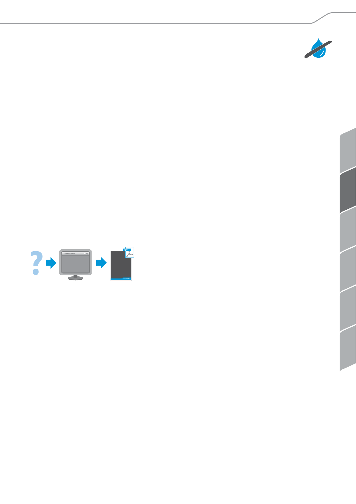
Diese Bedienungsanleitung steht Ihnen ebenfalls im Internet unter
www.sennheiser.com zur Verfügung.
www
Manual
AC 3200-II | 3
Page 6

Active Transmitter Combiner 8:1 AC 3200-II
Active Transmitter Combiner 8:1
An den AC 3200-II können Sie bis zu 8 Wireless-Monitoring-Sender der Marke
Sennheiser anschließen. Passende Sender finden Sie unter www.sennheiser.de auf der
Produktseite des AC 3200-II.
Sie benötigen dann lediglich eine einzige Antenne (Richtantenne A 2003 UHF, Rundstrahl-Antenne A 1031 U oder zirkular polarisierte UHF-Antenne A 5000 CP).
Damit erhalten Sie eine hochwertige Acht-Kanal-Audio-Übertragungsanlage für die
Einsatzzwecke:
• Mehrkanal-Wireless-Monitorsysteme für den Bühneneinsatz und
• Mehrkanalsysteme für den Talkback-Einsatz, z. B. in Studios.
AC 3200-II
Lieferumfang
1 Active Transmitter Combiner 8:1 AC 3200-II
1 Netzteil NT12-125D
3 Netzkabel (EU/UK/US)
4 selbstklebende Gerätefüße
1 Bedienungsanleitung
4 | AC 3200-II
Page 7
ENFRITNL ES DE
Anschluss-Schema
Stationäre Sender
AC 3200-II
ANT
RF OUTPUT
RF OUTPUTS
RF INPUTS
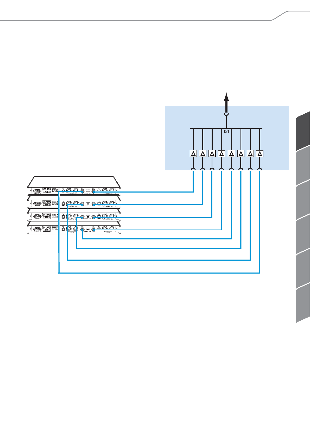
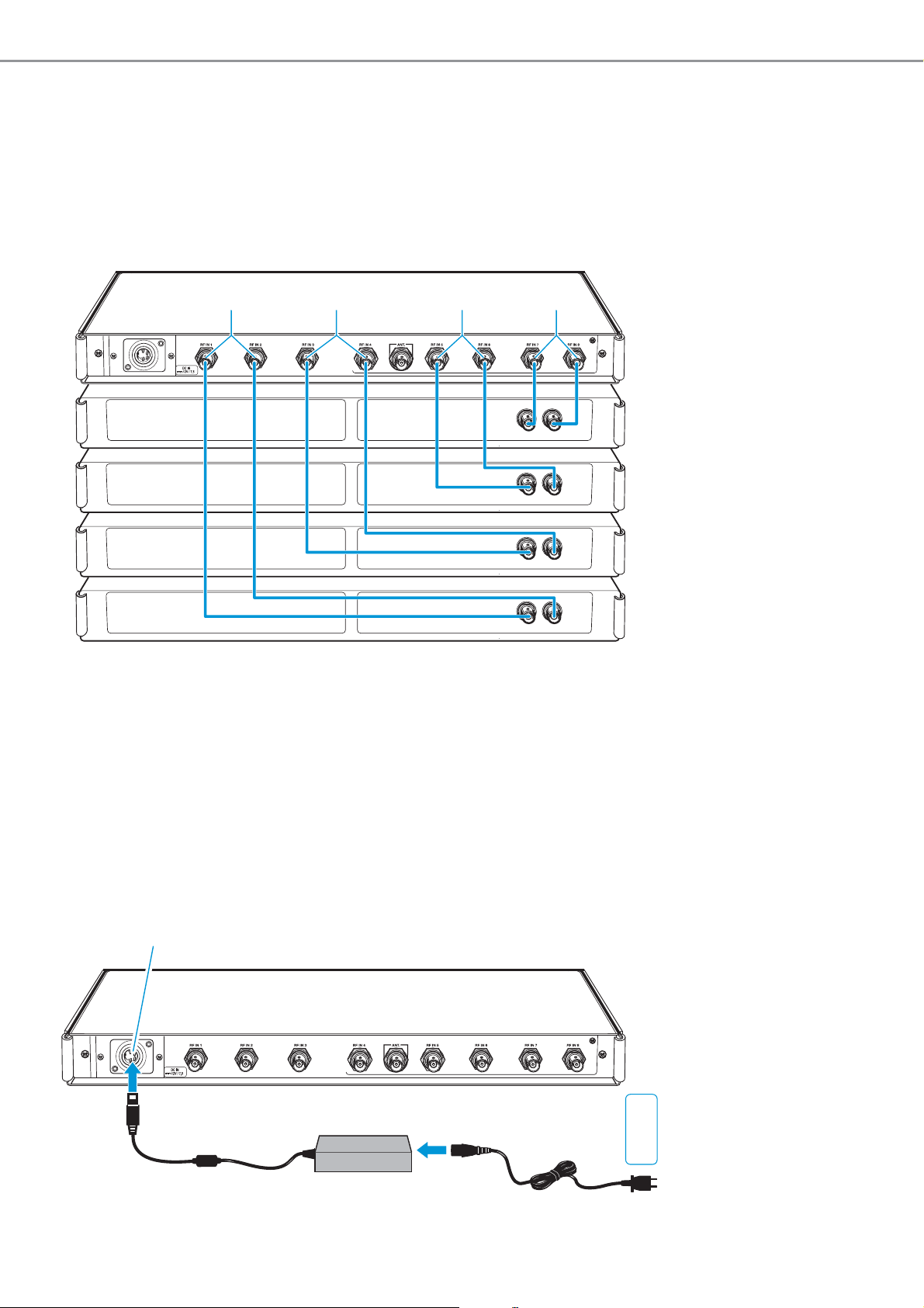
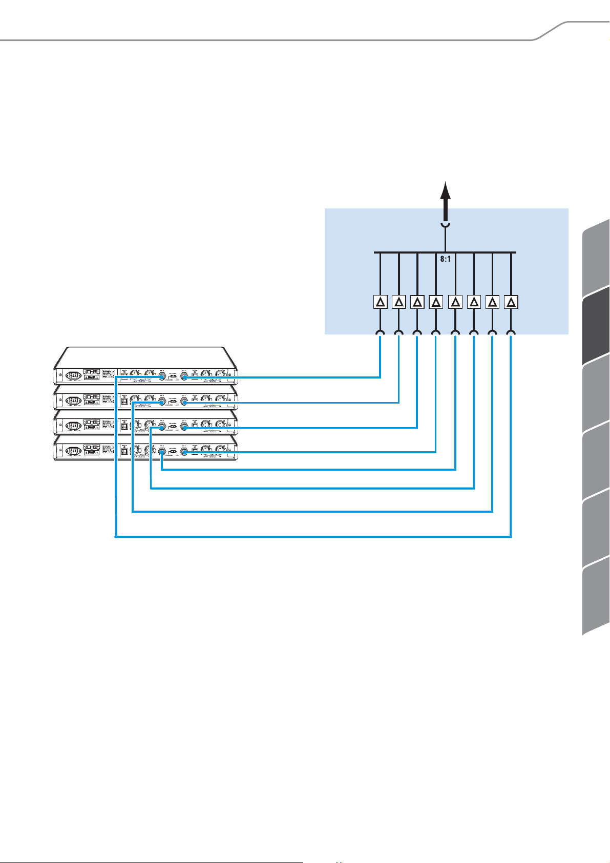
Anschluss-Schema
Das folgende Anschluss-Schema illustriert eine Acht-Kanal-Anlage mit nur einer
Antenne.
AC 3200-II | 5
Page 8

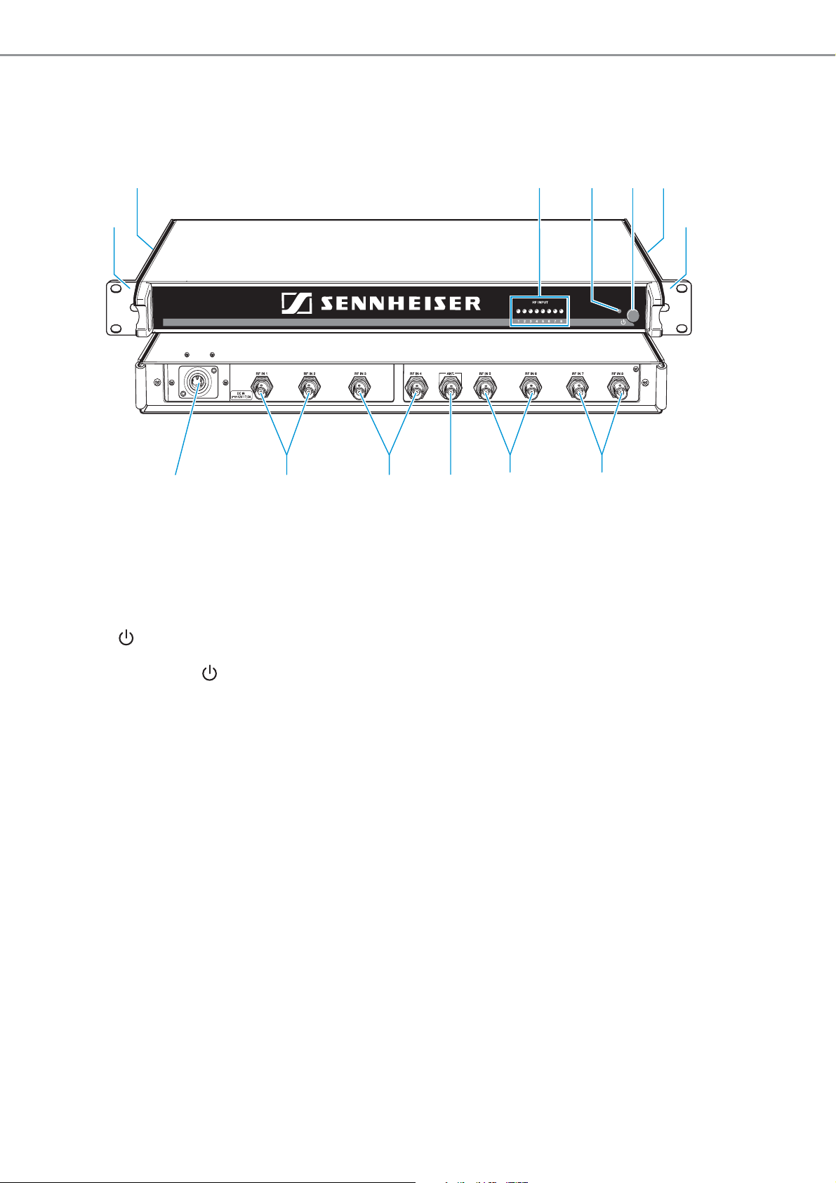
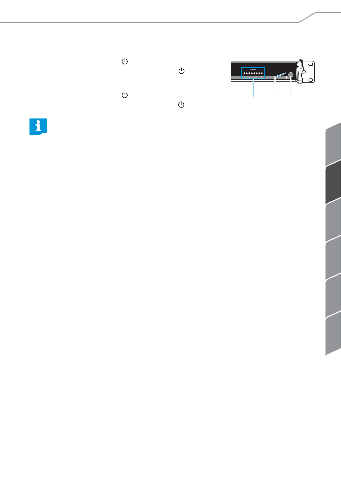
Produktübersicht
77
Produktübersicht
23452
1
ACTIVE TRANSMITTER COMBINER
AC 3200-II
1 Montagewinkel
2 Lüftungsöffnungen (seitlich)
3 8 LEDs: Betriebsanzeigen der HF-Eingänge
1
8776
4 LED
5 Ein-/Ausschalter
6 DC-Eingangsbuchse zum Anschluss des Netzteils NT 12-125D
7 8 HF-Eingänge RF IN 1 bis RF IN 8 zum Anschluss der Sender
8 BNC-Buchse für Antennenausgang ANT
6 | AC 3200-II
Page 9

ENFRITNL ES DE
AC 3200-II in Betrieb nehmen
AC 3200-II in Betrieb nehmen
AC 3200-II für den Gebrauch vorbereiten
Sie können den AC 3200-II entweder auf einer ebenen Fläche aufstellen oder in ein
Rack montieren.
Gerät aufstellen
VORSICHT
Gefahr von Geräteschäden durch Hitze
Der AC 3200-II sowie die angeschlossenen Sender entwickeln im Betrieb erhebliche
Abwärme. Wird diese nicht abgeführt, können die Geräte beschädigt werden.
Die Geräte enthalten teilweise Lüfter, um die entstehende Wärme abzutransportieren:
왘 Stellen Sie unbedingt sicher, dass die Luft ungehindert durch die seitlichen
Lüftungsöffnungen 2 des AC 3200-II und zwischen weiteren Geräten zirkulieren
kann.
왘 Reinigen Sie die seitlichen Lüftungsöffnungen regelmäßig mit einem weichen
Pinsel.
왘 Platzieren Sie den AC 3200-II als oberstes Gerät, um einen Wärmestau zu
verhindern.
왘 Stellen Sie niemals mehr als zwei Geräte direkt übereinander.
왘 Platzieren Sie mehrere Netzteile NT 12-125D nicht direkt nebeneinander.
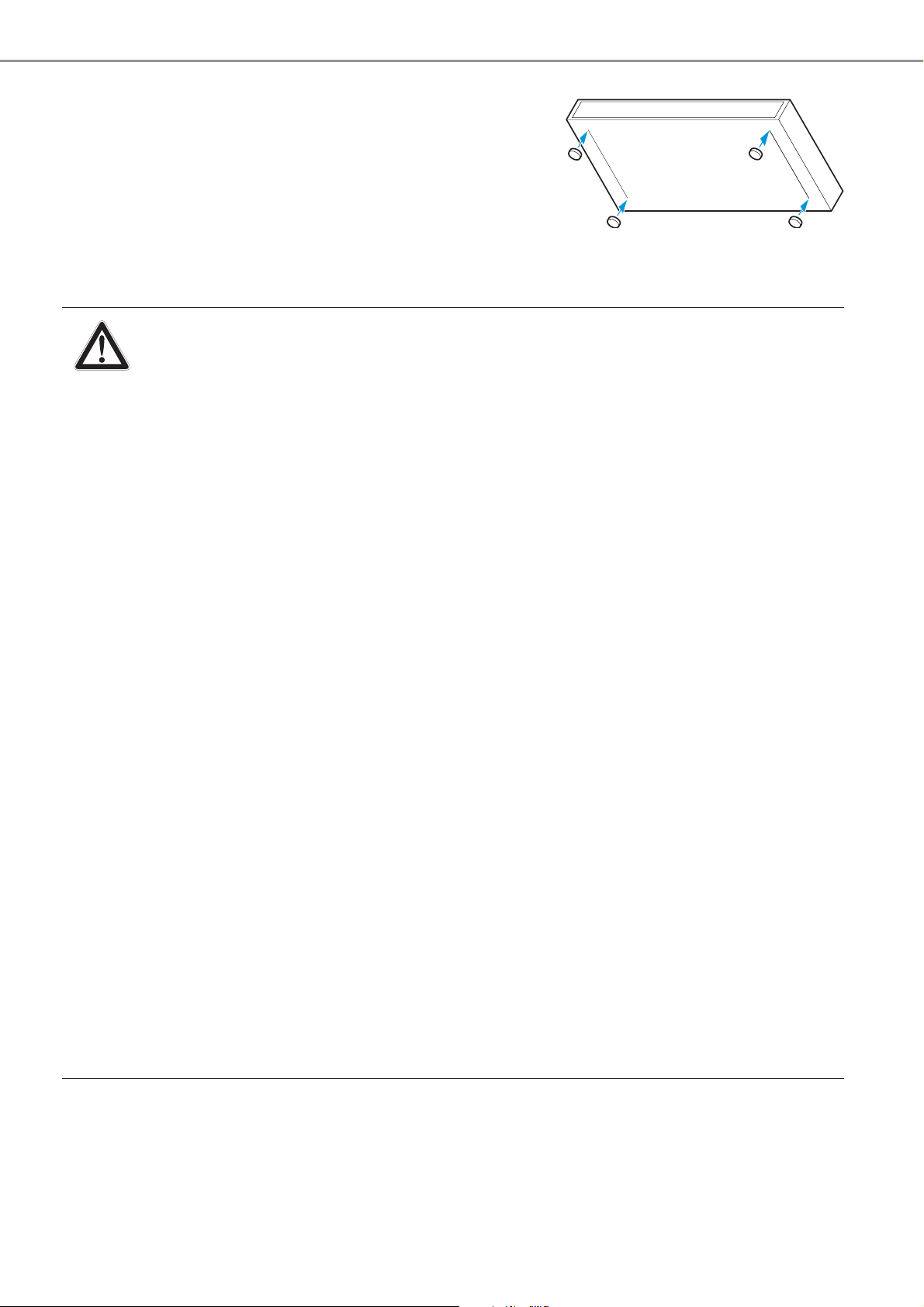
Damit der AC 3200-II rutschfest auf einer Unterlage steht, liegen vier selbstklebende
Gerätefüße aus Weichgummi bei.
VORSICHT
Gefahr der Verfärbung von Oberflächen
Oberflächen sind mit Lacken, Polituren oder Kunststoffen behandelt, die bei Kontakt
mit anderen Kunststoffen Flecken hervorrufen können. Wir können daher trotz sorgfältiger Prüfung der von uns eingesetzten Kunststoffe Verfärbungen Ihrer Oberflächen
nicht ausschließen.
왘 Stellen Sie den AC 3200-II nicht auf empfindliche Oberflächen.
왘 Reinigen Sie an der Unterseite des AC 3200-II die Stellen, an denen Sie die Geräte-
füße aufkleben möchten.
AC 3200-II | 7
Page 10
AC 3200-II in Betrieb nehmen
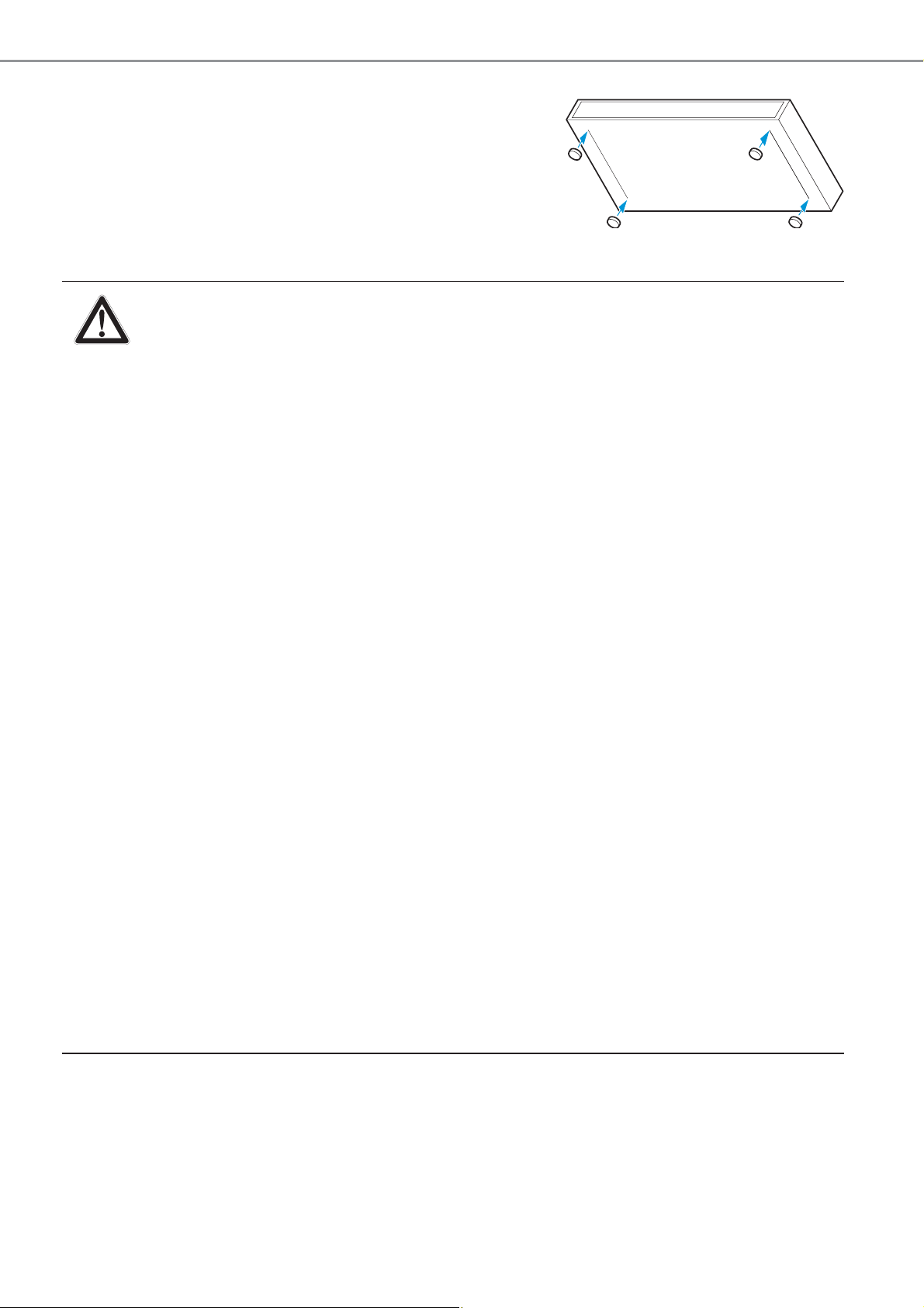
왘 Kleben Sie die Gerätefüße wie nebenstehend
abgebildet fest.
왘 Stellen Sie den AC 3200-II auf einer ebenen, waa-
gerechten Fläche auf.
Rack-Montage
VORSICHT
Gefahren bei der Rack-Montage
Beachten Sie beim Einbau des Geräts in ein geschlossenes Rack oder zusammen mit mehreren Geräten in ein Mehrfach-Rack, dass sich die Umgebungstemperatur, die mechanische Belastung und die elektrischen Potenziale
anders verhalten als bei Geräten, die nicht in ein Rack eingebaut werden:
왘 Die Umgebungstemperatur im Rack darf die in den technischen Daten vor-
gegebene Höchsttemperatur nicht überschreiten.
왘 Achten Sie beim Einbau in ein Rack darauf, dass die für den sicheren
Betrieb erforderliche Belüftung nicht beeinträchtigt wird oder sorgen Sie
für zusätzliche Belüftung.
왘 Platzieren Sie den AC 3200-II als oberstes Gerät im Rack, um einen Wärme-
stau zu verhindern.
왘 Lassen Sie eine Höheneinheit über dem AC 3200-II frei, damit die
erwärmte Luft entweichen kann.
왘 Platzieren Sie mehrere Netzteile NT 12-125D nicht direkt nebeneinander.
왘 Achten Sie beim Einbau in ein Rack auf gleichmäßige mechanische Belas-
tung, um Gefahr bringende Situationen zu vermeiden.
왘 Stellen Sie sicher, dass die beiden Kabel des Netzteils NT 12-125D keinen
mechanischen Belastungen (z. B. Zug) ausgesetzt sind.
왘 Beachten Sie beim Anschluss an das Stromnetz die Angaben auf dem
Netzteil. Vermeiden Sie eine Überlastung der Stromkreise. Sehen Sie bei
Bedarf einen Überstromschutz vor.
왘 Sorgen Sie durch geeignete Maßnahmen für die zuverlässige Erdung des
Geräts. Dies gilt besonders für Netzanschlüsse, die nicht direkt, sondern
z. B. über ein Verlängerungskabel erfolgen.
Um den AC 3200-II in ein 19’’-Rack zu montieren:
왘 Schieben Sie den AC 3200-II in das 19’’-Rack.
왘 Schrauben Sie die Montagewinkel 1 mit vier passenden Schrauben (nicht im
Lieferumfang enthalten) am Rack fest.
8 | AC 3200-II
Page 11
ENFRITNL ES DE
AC 3200-II in Betrieb nehmen
8
Geräte anschließen
Antenne anschließen
VORSICHT
Gefahr von Geräteschäden
Es ist nicht erlaubt, mehrere AC 3200-II zu kaskadieren oder andere Active Combiner
mit dem AC 3200-II zu verbinden.
왘 Schließen Sie den AC 3200-II niemals an andere Active Combiner an.
왘 Schließen Sie an den Ausgang des AC 3200-II ausschließlich geeignete Antennen
an.
Sie können eine Richtantenne A 2003 UHF, eine Rundstrahl-Antenne A 1031 U oder
eine zirkular polarisierte UHF-Antenne A 5000 CP anschließen. Die angeschlossene
Antenne überträgt die Signale aller angeschlossenen Sender (siehe Seite 11).
Beim Kombinieren der Signale auf einen Antennenausgang entstehen keine VerteilVerluste.
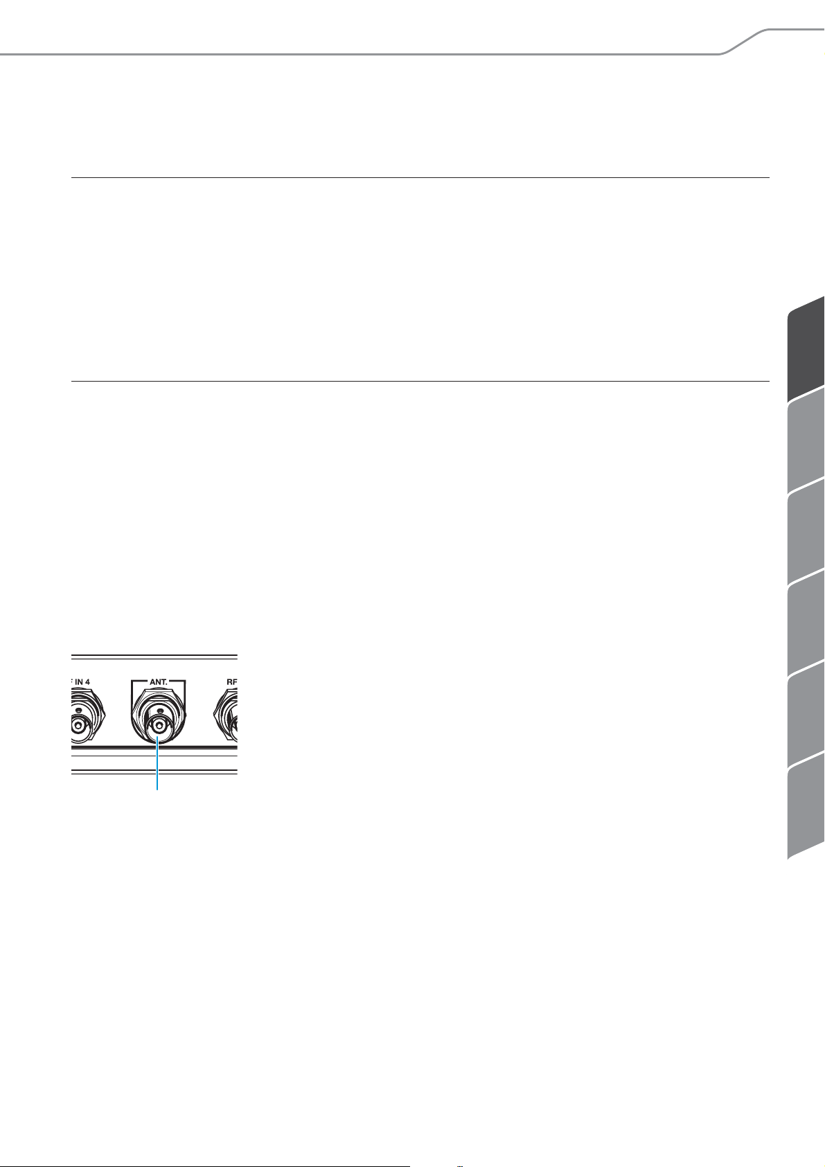
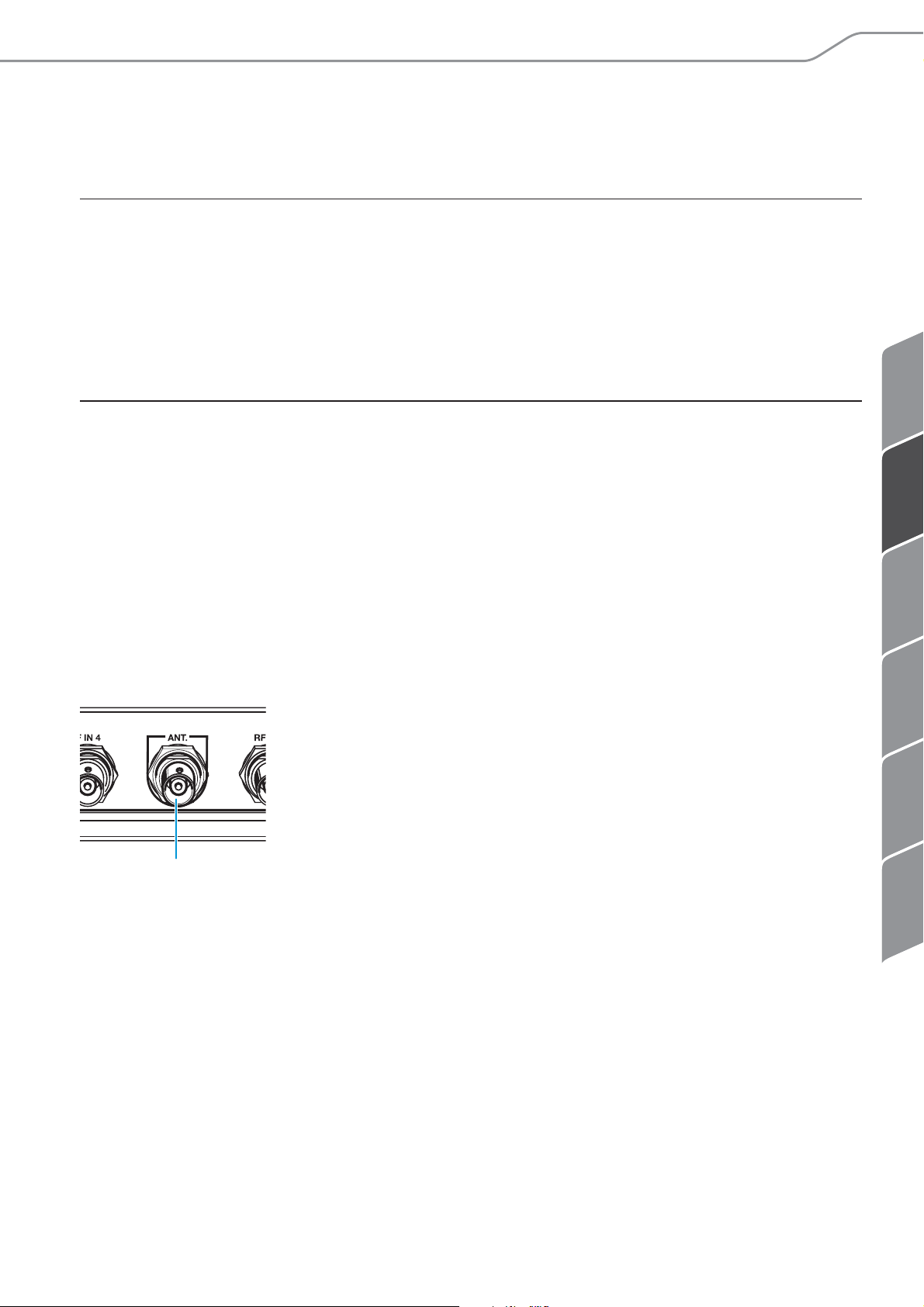
Um eine Antenne anzuschließen:
왘 Verbinden Sie die Antenne mit einem dämpfungsarmen 50-Ω-Koaxialkabel.
왘 Verbinden Sie das Koaxialkabel mit dem Antennenausgang 8.
AC 3200-II | 9
Page 12
AC 3200-II in Betrieb nehmen
77 77
UK
EU
US
6
NT 12-125D
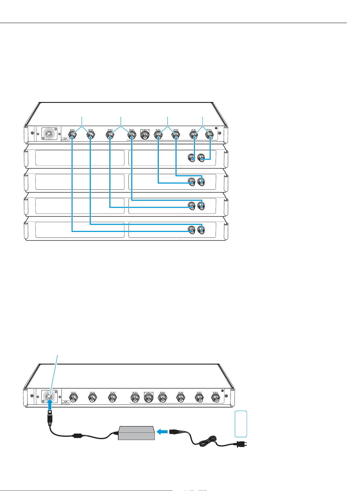
Sender an den AC 3200-II anschließen
Um einen Sender anzuschließen:
왘 Verbinden Sie das BNC-Kabel des Senders mit einem der acht HF-Eingänge RF IN 1
bis RF IN 8 7.
Netzteil anschließen
왘 Verbinden Sie das Netzkabel (je nach Region EU-, UK- oder US-Version) mit der
Eingangsbuchse am Netzteil NT 12-125D.
왘 Verbinden Sie den DC-Stecker des Netzteils mit der DC-Eingangsbuchse 6 des
AC 3200-II.
왘 Verbinden Sie den Netzstecker des Netzkabels mit dem Stromnetz.
10 | AC 3200-II
Page 13
ENFRITNL ES DE
Empfehlungen und Tipps für eine optimale Übertragung
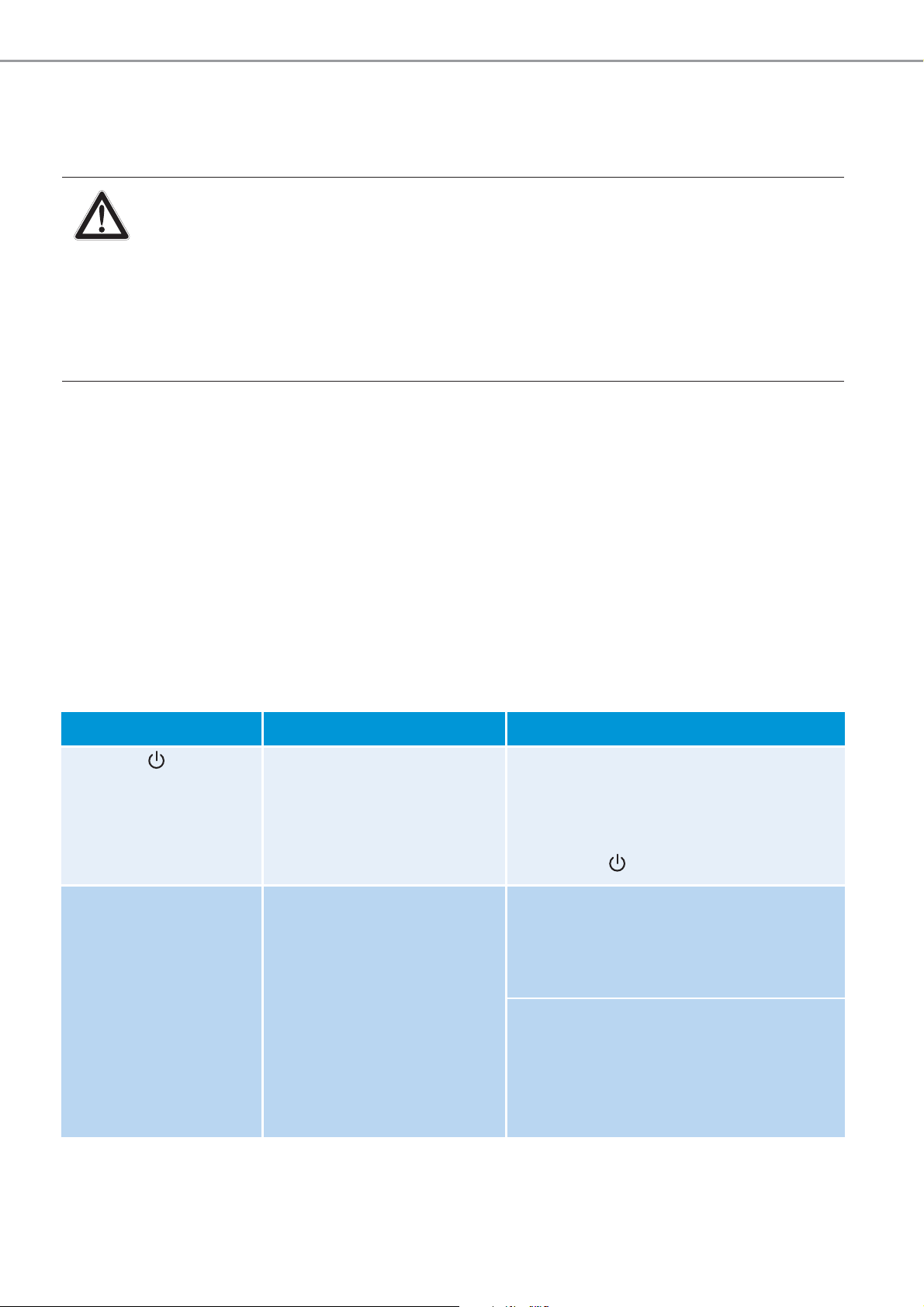
AC 3200-II ein- und ausschalten
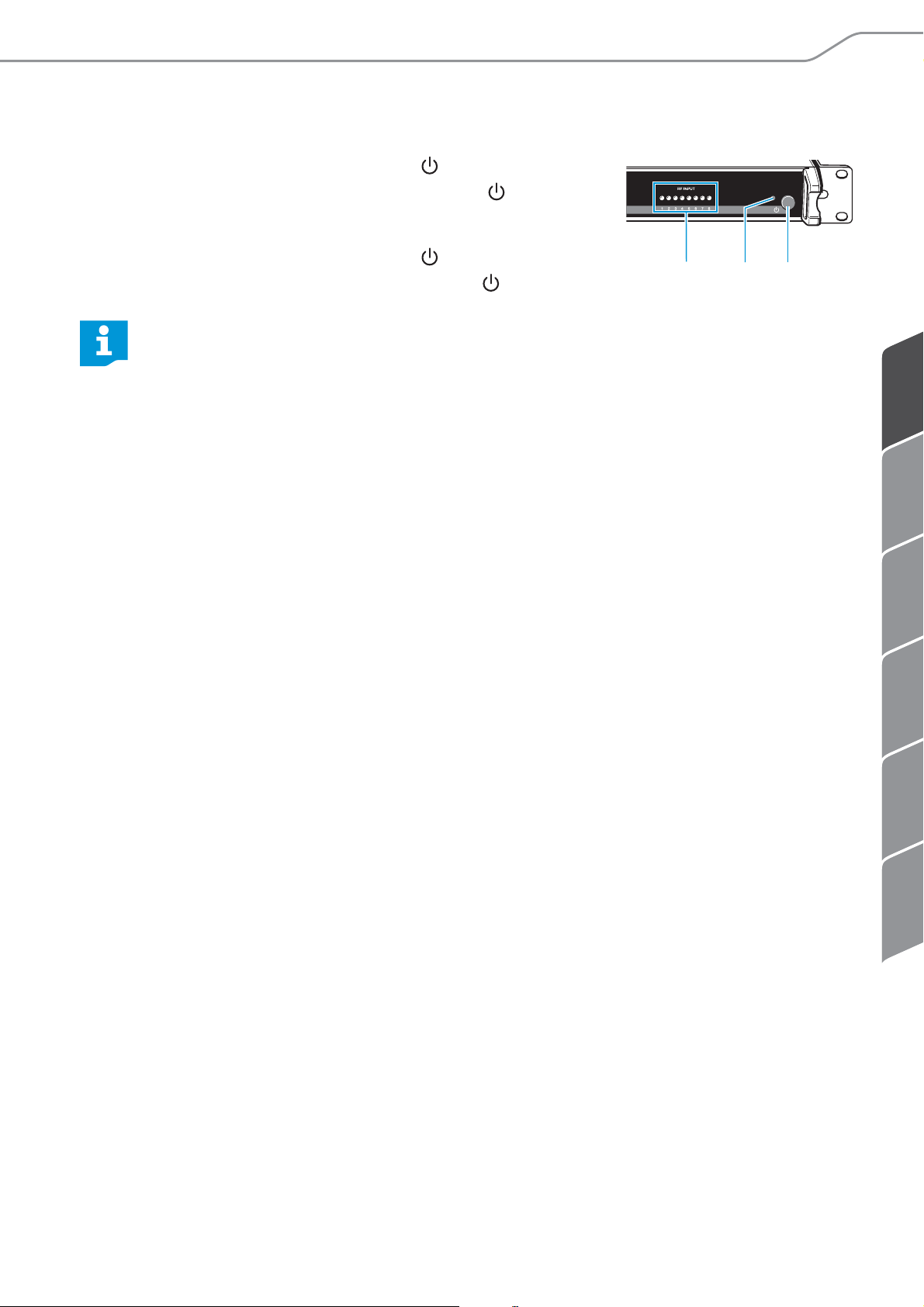
왘 Drücken Sie den Ein-/Ausschalter 5.
Der AC 3200-II schaltet sich ein, die LED 4 leuchtet
rot.
왘 Drücken Sie den Ein-/Ausschalter 5 erneut.
Der AC 3200-II schaltet sich aus, die LED 4 erlischt.
Nach dem Ausschalten befindet sich der AC 3200-II im Standby-Modus. Um
das Gerät und das Netzteil NT 12-125D vom Stromnetz zu trennen, ziehen Sie
den Netzstecker des Netzteils.
HF-Anzeige
Als zusätzliche Kontrolle verfügt der AC 3200-II über 8 LEDs 3. Diese leuchten an den
Kanälen grün auf, an denen Sendeleistung abgegeben wird.
34
5
Empfehlungen und Tipps für eine optimale
Übertragung
• Nach Möglichkeit sollten Sie für freie Sicht zwischen Sende- und Empfangs-
antennen sorgen.
• Halten Sie zwischen Sende- und Empfangsantennen den empfohlenen Mindest-
abstand von 5 m ein. Damit vermeiden Sie eine Funksignal-Übersteuerung des
Empfängers.
• Halten Sie zwischen der Sendeantenne und Stahl bzw. Beton den empfohlenen
Mindestabstand von 50 cm ein.
• Wenn Sie eine Multikanalanlage verwenden:
Stellen Sie alle Sender Ihrer Multikanalanlage auf intermodulationsfreie Frequenzen ein.
AC 3200-II | 11
Page 14
AC 3200-II reinigen und pflegen
AC 3200-II reinigen und pflegen
VORSICHT
Flüssigkeit kann die Elektronik des Geräts zerstören
Sie kann in das Gehäuse des Geräts eindringen und einen Kurzschluss in der
Elektronik verursachen.
왘 Halten Sie Flüssigkeiten jeglicher Art von dem Gerät fern.
왘 Verwenden Sie auf keinen Fall Löse- oder Reinigungsmittel.
왘 Trennen Sie das Netzteil NT 12-125D vom Stromnetz, bevor Sie mit der Reinigung
beginnen.
왘 Reinigen Sie das Produkt ausschließlich mit einem trockenen Tuch.
왘 Prüfen Sie regelmäßig, ob sich Staub in den Lüftungsöffnungen gesammelt hat,
und beseitigen Sie diesen ggf. mit einem weichen Pinsel.
Wenn Störungen auftreten
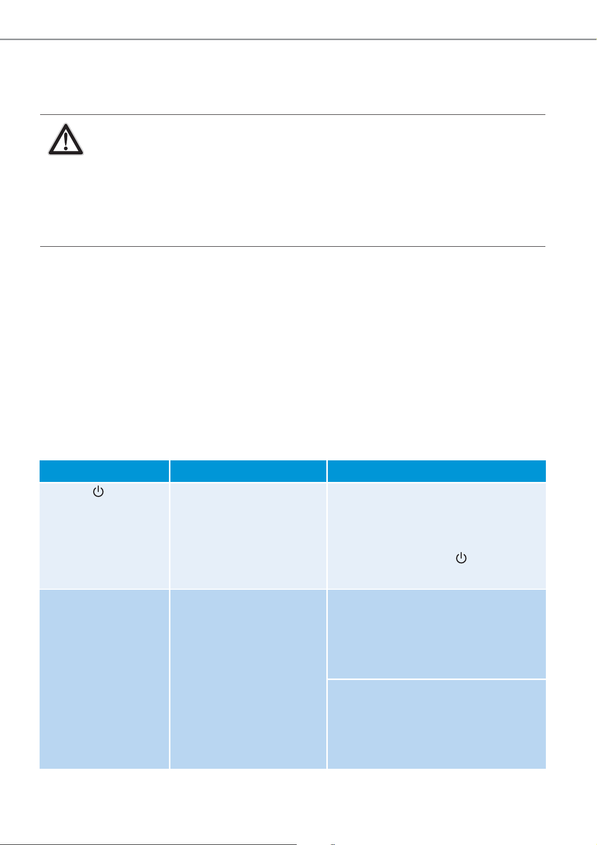
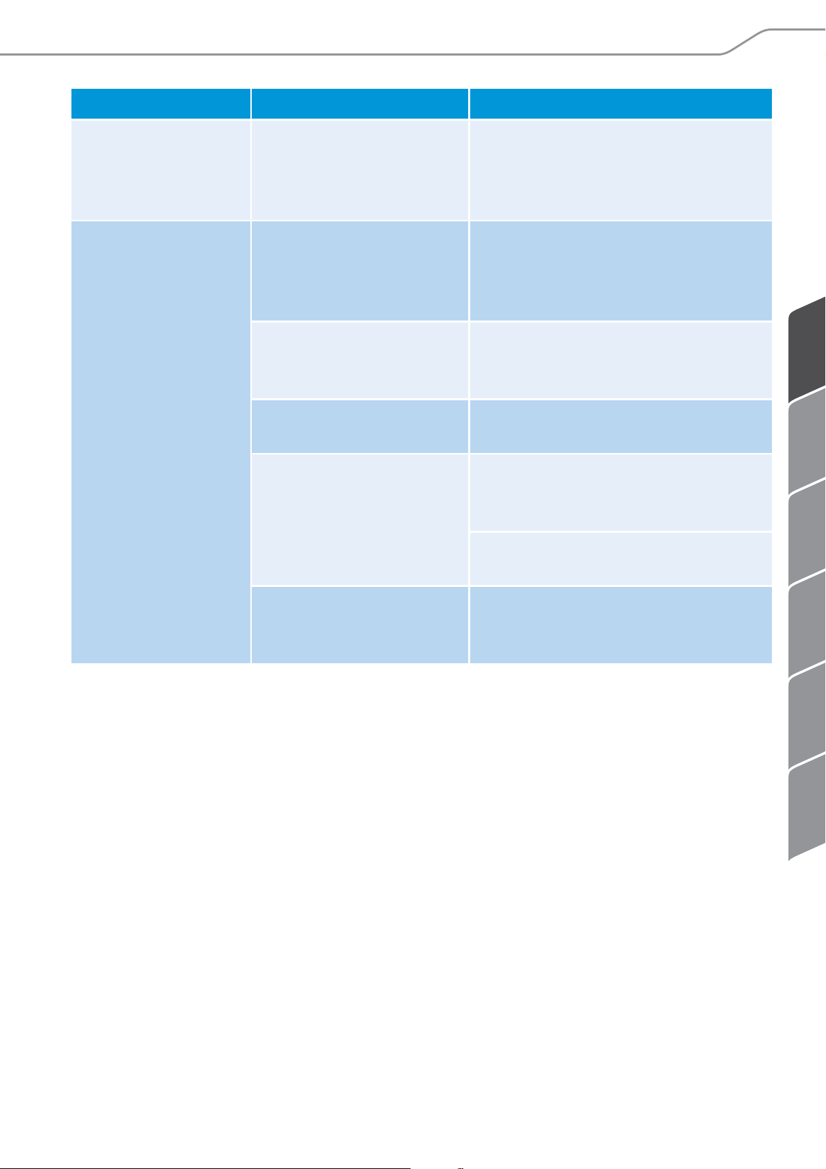
Problem Mögliche Ursache Abhilfe
Die LED 4
leuchtet nicht.
Betriebsanzeigen 3
bestimmter HFEingänge leuchten
auf, obwohl diese
nicht verwendet
werden
Das Gerät nimmt keinen
Strom auf.
Die Sendeantenne oder
das Antennenkabel ist
nicht angeschlossen,
vom falschen Typ,
beschädigt oder defekt.
Überprüfen Sie, ob der AC 3200-II
an das Netzteil NT 12-125D
angeschlossen ist, das Netzteil mit
dem Stromnetz verbunden ist und
der Ein-/Ausschalter 5 gedrückt
ist.
Stellen Sie sicher, dass die
Sendeantenne oder das
Antennenkabel angeschlossen
wurde, vom richtigen Typ und nicht
beschädigt oder defekt ist.
Stellen Sie sicher, dass die Antenne
oder das Antennenkabel an den
Antennenausgang 8 und die
Sender an die HF-Eingänge 7
angeschlossen wurden.
12 | AC 3200-II
Page 15
ENFRITNL ES DE
Wenn Störungen auftreten
Problem Mögliche Ursache Abhilfe
Eine oder mehrere
LEDs 3 leuchten
nicht.
Empfangsstörungen
bzw. kein Empfang
Am entsprechenden
Eingang ist ein Sender
angeschlossen,
dieser ist
jedoch ausgeschaltet.
Sendeantenne ist
außerhalb der
Reichweite der
Empfangsantennen
Batterien im Empfänger
sind nicht eingesetzt
oder leer
Antennen nicht korrekt
angeschlossen
zu hohe Kabeldämpfung
durch zu lange
Antennen
falscher Antennen
kabel oder
kabel-
Typ
Schalten Sie den Sender ein.
Verringern Sie den Abstand
zwischen Sender und Empfänger.
Tauschen Sie die Batterien aus.
Überprüfen Sie, ob die Antennen
richtig angeschlossen sind.
Verwenden Sie kürzere
Antennenkabel oder ein geeignetes
Antennenkabel.
Verwenden Sie ein dämpfungsarmes 50-Ω-Koaxialkabel.
Interferenzen oder
Intermodulationen im
Multikanalbetrieb
Stellen Sie alle Sender Ihrer
Multikanalanlage auf intermodulationsfreie Frequenzen ein.
Nehmen Sie Kontakt zu Ihrem Sennheiser-Partner auf, wenn mit Ihrer Anlage Probleme auftreten, die nicht in der Tabelle stehen, oder sich die Probleme nicht mit den in
der Tabelle aufgeführten Lösungsvorschlägen beheben lassen.
Den Partner Ihres Landes finden Sie auf www.sennheiser.com unter „Service &
Support“.
AC 3200-II | 13
Page 16

Technische Daten
Technische Daten
AC 3200-II
Frequenzbereich 500 bis 870 MHz
Verteildämpfung 0 dB (±1 dB)
HF-Eingangsleistung
Nennwert bis zu 100 mW je Eingang
Eingänge geschützt bis max. 250 mW
Impedanz 50 Ω
Spannungsversorgung 12 V
Stromaufnahme max. 7,5 A
Leistungsaufnahme max. 90 W
Temperaturbereich –10 °C bis +45 °C
Gewicht ca. 4 kg
Abmessungen 436 x 215 x 44 mm
NT 12-125D
Typ XP Power AHM150PS12
Eingangsspannung 100 bis 240 V
Eingangsfrequenz 50 bis 60 Hz
Stromaufnahme max. 1,8 A
Ausgangsspannung 12 V
Ausgangsstrom max. 12,5 A
Temperaturbereich 0 °C bis +45 °C
~
Gewicht ca. 760 g (ohne Netzkabel)
Abmessungen 204 x 78 x 38 mm
Länge des DC-Ausgangskabel ca. 93 cm/36 Zoll
14 | AC 3200-II
Page 17
ENFRITNL ES DE
Herstellererklärungen
0682
In Übereinstimmung mit
Europa EMV EN 301489-1/-9
Funk EN 300422-1/-2
EN 300454-1/-2
Sicherheit EN 60065
Zugelassen für
Kanada Industry Canada RSS-123
IC: 2099A-AC3200A2
limited to 698 MHz
USA FCC-Part 74
FCC ID: DMOAC3200A2
limited to 698 MHz
Herstellererklärungen
Garantie
Sennheiser electronic GmbH & Co. KG übernimmt für dieses Produkt eine Garantie von
24 Monaten.
Die aktuell geltenden Garantiebedingungen können Sie über das Internet
www.sennheiser.com oder Ihren Sennheiser-Partner beziehen.
In Übereinstimmung mit den folgenden Anforderungen
• RoHS Richtlinie (2002/95/EG)
CE-Konformität
•
• R&TTE Richtlinie (1999/5/EG)
Die Erklärung steht im Internet unter www.sennheiser.com zur Verfügung.
Vor Inbetriebnahme sind die jeweiligen länderspezifischen Vorschriften zu beachten.
AC 3200-II | 15
Page 18

Page 19

Contents
ENFRITNL ES DE
Contents
Important safety instructions ......................................................................................... 2
The AC 3200-II active transmitter combiner 8:1 ........................................................... 4
Delivery includes ................................................................................................................ 4
Connection diagram .......................................................................................................... 5
Product overview ............................................................................................................... 6
Putting the AC 3200-II into operation ............................................................................ 7
Preparing the AC 3200-II for use ....................................................................................... 7
Connecting devices ............................................................................................................... 9
Connecting a transmitter to the AC 3200-II .................................................................. 10
Connecting the mains unit ................................................................................................ 10
Switching the AC 3200-II on and off ............................................................................... 11
Recommendations and tips for optimum transmission ............................................ 11
Cleaning and maintaining the AC 3200-II .................................................................... 12
If a problem occurs ... ...................................................................................................... 12
Specifications ................................................................................................................... 14
Manufacturer Declarations ............................................................................................. 15
AC 3200-II | 1
Page 20

Important safety instructions
Important safety instructions
1. Read these instructions.
2. Keep these instructions. Always include these instructions when passing the
device on to third parties.
3. Heed all warnings.
4. Follow all instructions.
5. Do not use the device near water.
6. Clean only with a dry cloth.
7. Do not block any ventilation openings. Install in accordance with these
instructions.
8. Do not install near any heat sources such as radiators, heat registers, stoves, or
other devices (including amplifiers) that produce heat.
9. The device should be operated only from the type of power source indicated in the
chapter “Specifications” (see page 14) and on the mains unit. The device must
only be connected to properly grounded power outlets.
10. Protect the mains cable from being walked on or pinched, particularly at plugs,
convenience receptacles, and the point where it exits from the device.
11. Only use attachments/accessories specified by Sennheiser.
12. Use only with the cart, stand, tripod, bracket, or table specified by the
manufacturer, or sold with the device.
When a cart is used, use caution when moving the cart/apparatus
combination to avoid injury from tip-over.
13. Unplug the device during lightning storms or when unused for long periods of
time.
14. Refer all servicing to qualified service personnel. Servicing is required if the device
has been damaged in any way, such as mains cable or plug damage, liquid has
been spilled, objects have fallen inside, the device has been exposed to rain or
moisture, does not operate properly or has been dropped.
15. To completely disconnect the device from the AC mains, disconnect the mains plug
from the AC receptacle.
2 | AC 3200-II
Page 21
ENFRITNL ES DE
Important safety instructions
16. WARNING: To reduce the risk of fire or electric shock, do not expose the
device to rain or moisture.
17. Do not expose the device to dripping or splashing and ensure that no
objects filled with liquids, such as vases or coffee cups, are placed on the device.
18. The plug of the mains cable shall remain readily accessible.
Intended use
Intended use of the AC 3200-II includes:
• using the device for professional purposes,
• having read this instruction manual especially the chapter “Important safety
instructions” on page 2,
• using the device within the operating conditions and limitations described in this
instruction manual.
“Improper use” means using the device other than as described in this instruction
manual, or under operating conditions which differ from those described herein.
This instruction manual is also available on the Internet at www.sennheiser.com.
www
Manual
AC 3200-II | 3
Page 22

The AC 3200-II active transmitter combiner 8:1
The
With the AC 3200-II active transmitter combiner, the signals of up to eight Sennheiser
wireless monitoring transmitters can be combined onto a single antenna, e.g. the
A 2003 UHF directional antenna, the A 1031 U omni-directional antenna or the
A 5000 CP circularly polarized UHF antenna. For suitable transmitters, please refer to
the AC 3200-II product page at www.sennheiser.com.
The AC 3200-II allows you to make high-quality 8-channel transmission systems
suitable for the following areas of application:
• Multi-channel monitoring systems for stage use
• Multi-channel systems suitable for any application where talk-back signals are to
AC 3200-II active transmitter combiner 8:1
be transmitted (e.g. studio)
Delivery includes
1 AC 3200-II active transmitter combiner 8:1
1 NT12-125D mains unit
3 mains cables (EU/UK/US)
4 self-adhesive device feet
1 instruction manual
4 | AC 3200-II
Page 23
ENFRITNL ES DE
Connection diagram
Rack-mount transmitters
AC 3200-II
ANT
RF OUTPUT
RF OUTPUTS
RF INPUTS
Connection diagram
The below connection diagram shows the connections for an 8-channel system with a
single antenna.
AC 3200-II | 5
Page 24
Product overview
77
Product overview
23452
1
ACTIVE TRANSMITTER COMBINER
AC 3200-II
1 Rack mount “ears”
2 Air vents (on the sides)
3 8 LEDs: operation indicators of the RF inputs
1
8776
4 LED
5 On/off switch
6 DC input socket for connecting the NT 12-125D mains unit
7 8 RF inputs RF IN 1 to RF IN 8 for connecting the transmitters
8 BNC socket for antenna output ANT
6 | AC 3200-II
Page 25

ENFRITNL ES DE
Putting the AC 3200-II into operation
Putting the AC 3200-II into operation
Preparing the AC 3200-II for use
You can set up the AC 3200-II on an even surface or mount it into a rack.
Setting up the device
CAUTION
Danger of heat damage to the devices
During operation, the AC 3200-II and the connected transmitters produce
considerable waste heat. If this heat cannot dissipate, it can cause damage to the
devices.
The devices are equipped with fans to assist dissipation of generated heat:
왘 Make sure that the air vents 2 on the sides of the AC 3200-II are not covered or
blocked and provide ducts of sufficient size or allow sufficient space to ensure a free
air flow between the devices.
왘 Regularly clean the air vents on the sides of the AC 3200-II with a soft brush.
왘 In order to avoid heat accumulation, make sure to install the AC 3200-II as the
uppermost device.
왘 Never stack more than two devices directly one above the other.
왘 Never place several NT 12-125D mains units directly next to one another.
To ensure that the AC 3200-II cannot slip on the surface on which it is placed, four selfadhesive soft rubber feet are supplied.
CAUTION
Risk of staining of surfaces
Some surfaces have been treated with varnish, polish or synthetics which might cause
stains when they come into contact with other synthetics. Despite a thorough testing
of the synthetics used by us, we cannot rule out the possibility of staining.
왘 Do not place the AC 3200-II on delicate surfaces.
왘 Ensure that the base of the AC 3200-II is clean and free from grease before fitting
the rubber feet.
AC 3200-II | 7
Page 26
Putting the AC 3200-II into operation
왘 Fix the rubber feet to the base of the AC 3200-II
by peeling off the backing paper and fitting them
as shown in the diagram on the right.
왘 Place the AC 3200-II on an even, horizontal
surface.
Rack-mounting
CAUTION
Risks when rack mounting the AC 3200-II
When installing the device in a closed or multi-rack assembly, please consider
that, during operation, the ambient temperature, the mechanical loading and
the electrical potentials will be different from those of devices which are not
mounted into a rack:
왘 The ambient temperature within the rack must not exceed the
temperature limit specified in the AC 3200-II specifications.
왘 When installing the device in a rack, take good care not to affect the
ventilation required for safe operation. If necessary, provide additional
ventilation.
왘 In order to avoid heat accumulation, make sure to install the AC 3200-II as
the uppermost device in the rack.
왘 Provide for a duct or vent space of 1 U above the AC 3200-II to ensure that
the heated air can dissipate.
왘 Never place several NT 12-125D mains units directly next to one another.
왘 Make sure the mechanical loading of the rack is even to avoid a hazardous
condition such as a severely unbalanced rack.
왘 Make sure the two cables of the NT 12-125D mains unit are not exposed
to mechanical loading (e.g. pulling).
왘 When connecting the device to the power supply, observe the information
indicated on the mains unit. Avoid circuit overloading. If necessary, provide
overcurrent protection.
왘 Ensure a reliable mains ground connection of the device by taking
appropriate measures – especially when you are using multi-outlet power
strips or extension cables.
To mount the AC 3200-II into a 19’’ rack:
왘 Slide the AC 3200-II into the 19’’ rack.
왘 Secure the rack mount “ears” 1 to the rack using four screws (to be ordered
separately).
8 | AC 3200-II
Page 27
ENFRITNL ES DE
Putting the AC 3200-II into operation
8
Connecting devices
Connecting the antenna
CAUTION
Danger of damage to the devices!
Do not daisy-chain several AC 3200-II. Do not connect other active combiners to the
AC 3200-II.
왘 Never connect the AC 3200-II to other active combiners.
왘 Only connect suitable antennas to the output of the AC 3200-II.
The AC 3200-II active transmitter combiner can be used with either the A 2003 UHF
directional antenna, the A 1031 U omni-directional antenna or the A 5000 CP
circularly polarized UHF antenna. The antenna transmits the signals of all connected
transmitters (see page 11).
The signals are combined onto the antenna output with no distribution attenuation.
To connect an antenna:
왘 Connect the antenna using a low-attenuation 50-Ω coaxial cable.
왘 Connect the coaxial cable to the antenna output 8.
AC 3200-II | 9
Page 28
Putting the AC 3200-II into operation
77 77
UK
EU
US
6
NT 12-125D
Connecting a transmitter to the AC 3200-II
To connect a transmitter:
왘 Connect the BNC cable of the transmitter to one of the eight RF inputs RF IN 1 to
RF IN 8 7.
Connecting the mains unit
왘 Connect the mains cable (EU, UK or US version, depending on your location) to the
input socket on the NT 12-125D mains unit.
왘 Connect the DC connector of the mains unit to the DC input socket 6 of the
AC 3200-II.
왘 Connect the mains connector of the mains cable to the mains power supply.
10 | AC 3200-II
Page 29
ENFRITNL ES DE
Recommendations and tips for optimum transmission
Switching the AC 3200-II on and off
왘 Press the on/off switch 5.
The AC 3200-II switches on and the LED 4 lights up
red.
왘 Press the on/off switch 5 again.
The AC 3200-II switches off and the LED 4 goes off.
After switch-off, the AC 3200-II is in standby mode. To disconnect the device
and the NT 12-125D mains unit from the mains power supply, pull out the
mains connector from the wall socket.
RF indicators
The AC 3200-II has 8 control LEDs 3 which light up green on the channels where
transmission power is available.
34
5
Recommendations and tips for optimum
transmission
• There should be a “free line of sight” between transmitting and receiving
antennas.
• To avoid overloading the receiver, observe a minimum distance of 5 m between
transmitting and receiving antennas.
• Observe a minimum distance of 50 cm between the transmitting antenna and
metal objects (such as cross members or reinforced-concrete walls).
• When using a multi-channel system:
Set all transmitters of your multi-channel system to intermodulation-free
frequencies.
AC 3200-II | 11
Page 30
Cleaning and maintaining the AC 3200-II
Problem Possible cause Solution
Cleaning and maintaining the AC 3200-II
CAUTION
Liquids can damage the electronics of the device
Liquids entering the housing of the device can cause a short-circuit and
damage the electronics.
왘 Keep all liquids away from the device.
왘 Do not use any solvents or cleansing agents.
왘 Before cleaning, disconnect the NT 12-125D mains unit from the mains power
supply.
왘 Only use a dry cloth to clean the device.
왘 Regularly check the air vents for dust deposits. If necessary, remove the dust with
a soft brush.
If a problem occurs ...
The LED 4 does
not light up
Extra LEDs 3 light
up for RF inputs
which are not in use
The AC 3200-II doesn’t
consume current.
The transmitting
antenna or the antenna
cable is not connected,
of the wrong type,
damaged or faulty
.
Check if the AC 3200-II is connected
to the NT 12-125D mains unit, if
the mains unit is connected to the
mains power supply and if the on/
off switch 5 is pressed.
Check that the transmitting
antenna or the antenna cable is
correctly connected, of the correct
type, and is not damaged or faulty.
Check that the transmitting
antenna or the antenna cable
is connected to the antenna
output 8 and that all transmitters
are connected to RF inputs 7.
12 | AC 3200-II
Page 31

ENFRITNL ES DE
If a problem occurs ...
Problem Possible cause Solution
One or several
LEDs 3 do not light
up
Disturbed reception
or no reception
A transmitter is
connected to the
corresponding input
but the transmitter
is not switched on.
The transmitting
antenna is not within the
reception area.
The receiver batteries
are not inserted or
batteries are low.
The antenna is not
connected correctly.
Too high cable
attenuation due to too
long antenna cables or
wrong type of antenna
cable.
Switch the transmitter on.
Reduce the distance between
transmitter and receiver.
Replace the receiver batteries.
Check if the antenna is connected
correctly.
Use a shorter antenna cable or the
correct type of antenna cable.
Use low-attenuation 50 Ω coaxial
cable.
Interference or
intermodulation during
multi-channel operation.
Set all transmitters of your
multi-channel system to
intermodulation-free frequencies.
If a problem occurs that is not listed in the above table or if the problem cannot be
solved with the proposed solutions, please contact your local Sennheiser partner for
assistance.
To find a Sennheiser partner in your country, search at www.sennheiser.com under
“Service & Support”.
AC 3200-II | 13
Page 32

Specifications
Specifications
AC 3200-II
Frequency range 500 to 870 MHz
Distribution attenuation 0 dB (±1 dB)
RF input power
Nominal value up to 100 mW per input
Inputs protected up to max. 250 mW
Impedance 50 Ω
Power supply 12 V
Current consumption max. 7.5 A
Power consumption max. 90 W
Temperature range –10°C to +45°C
Weight approx. 4 kg
Dimensions 436 x 215 x 44 mm
NT 12-125D
Type XP Power AHM150PS12
Input voltage 100 to 240 V
Input frequency 50 to 60 Hz
Current consumption max. 1.8 A
Output voltage 12 V
Output current max. 12.5 A
Temperature range 0°C to +45°C
~
Weight approx. 760 g (without mains cable)
Dimensions 204 x 78 x 38 mm
Length of DC output cable approx. 93 cm/36 inch
14 | AC 3200-II
Page 33

ENFRITNL ES DE
Manufacturer Declarations
0682
In compliance with
Europe EMC EN 301489-1/-9
Radio EN 300422-1/-2
EN 300454-1/-2
Safety EN 60065
Approved by
Canada Industry Canada RSS-123
IC: 2099A-AC3200A2
limited to 698 MHz
USA FCC-Part 74
FCC ID: DMOAC3200A2
limited to 698 MHz
Manufacturer Declarations
Warranty
Sennheiser electronic GmbH & Co. KG gives a warranty of 24 months on this product.
For the current warranty conditions, please visit our website at www.sennheiser.com
or contact your Sennheiser partner.
In compliance with the following requirements
• RoHS Directive (2002/95/EC)
CE Declaration of Conformity
•
• R&TTE Directive (1999/5/EC)
The declaration is available on the Internet at www.sennheiser.com.
Before putting the device into operation, please observe the respective countryspecific regulations.
AC 3200-II | 15
Page 34

Manufacturer Declarations
Statements regarding FCC and Industry Canada
This device complies with Part 15 of the FCC Rules and with Industry Canada
Operation is subject to the following two conditions: (1) this
harmful interference, and (2) this device must accept any
including interference that may cause undesired operation.
This equipment has been tested and found to comply with the limits for a Class B
digital device, pursuant to Part 15 of the FCC Rules. These limits are designed to
provide reasonable protection against harmful interference in a residential
installation. This equipment generates, uses and can radiate radio frequency energy
and, if not installed and used in accordance with the instructions, may cause harmful
interference to radio communications. However, there is no guarantee that
interference will not occur in a particular installation. If this equipment does cause
harmful interference to radio or television reception, which can be determined by
turning the equipment off and on, the user is encouraged to try to correct the
interference by one or more of the following measures:
• Reorient or relocate the receiving antenna.
• Increase the separation between the equipment and receiver.
• Connect the equipment into an outlet on a circuit different from that to which the
receiver is connected.
• Consult the dealer or an experienced radio/TV technician for help.
Changes or modifications made to this equipment not expressly approved by
Sennheiser electronic Corp. may void the FCC authorization to operate this equipment.
Before putting the device into operation, please observe the respective countryspecific regulations!
16 | AC 3200-II
Page 35

Sommaire
ENFRITNL ES DE
Sommaire
Consignes de sécurité importantes ................................................................................. 2
Le combineur d’antenne actif 8:1 AC 3200-II ................................................................ 4
Contenu ............................................................................................................................... 4
Schéma de raccordement ................................................................................................. 5
Vue d’ensemble du produit .............................................................................................. 6
Mettre l’AC 3200-II en service .......................................................................................... 7
Préparer l’AC 3200-II pour l’utilisation ............................................................................. 7
Raccorder les appareils ........................................................................................................ 9
Raccorder un émetteur à l’AC 3200-II ............................................................................. 10
Raccorder le bloc secteur ................................................................................................... 10
Mettre l’AC 3200-II en marche/à l’arrêt ......................................................................... 11
Recommandations et conseils pour une transmission optimale .............................. 11
Nettoyage et entretien de l’AC 3200-II ........................................................................ 12
En cas d’anomalies .......................................................................................................... 12
Caractéristiques techniques ........................................................................................... 14
Déclarations du fabricant ............................................................................................... 15
AC 3200-II | 1
Page 36

Consignes de sécurité importantes
Consignes de sécurité importantes
1. Lisez cette notice d’emploi.
2. Conservez cette notice d’emploi et joignez-la toujours à l’appareil si vous remettez
ce dernier à un tiers.
3. Respectez tous les avertissements.
4. Respectez toutes les instructions.
5. N’utilisez pas cet appareil à proximité d’eau.
6. Ne nettoyez l’appareil qu’à l’aide d’un chiffon sec.
7. Ne bloquez pas les orifices d’aération. Installez l’appareil conformément aux
instructions de cette notice.
8. N’installez pas l’appareil à proximité de sources de chaleur, telles que des
radiateurs, registres de chaleur, fours ou autres appareils (y compris les
amplificateurs) générant de la chaleur.
9. Utilisez exclusivement l’appareil avec le tppe de source de courant indiqué dans le
chapitre « Caractéristiques techniques » (voir page 14) et sur le bloc secteur.
Branchez toujours l’appareil dans une prise munie d’un conducteur de protection.
10. Veillez à ce que personne ne puisse marcher sur le câble secteur ni l’écraser,
notamment au niveau de la fiche secteur, de la prise et au point de sortie de
l’appareil.
11. N’utilisez que les appareils supplémentaires/accessoires recommandés par
Sennheiser.
12. N’utilisez l’appareil qu’en conjonction avec des chariots, étagères,
statifs, supports ou tables indiqués par le fabricant ou vendus avec les
appareils.
En cas d’utilisation d’un chariot, poussez-le en même temps que les
appareils en faisant preuve d’une extrême prudence afin d’éviter les
blessures et d’empêcher le basculement du chariot.
13. Débranchez l’appareil du secteur en cas d’orage ou de périodes d’inutilisation
prolongées.
14. Confiez tous les travaux d’entretien à un personnel qualifié. Les travaux
d’entretien doivent être effectués lorsqu’un appareil a été endommagé, par
exemple en cas d’endommagement du câble secteur, de la pénétration de liquides
ou d’objets dans l’appareil, d’une exposition de l’appareil à la pluie, de
fonctionnement incorrect ou de chute de l’appareil.
2 | AC 3200-II
Page 37

ENFRITNL ES DE
Consignes de sécurité importantes
15. Retirez la fiche secteur de la prise pour débrancher l’appareil du secteur.
16. AVERTISSEMENT : n’exposez pas l’appareil à la pluie ni à l’humidité en
raison du risque d’incendie ou d’électrocution.
17. N’exposez pas l’appareil aux projections ou aux gouttes d’eau. Ne posez
aucun objet contenant de liquide (p. ex. un vase) sur l’appareil.
18. Veillez à ce que la fiche du câble secteur soit toujours en parfait état et facilement
accessible.
Utilisation conforme aux directives
L’utilisation conforme aux directives de l’AC 3200-II implique :
• une utilisation professionnelle de l’appareil,
• la lecture de cette notice et en particulier le chapitre intitulé « Consignes de sécu-
rité importantes » en page 2,
• l’utilisation de l’appareil uniquement dans les conditions décrites dans la présente
notice.
Est considérée comme non conforme aux directives toute utilisation différente de celle
définie dans la présente notice ou le non-respect des conditions d’utilisation décrites
ici.
Cette notice est également disponible sur Internet à l’adresse : www.sennheiser.com.
www
Manual
AC 3200-II | 3
Page 38

Le combineur d’antenne actif 8:1 AC 3200-II
Le combineur d’antenne actif 8:1 AC 3200-II
Vous pouvez raccorder au combineur d’antenne actif AC 3200-II jusqu’à huit émetteurs de retours sans fil Sennheiser. Pour vérifier la compatibilité des émetteurs,
veuillez vous référer à la fiche produit AC 3200-II sur www.sennheiser.com.
Une seule antenne suffit (antenne directionnelle passive A 2003 UHF, antenne omnidirectionnelle passive A 1031 U ou antenne UHF à polarisation circulaire A 5000 CP).
Vous disposez ainsi d’un système de transmission audio à huit canaux de grande qualité pour les applications suivantes:
• systèmes multi-canal de retours sans fil, par ex. sur scène
• systèmes multi-canal de talkback, par ex. en studio
Contenu
1 combineur d’antenne actif AC 3200-II
1 bloc secteur NT12-125D
3 câbles secteur (EU/UK/US)
4 pieds autocollants en caoutchouc souple
1 notice d’emploi
4 | AC 3200-II
Page 39

ENFRITNL ES DE
Schéma de raccordement
Emetteurs fixes
AC 3200-II
ANT
RF OUTPUT
RF OUTPUTS
RF INPUTS
Schéma de raccordement
Le schéma de raccordement ci-après montre l’utilisation d’une installation à huit
canaux avec une seule antenne.
AC 3200-II | 5
Page 40

Vue d’ensemble du produit
77
Vue d’ensemble du produit
23452
1
ACTIVE TRANSMITTER COMBINER
AC 3200-II
8776
1 Equerres de montage
2 Ouvertures d’aération (sur les côtés)
3 8 LEDs : indicateurs de fonctionnement des entrées HF
1
4 LED
5 Interrupteur marche/arrêt
6 Prise d’entrée CC pour le raccordement du bloc secteur NT 12-125D
7 8 entrées HF RF IN 1 à RF IN 8 pour le raccordement des émetteurs
8 Prise BNC pour la sortie d’antenne ANT
6 | AC 3200-II
Page 41

ENFRITNL ES DE
Mettre l’AC 3200-II en service
Mettre l’AC 3200-II en service
Préparer l’AC 3200-II pour l’utilisation
Vous pouvez placer l’AC 3200-II sur une surface horizontale plane ou le monter dans
un rack.
Installer l’appareil
ATTENTION
Risque de dommages causés aux appareils par la chaleur
L’AC 3200-II et les émetteurs qui y sont raccordés produisent de la chaleur ! Si cette
chaleur ne peut pas s’échapper, elle peut endommager les appareils.
Les appareils sont équipés de ventilateurs pour faciliter la dissipation de la chaleur:
왘 Assurez-vous impérativement que l’air peut circuler librement à travers les ouver-
tures d’aération 2 sur les côtés de l’AC 3200-II et entre les appareils.
왘 Nettoyez régulièrement les ouvertures d’aération sur les côtés de l’AC 3200-II avec
une brosse adaptée.
왘 Pour éviter l’accumulation de chaleur, veillez à installer l’AC 3200-II au dessus des
autres appareils.
왘 Ne superposez jamais directement plus de deux appareils.
왘 Ne juxtaposez jamais directement plusieurs bloc secteurs NT 12-125D.
Quatre pieds autocollants en caoutchouc souple sont joints pour empêcher l’AC 3200-II
de glisser sur la surface sur laquelle il est posé.
ATTENTION
Risque de décoloration des surfaces
Les surfaces sont traitées avec des laques, des vernis brillants ou des plastiques susceptibles de présenter des taches au contact d’autres matières plastiques. C’est pourquoi nous ne pouvons pas exclure une décoloration des surfaces, malgré un contrôle
minutieux des matières plastiques que nous utilisons.
왘 Ne placez pas l’AC 3200-II sur des surfaces fragiles.
왘 Nettoyez le dessous de l’AC 3200-II aux endroits où vous souhaitez coller les pieds.
AC 3200-II | 7
Page 42

Mettre l’AC 3200-II en service
왘 Collez les pieds comme indiqué sur l’illustration
ci-contre.
왘 Placez l’AC 3200-II sur une surface horizontale
plane.
Montage en rack
ATTENTION
Risques lors du montage en rack
Lors du montage de l’appareil dans un rack fermé ou de montage de plusieurs
appareils dans un rack multiple, notez que la température ambiante, la
charge mécanique et les potentiels électriques seront différents de ceux d’un
appareil qui n’est pas monté en rack :
왘 La température ambiante dans le rack ne doit pas dépasser la température
maximale indiquée dans les caractéristiques techniques de l’AC 3200-II.
왘 Lors du montage dans un rack, pour garantir un bon fonctionnement,
veillez à ce que la ventilation nécessaire ne soit pas entravée ou assurez
une ventilation additionnelle.
왘 Pour éviter l’accumulation de chaleur, veillez à installer l’AC 3200-II au des-
sus des autres appareils.
왘 Prévoyez une gaine ou un espace de ventilation de 1 unité de hauteur au
dessus de l’AC 3200-II pour que l’air chaud puisse s’évacuer.
왘 Ne juxtaposez jamais directement plusieurs bloc secteurs NT 12-125D.
왘 Lors du montage dans un rack, veillez à une charge mécanique homogène
pour éviter des situations dangereuses.
왘 Veillez à ce que les deux câbles du bloc secteur NT 12-125D ne soient pas
exposés à une traction.
왘 Lors du raccordement au réseau électrique, respectez les données indi-
quées sur le bloc secteur. Evitez une surcharge des circuits électriques. Prévoyez si nécessaire une protection contre les surintensités de courant
왘 Veillez par des mesures appropriées à une mise à la terre fiable de l’appa-
reil. Cela vaut notamment pour les connexions électriques indirectes au
secteur, effectuées par exemple au moyen d’une rallonge.
Pour monter l’AC 3200-II dans un rack 19’’ :
왘 Glissez l’AC 3200-II dans le rack 19’’.
왘 Vissez les équerres de montage 1 au rack à l’aide de quatre vis (à commander
séparément).
8 | AC 3200-II
Page 43

ENFRITNL ES DE
Mettre l’AC 3200-II en service
8
Raccorder les appareils
Raccorder l’antenne
ATTENTION
Risque d’endommagement des appareils
Ne cascadez pas plusieurs AC 3200-II. Ne raccordez pas d’autres combineurs actifs à
l’AC 3200-II.
왘 Ne raccordez jamais l’AC 3200-II à d’autres combineurs actifs.
왘 Raccordez exclusivement des antennes appropriées à la sortie de l’AC 3200-II.
Le combineur d’antenne actif AC 3200-II peut être utilisé soit avec l’antenne directionnelle passive A 2003 UHF, soit avec l’antenne omnidirectionnelle passive A 1031 U ou
avec l’antenne UHF à polarisation circulaire A 5000 CP. Cette antenne émet les signaux
de tous les émetteurs raccordés (voir page 11).
La combinaison des signaux sur une seule sortie d’antenne n’entraîne pas de pertes de
distribution.
Pour raccorder l’antenne :
왘 Raccordez l’antenne en utilisant un câble coaxial de 50 Ω à faible atténuation.
왘 Raccordez le câble coaxial à la sortie d’antenne 8.
AC 3200-II | 9
Page 44

Mettre l’AC 3200-II en service
77 77
UK
EU
US
6
NT 12-125D
Raccorder un émetteur à l’AC 3200-II
Pour raccorder un émetteur :
왘 Raccordez le câble BNC de l’émetteur à l’une des huit entrées HF RF IN 1 à
RF IN 8 7.
Raccorder le bloc secteur
왘 Branchez le câble secteur (version EU, UK ou US selon votre région) dans la prise
d’entrée du bloc secteur NT 12-125D.
왘 Branchez le connecteur CC du bloc secteur dans la prise d’entrée CC 6 de
l’AC 3200-II.
왘 Branchez la fiche secteur du bloc secteur dans la prise de courant.
10 | AC 3200-II
Page 45

ENFRITNL ES DE
Recommandations et conseils pour une transmission optimale
Mettre l’AC 3200-II en marche/à l’arrêt
왘 Appuyez sur l’interrupteur marche/arrêt 5.
L’AC 3200-II se met en marche et la LED 4 s’allume
en rouge.
왘 Appuyez de nouveau sur l’interrupteur marche/arrêt
5.
L’AC 3200-II se met à l’arrêt et la LED 4 s’éteint.
Après la mise à l’arrêt, l’AC 3200-II est en mode veille. Pour débrancher l’appareil et le bloc secteur NT 12-125D du secteur, retirez la fiche secteur de la prise
de courant.
Indicateurs HF
L’AC 3200-II est équipé de 8 LEDs de contrôle 3 qui s’allument en vert sur les canaux
pour lesquels la transmission est possible.
34
5
Recommandations et conseils pour une
transmission optimale
• L’espace doit si possible être dégagé entre l’antenne émettrice et les antennes
réceptrices.
• Observez la distance minimale recommandée de 5 m entre l’antenne émettrice et
les antennes réceptrices. Vous éviterez ainsi une saturation HF du récepteur.
• Observez la distance minimale recommandée de 50 cm entre l’antenne émettrice
et l’acier ou le béton.
• Lorsque vous utilisez un système multi-canal :
Réglez tous les émetteurs de votre système multi-canal sur des fréquences
exemptes d’intermodulation.
AC 3200-II | 11
Page 46

Nettoyage et entretien de l’AC 3200-II
Problème Cause possible Remède
Nettoyage et entretien de l’AC 3200-II
ATTENTION
Les liquides peuvent endommager les composants électroniques de l’appareil
Une infiltration de liquide dans le boîtier de l’appareil peut causer des courtscircuits et endommager les composants électroniques.
왘 Eloignez tout type de liquide de l’appareil.
왘 N’utilisez jamais de solvant ou de détergent.
왘 Avant le nettoyage, débranchez le bloc secteur NT 12-125D de la prise de courant.
왘 Nettoyez exclusivement l’appareil à l’aide d’un chiffon sec.
왘 Assurez-vous régulièrement que les ouvertures d’aération sont exemptes de pous-
sière. Si nécessaire, nettoyez les ouvertures d’aération avec une brosse adaptée.
En cas d’anomalies
La LED 4 ne
s’allume pas
Des LEDs 3
s’allument sur les
entrées HF qui ne
sont pas utilisées
L’AC 3200-II n’est pas
sous tension.
L’antenne émettrice
ou le câble d’antenne
n’est pas raccordé,
incompatible,
endommagé ou
défectueux.
Vérifiez si l’AC 3200-II est raccordé
au bloc secteur NT 12-125D, si le
bloc secteur est branché sur le
secteur et si l’interrupteur marche/
arrêt 5 est enfoncé.
Vérifiez si l’antenne émettrice ou le
câble d’antenne est correctement
raccordé, intacte, et compatible.
Vérifiez si l’antenne émettrice ou le
câble d’antenne est raccordé à la
sortie d’antenne 8 et si tous les
émetteurs sont raccordés aux
entrées HF 7.
12 | AC 3200-II
Page 47

ENFRITNL ES DE
En cas d’anomalies
Problème Cause possible Remède
Une ou plusieurs
LEDs 3 ne
s’allument pas
Problèmes de
réception, pas de
réception
Un émetteur est
branché sur l’entrée
correspondante mais
l’émetteur n’est pas mis
en marche.
L’antenne émettrice est
située en dehors de la
portée des antennes
réceptrices.
Les piles du récepteur
ne sont pas en place ou
vides.
L’antenne est mal
raccordée.
Atténuation excessive
dans les câbles en raison
de l’utilisation de câbles
d’antenne trop longs
ou du mauvais type de
câble d’antenne.
Mettez l’émetteur en marche.
Réduisez la distance entre
l’émetteur et le récepteur
Remplacez les piles du récepteur.
Vérifiez si l’antenne est
correctement raccordée.
Utilisez des câbles d’antenne
plus courts ou un type de câble
d’antenne approprié.
Utilisez un câble coaxial de 50 Ω à
faible atténuation.
Intermodulation ou
interférence pendant le
fonctionnement multicanal.
Réglez tous les émetteurs de
votre système multi-canal sur
des fréquences exemptes
d’interférence.
Appelez votre partenaire Sennheiser si vous rencontrez des problèmes non répertoriés
dans le tableau ou qui ne peuvent pas être résolus avec les solutions proposées.
Pour trouver un revendeur Sennheiser dans votre pays, visitez notre site web sur
www.sennheiser.com, rubrique « Service & Support ».
AC 3200-II | 13
Page 48

Caractéristiques techniques
Caractéristiques techniques
AC 3200-II
Plage de fréquences 500 à 870 MHz
Atténuation de distribution 0 dB (±1 dB)
Puissance d’entrée HF
Valeur nominale jusqu’à 100 mW par entrée
Entrées protégées jusqu’à max. 250 mW
Impédance 50 Ω
Alimentation 12 V
Consommation de courant max. 7,5 A
Consommation max. 90 W
Plage de température –10 °C à +45 °C
Poids env. 4 kg
Dimensions 436 x 215 x 44 mm
NT 12-125D
Type XP Power AHM150PS12
Tension d’entrée 100 à 240 V
Fréquence secteur 50 à 60 Hz
Consommation de courant max. 1,8 A
Tension de sortie 12 V
Courant de sortie max. 12,5 A
Plage de température 0 °C à +45 °C
~
Poids env. 760 g (sans câble secteur)
Dimensions 204 x 78 x 38 mm
Longueur du câble de sortie CC env. 93 cm/36 pouces
14 | AC 3200-II
Page 49

ENFRITNL ES DE
Déclarations du fabricant
0682
Conforme aux normes
Europe CEM EN 301489-1/-9
Radio EN 300422-1/-2
EN 300454-1/-2
Sécurité EN 60065
Homologation pour
Canada Industry Canada RSS-123
IC: 2099A-AC3200A2
limited to 698 MHz
Etats-Unis FCC-Part 74
FCC ID: DMOAC3200A2
limited to 698 MHz
Déclarations du fabricant
Garantie
Sennheiser electronic GmbH & Co. KG offre une garantie de 24 mois sur ce produit.
Pour des conditions de garantie actuelles, veuillez visiter notre site web sur
www.sennheiser.com ou contacter votre partenaire Sennheiser.
En conformité avec les exigences suivantes
• Directive RoHS (2002/95/CE)
Déclaration de conformité pour la CE
•
• Directive R&TTE (1999/5/CE)
Vous trouvez cette déclaration sur www.sennheiser.com.
Avant d’utiliser l’appareil, veuillez observer les dispositions légales en vigueur dans
votre pays.
AC 3200-II | 15
Page 50

Déclarations du fabricant
Déclaration d’Industrie Canada
Le présent appareil est conforme aux CNR d’Industrie Canada
est autori
sée aux deux conditions suivantes :
(1) l’appareil ne doit pas produire de brouillage, et (2) l’utilisateur de l’appareil doit
accepter
tout brouillage radioélectrique subi, même si le brouillage est susceptible
d’en compromettre le fonctionnement.
16 | AC 3200-II
Page 51

Indice
ENFRITNL ES DE
Indice
Indicazioni di sicurezza importanti ................................................................................. 2
Active Transmitter Combiner 8:1 AC 3200-II ................................................................. 4
Dotazione ............................................................................................................................ 4
Schema dei collegamenti .................................................................................................. 5
Panoramica del prodotto .................................................................................................. 6
Messa in funzione di AC 3200-II ...................................................................................... 7
Preparazione all’uso di AC 3200-II ..................................................................................... 7
Collegamento degli apparecchi .......................................................................................... 9
Collegamento del trasmettitore ad AC 3200-II ............................................................. 10
Collegamento dell’alimentatore ....................................................................................... 10
Attivazione e disattivazione di AC 3200-II .................................................................... 11
Consigli e raccomandazioni per una trasmissione ottimale ...................................... 11
Pulizia e manutenzione di AC 3200-II ........................................................................... 12
Risoluzione dei problemi ................................................................................................ 12
Dati tecnici ........................................................................................................................ 14
Dichiarazioni del costruttore .......................................................................................... 15
AC 3200-II | 1
Page 52

Indicazioni di sicurezza importanti
Indicazioni di sicurezza importanti
1. Leggere le presenti istruzioni per l’uso.
2. Conservare queste istruzioni per l’uso. Cedere il dispositivo ad altri utenti solo
insieme a queste istruzioni per l’uso.
3. Osservare tutte le indicazioni di sicurezza.
4. Attenersi a tutte le istruzioni.
5. Non utilizzare il dispositivo vicino all’acqua.
6. Pulire il dispositivo solamente quando non è collegato alla rete elettrica. Per la
pulizia, utilizzare un panno asciutto.
7. Non bloccare le aperture di ventilazione. Installare il dispositivo secondo quanto
indicato nelle presenti istruzioni per l’uso.
8. Non installare il dispositivo vicino a fonti di calore come radiatori, stufe o altre
apparecchiature che producono calore (inclusi amplificatori).
9. Mettere in funzione il dispositivo esclusivamente con le fonti di energia elettrica
che corrispondono alle indicazioni riportate nel capitolo «Dati tecnici» (vedere a
pagina 14) e sull’alimentatore. Collegare sempre il dispositivo a una presa di corrente con conduttore di terra.
10. Assicurarsi che il cavo di rete non venga calpestato o schiacciato, soprattutto sulla
spina elettrica, sulla presa di corrente e nel punto in cui esce dall’alimentatore.
11. Utilizzare solo apparecchi ausiliari/accessori raccomandati da Sennheiser.
12. Utilizzare il dispositivo solo insieme a carrelli, scaffali, cavalletti, sup-
porti o tavoli indicati dal costruttore o venduti insieme allo stesso.
Nel caso si utilizzi un carrello, spingerlo insieme ai dispositivi con
estrema cautela, per evitare lesioni e che si rovesci.
13. In caso di temporali o di mancato utilizzo per un periodo di tempo prolungato, scol-
legare il dispositivo dalla rete di alimentazione.
14. È importante che tutti gli interventi di riparazione siano effettuati da personale
qualificato. Le operazioni di manutenzione devono essere eseguite se il dispositivo
o il cavo di rete sono stati danneggiati, se sono penetrati liquidi o oggetti
all’interno, se sono stati esposti alla pioggia, se non funzionano perfettamente o
se il dispositivo è stato fatto cadere.
2 | AC 3200-II
Page 53

ENFRITNL ES DE
Indicazioni di sicurezza importanti
15. Per scollegare il dispositivo dalla rete di alimentazione staccare la spina elettrica
dalla presa di corrente.
16. AVVERTENZA: Non esporre il dispositivo a pioggia e umidità In caso contrario, sussiste il pericolo di incendio o scosse elettriche.
17. Non esporre il dispositivo a spruzzi o gocce d’acqua. Non appoggiare
sull’apparecchio oggetti contenenti acqua, come ad esempio vasi di fiori.
18. Fare attenzione che la spina elettrica del cavo di rete sia sempre in buono stato e
facilmente accessibile.
Impiego conforme all’uso previsto
L’impiego conforme all’uso previsto di AC 3200-II prevede:
• l’apparecchio sia utilizzato per scopi commerciali,
• la lettura delle istruzioni per l’uso e in particolare il capitolo «Indicazioni di sicu-
rezza importanti» da pagina 2,
• l’utilizzo del dispositivo esclusivamente alle condizioni d’impiego indicate nelle
istruzioni per l’uso.
Per impiego non conforme alla destinazione dell’apparecchio si intende l’utilizzo
diverso da quello descritto nelle presenti istruzioni per l’uso o il mancato rispetto delle
condizioni di funzionamento.
Le istruzioni per l’uso sono disponibili anche in Internet sul sito www.sennheiser.com.
www
Manual
AC 3200-II | 3
Page 54

Active Transmitter Combiner 8:1 AC 3200-II
Active Transmitter Combiner 8:1 AC 3200-II
All’AC 3200-II possono essere collegati fino a 8 trasmettitori di monitoraggio wireless
della Sennheiser. Per i trasmettitori adatti andare all’indirizzo www.sennheiser.com
alla pagina dei prodotti AC 3200-II.
È necessaria una sola antenna (antenna direzionale A 2003 UHF, antenna omnidirezionale A 1031 U o antenna a polarizzazione circolare UHF A 5000 CP).
In questo modo si ha a disposizione un impianto di trasmissione a otto canali audio di
elevata qualità per i seguenti utilizzi:
• sistemi monitor wireless multicanale per palcoscenici e
• sistemi multicanale per talkback, ad esempio in studio.
Dotazione
1 Active Transmitter Combiner 8:1 AC 3200-II
1 Alimentatore NT12-125D
3 Cavi di rete (EU/UK/US)
4 Piedini autoadesivi
1 Istruzioni per l’uso
4 | AC 3200-II
Page 55

ENFRITNL ES DE
Schema dei collegamenti
Trasmettitori fissi
AC 3200-II
ANT
RF OUTPUT
RF OUTPUTS
RF INPUTS
Schema dei collegamenti
Il seguente schema dei collegamenti illustra un impianto a otto canali con una sola
antenna.
AC 3200-II | 5
Page 56

Panoramica del prodotto
77
Panoramica del prodotto
23452
1
ACTIVE TRANSMITTER COMBINER
AC 3200-II
8776
1 Angolari di montaggio
2 Aperture di circolazione (laterali)
3 8 LED: indicazione di funzionamento degli ingressi HF
1
4 LED
5 Interruttore di accensione/spegnimento
6 Presa d’ingresso CC per il collegamento dell’alimentatore NT 12-125D
7 8 ingressi HF da RF IN 1 a RF IN 8 per il collegamento del trasmettitore
8 Presa BNC per l’uscita antenna ANT
6 | AC 3200-II
Page 57

ENFRITNL ES DE
Messa in funzione di AC 3200-II
Messa in funzione di AC 3200-II
Preparazione all’uso di AC 3200-II
AC 3200-II può essere installato su una superficie piana o montato su un rack.
Installazione dell’apparecchio
ATTENZIONE
Pericolo di danni all’apparecchio causati da calore
Durante il funzionamento sia AC 3200-II che i trasmettitori collegati sviluppano
un notevole calore residuo. Se esso non viene fatto defluire può danneggiare gli
apparecchi.
Gli apparecchi includono in parte dei ventilatori per l’eliminazione del calore prodotto:
왘 Accertarsi assolutamente che l’aria possa circolare liberamente attraverso le aper-
ture di circolazione laterali 2 di AC 3200-II e tra gli ulteriori apparecchi.
왘 Pulire regolarmente le aperture di circolazione laterali con un pennello morbido.
왘 Posizionare AC 3200-II sopra agli altri apparecchi per evitare un ristagno di calore.
왘 Non impilare mai direttamente tra loro più di due apparecchi.
왘 Non posizionare più alimentatori NT 12-125D direttamente uno accanto all’altro.
Affinché AC 3200-II appoggi su una base sicura antiscivolo, sono allegati quattro piedini autoadesivi in gomma morbida.
ATTENZIONE
Pericolo di scolorimento delle superfici
Le superfici sono trattate con vernici, lucidanti o plastica, che al contatto con altre
materie plastiche possono provocare macchie. Quindi, nonostante un attento esame
delle materie plastiche impiegate, non è possibile escludere lo scolorimento delle
superfici.
왘 Pertanto, non posizionare AC 3200-II su superfici sensibili.
왘 Sulla parte inferiore di AC 3200-II pulire i punti in cui si desiderano incollare
ipiedini.
AC 3200-II | 7
Page 58

Messa in funzione di AC 3200-II
왘 Incollare i piedini come illustrato nell’immagine
accanto.
왘 Posizionare AC 3200-II su una superficie piana
e orizzontale.
Montaggio in rack
ATTENZIONE
Pericolo durante il montaggio a rack
In caso di montaggio dell’apparecchio in un rack chiuso o insieme a più apparecchi in un rack multiplo, osservare che temperatura ambiente, carico meccanico e potenziali elettrici si comportano diversamente rispetto a quando gli
apparecchi non sono installati in un rack.
왘 La temperatura ambiente nel rack non deve superare la temperatura mas-
sima riportata nei dati tecnici.
왘 In caso di montaggio a rack, assicurarsi che non venga pregiudicata la ven-
tilazione necessaria per garantire il funzionamento sicuro oppure provvedere a una ventilazione supplementare.
왘 Posizionare AC 3200-II sopra agli altri apparecchi nel rack per evitare un
ristagno di calore.
왘 Sopra ad AC 3200-II lasciare un’unità di altezza libera, affinché l’aria calda
possa defluire.
왘 Non posizionare più alimentatori NT 12-125D direttamente uno accanto
all’altro.
왘 Durante l’installazione in rack osservare che il carico meccanico sia uni-
forme, onde evitare situazioni pericolose.
왘 Assicurarsi che entrambi i cavi dell’alimentatore NT 12-125D non siano
esposti a carichi meccanici (ad esempio, trazione).
왘 Per il collegamento alla rete di alimentazione osservare le indicazioni
sull’alimentatore. Evitare un sovraccarico dei circuiti elettrici. In caso di
necessità, installare una protezione contro la sovracorrente.
왘 Mediante provvedimenti adeguati realizzare una messa a terra sicura
dell’apparecchio, soprattutto nel caso di collegamenti di rete indiretti, ad
es. tramite cavo di prolunga.
Per montare AC 3200-II in un rack da 19”:
왘 Inserire AC 3200-II nel rack da 19”.
왘 Avvitare gli angolari di montaggio al rack 1 con quattro viti adatte (non com-
prese nel volume di fornitura).
8 | AC 3200-II
Page 59

ENFRITNL ES DE
Messa in funzione di AC 3200-II
8
Collegamento degli apparecchi
Collegamento dell’antenna
ATTENZIONE
Pericolo di danni all’apparecchio
Non è consentito eseguire il collegamento in cascata di più AC 3200-II o collegare altri
Active Combiner con AC 3200-II.
왘 Non collegare mai AC 3200-II ad altri Active Combiner.
왘 Collegare all’uscita dell’AC 3200-II solo antenne adeguate.
È possibile collegare un’antenna direzionale A 2003 UHF, un’antenna omnidirezionale
A 1031 U o un’antenna a polarizzazione circolare UHF A 5000 CP. L’antenna collegata
trasmette i segnali di tutti i trasmettitori collegati (vedere a pagina 11).
In caso di combinazione dei segnali su un’uscita dell’antenna non si verificano perdite
di distribuzione.
Per collegare un’antenna:
왘 Collegare l’antenna a un cavo coassiale a bassa attenuazione da 50 Ω.
왘 Collegare il cavo coassiale con l’uscita dell’antenna 8.
AC 3200-II | 9
Page 60

Messa in funzione di AC 3200-II
77 77
UK
EU
US
6
NT 12-125D
Collegamento del trasmettitore ad AC 3200-II
Per collegare un trasmettitore:
왘 Collegare il cavo BNC del trasmettitore a uno degli otto ingressi HF da RF IN 1
a RF IN 8 7.
Collegamento dell’alimentatore
왘 Collegare il cavo di rete (in basse alla versione EU, UK o US) all’alimentatore
NT 12-125D con la presa d’ingresso.
왘 Collegare il connettore CC dell’alimentatore con la presa d’ingresso CC 6 di
AC 3200-II.
왘 Collegare il connettore del cavo di rete alla rete elettrica.
10 | AC 3200-II
Page 61

ENFRITNL ES DE
Consigli e raccomandazioni per una trasmissione ottimale
Attivazione e disattivazione di AC 3200-II
왘 Premere l’interruttore di accensione/spegnimento
5.
AC 3200-II si accende, il LED 4 si illumina di rosso.
왘 Premere nuovamente l’interruttore di accensione/
spegnimento 5.
AC 3200-II si spegne, il LED 4 si spegne.
Dopo la disattivazione AC 3200-II si trova in modalità standby. Per scollegare
il dispositivo e l’alimentatore NT 12-125D dalla rete elettrica, rimuovere il
connettore dell’alimentatore.
Indicazione HF
Come controllo aggiuntivo l’AC 3200-II dispone di 8 LED 3 che si accendono in corrispondenza dei canali ai quali viene erogata potenza di trasmissione.
34
5
Consigli e raccomandazioni per una
trasmissione ottimale
• Se possibile, lasciare libera visibilità tra le antenne di trasmissione e quelle di
ricezione.
• Tra le antenne di trasmissione e di ricezione mantenere la distanza minima consi-
gliata di 5 m. In questo modo si evita una sovramodulazione del segnale radio del
ricevitore.
• Tra l’antenna di trasmissione e acciaio o cemento mantenere la distanza minima
consigliata di 50 m.
• In caso di impiego di un impianto multicanale:
impostare tutti i trasmettitori dell’impianto multicanale su frequenze prive di
intermodulazione.
AC 3200-II | 11
Page 62

Pulizia e manutenzione di AC 3200-II
Pulizia e manutenzione di AC 3200-II
ATTENZIONE
I liquidi possono distruggere i circuiti elettronici dell’apparecchio
I liquidi possono penetrare nell’involucro dell’apparecchio e provocare un
corto circuito del sistema elettronico.
왘 Tenere lontani dall’apparecchio tutti i tipi di liquidi.
왘 Non utilizzare assolutamente solventi o detersivi.
왘 Prima di provvedere alla pulizia, staccare l’alimentatore NT 12-125D dalla rete
elettrica.
왘 Per pulire il dispositivo utilizzare esclusivamente un panno asciutto.
왘 Controllare regolarmente se nelle aperture di circolazione si è raccolta della polvere
ed eventualmente rimuoverla con un pennello morbido.
Risoluzione dei problemi
Problema Possibile causa Rimedio
Il LED 4 non si
accende.
Le indicazioni di
funzionamento 3
di determinati
ingressi HF si
accendono
nonostante questi
non siano utilizzati
L’apparecchio non è
alimentato da corrente.
L’antenna di
trasmissione o il cavo
per antenna non sono
collegati, sono del tipo
sbagliato, danneggiati
o difettosi.
Verificare se AC 3200-II è collegato
all’alimentatore NT 12-125D, se
l’alimentatore è collegato alla rete
elettrica e se è stato premuto
l’interruttore di accensione/
spegnimento 5 .
Accertarsi che l’antenna di
trasmissione o il cavo per antenna
siano collegati, siano del tipo giusto
e non siano danneggiati o difettosi.
Accertarsi che l’antenna o il cavo
per antenna siano stati collegati
all’uscita dell’antenna 8 e i
trasmettitori agli ingressi HF 7.
12 | AC 3200-II
Page 63

ENFRITNL ES DE
Risoluzione dei problemi
Problema Possibile causa Rimedio
Uno o più LED 3
non si accendono.
Disturbi o assenza
di ricezione
Al rispettivo ingresso
è collegato un
trasmettitore,
ma è disattivato.
L’antenna di trasmissione è al di fuori della
portata delle antenne
di ricezione
Le batterie del ricevitore
non sono state inserite
o sono vuote
antenne collegate in
maniera errata
attenuazione del cavo
eccessiva dovuta a un
cavo per antenna troppo
lungo o a un tipo di cavo
errato
Accendere il trasmettitore.
Ridurre la distanza tra
trasmettitore e ricevitore.
Cambiare le batterie.
Controllare se tutte le antenne
sono collegate correttamente.
Utilizzare cavi per antenna più
corti o di tipo adatto.
Utilizzare un cavo coassiale a bassa
attenuazione da 50 Ω.
Interferenze o
intermodulazioni
nel funzionamento
multicanale
impostare tutti i trasmettitori
dell’impianto multicanale
su frequenze prive di intermodulazione.
Se l’impianto dovesse presentare problemi non descritti nella tabella o se non è possibile eliminare tali problemi seguendo le soluzioni proposte, rivolgersi al centro di servizio Sennheiser di competenza.
Il sito www.sennheiser.com riporta i centri di servizio di competenza per ogni paese
nella sezione Service & Support.
AC 3200-II | 13
Page 64

Dati tecnici
Dati tecnici
AC 3200-II
Campo di frequenza da 500 a 870 MHz
Attenuazione del ripartitore 0 dB (±1 dB)
Potenza di ingresso HF
Valore nominale fino a 100 mW per ogni ingresso
Ingressi protetti fino max. 250 mW
Impedenza 50 Ω
Alimentazione elettrica 12 V
Corrente assorbita max. 7,5 A
Potenza assorbita max. 90 W
Campo di temperatura –10 °C a +45 °C
Peso ca. 4 kg
Dimensioni 436 x 215 x 44 mm
NT 12-125D
Tipo XP Power AHM150PS12
Tensione di entrata da 100 a 240 V
Frequenza d’ingresso da 50 a 60 Hz
Corrente assorbita max. 1,8 A
Tensione di uscita 12 V
Corrente d’uscita max. 12,5 A
Campo di temperatura 0 °C a +45 °C
~
Peso ca. 760 g (senza cavo di rete)
Dimensioni 204 x 78 x 38 mm
Lunghezza del cavo di uscita CC ca. 93 cm/36 pollici
14 | AC 3200-II
Page 65

ENFRITNL ES DE
Dichiarazioni del costruttore
0682
In conformità a
Europa CEM EN 301489-1/-9
Radio EN 300422-1/-2
EN 300454-1/-2
Sicurezza EN 60065
Omologato per
Canada Industry Canada RSS -123
IC: 2099A-AC3200A2
limited to 698 MHz
USA FCC-Part 74
FCC ID: DMOAC3200A2
limited to 698 MHz
Dichiarazioni del costruttore
Garanzia
Per questo prodotto Sennheiser electronic GmbH & Co. KG offre una garanzia di
24 mesi.
Le condizioni di garanzia attualmente valide possono essere consultate sul sito Internet www.sennheiser.com oppure presso un centro di servizio Sennheiser.
In conformità ai seguenti requisiti
• Direttiva RoHS (2002/95/CE)
Conformità CE
•
• Direttiva R&TTE (1999/5/CE)
La dichiarazione è disponibile in Internet sul sito www.sennheiser.com.
Prima della messa in funzione, osservare le disposizioni specifiche del paese di
competenza.
AC 3200-II | 15
Page 66

Page 67

Índice
ENFRITNL ES DE
Índice
Indicaciones importantes de seguridad ......................................................................... 2
Active Transmitter Combiner 8:1 AC 3200-II ................................................................. 4
Volumen de suministro ..................................................................................................... 4
Esquema de conexión ........................................................................................................ 5
Vista general del producto ............................................................................................... 6
Puesta en funcionamiento del AC 3200-II ...................................................................... 7
Preparativos para el uso del AC 3200-II ........................................................................... 7
Conexión de aparatos ........................................................................................................... 9
Conexión de transmisores al AC 3200-II ......................................................................... 10
Conexión de la fuente de alimentación ........................................................................... 10
Encender y apagar AC 3200-II .......................................................................................... 11
Recomendaciones y consejos para una transmisión óptima ..................................... 11
Limpieza y cuidado del AC 3200-II ................................................................................ 12
En caso de anomalías ...................................................................................................... 12
Especificaciones técnicas ................................................................................................ 14
Declaraciones del fabricante .......................................................................................... 15
AC 3200-II | 1
Page 68

Indicaciones importantes de seguridad
Indicaciones importantes de seguridad
1. Le rogamos que lea con detenimiento y
2. conserve este manual de instrucciones. En caso de que entregue el producto a terceros, hágalo siempre junto con este manual de instrucciones.
3. Observe todas las indicaciones de aviso.
4. Siga todas las instrucciones.
5. No utilice este producto en las proximidades del agua.
6. Limpie el producto sólo cuando no esté conectado a la red eléctrica. Utilice un paño
seco para la limpieza.
7. No bloquee ningún orificio de ventilación. Instale el producto en conformidad
a estas instrucciones de uso.
8. No instale el producto en las proximidades de fuentes de calor, como radiadores,
estufas y otros aparatos que generen calor (como amplificadores).
9. Utilice el producto únicamente con los tipos de tomas de corriente indicados en el
capítulo de «Especificaciones técnicas» (véase página 14) y según las indicaciones
que se dan en la fuente de alimentación. Enchufe siempre el producto a una toma
de corriente con conductor de puesta a tierra.
10. Asegúrese de que nadie pueda pisar el cable de corriente y que éste no se vea
aplastado, especialmente en el enchufe, en la toma de corriente y en el punto del
que sale de la fuente de alimentación.
11. Utilice sólo los aparatos adicionales/accesorios recomendados por Sennheiser.
12. Utilice el producto sólo con carros, estanterías, trípodes, soportes o
mesas indicados por el fabricante o que se vendan conjuntamente con
el producto.
Si utiliza un carro para desplazar el producto, hágalo con sumo cuidado
para evitar lesiones y para impedir que el carro se vuelque.
13. Desenchufe el producto de la red de corriente si se presentan tormentas o si no lo
va a utilizar durante un periodo prolongado de tiempo.
14. Todos los trabajos de reparación deberán ser llevados a cabo por personal de servicio cualificado. Se deberán realizar dichos trabajos cuando el producto o el cable
eléctrico haya sufrido daños por la entrada de líquidos u objetos, cuando el producto se haya visto expuesto a la lluvia, presente anomalías de funcionamiento
o haya sufrido una caída.
2 | AC 3200-II
Page 69

ENFRITNL ES DE
Indicaciones importantes de seguridad
15. Para desenchufar el producto de la red de corriente, saque el enchufe eléctrico de
la toma de corriente.
16. ADVERTENCIA: No exponga el producto a la lluvia ni a líquidos. De lo contrario existe peligro de incendio o de descarga eléctrica.
17. No exponga el producto ni al agua de las salpicaduras ni del goteo. No
coloque recipientes llenos de agua, como floreros, sobre el aparato.
18. Asegúrese de que el enchufe del cable de corriente esté siempre en buen estado
y fácilmente accesible.
Uso adecuado
El uso adecuado del AC 3200-II incluye que Usted:
• utiliza el aparato para fines comerciales,
• que ha leído con detenimiento y comprendido estas instrucciones de uso, especial-
mente el capítulo «Indicaciones importantes de seguridad» a partir de la página 2,
• que utiliza el producto exclusivamente dentro del marco de las condiciones de fun-
cionamiento descritas en las presentes instrucciones.
Se considerará un uso inadecuado cuando se utilice el producto de forma diferente a
la descrita en estas instrucciones o no se respeten las condiciones de funcionamiento.
Estas instrucciones de uso se pueden encontrar también en Internet:
www.sennheiser.com.
www
Manual
AC 3200-II | 3
Page 70

Active Transmitter Combiner 8:1 AC 3200-II
Active Transmitter Combiner 8:1 AC 3200-II
Al AC 3200-II se pueden conectar hasta 8 transmisores inalámbricos de monitorización
de la marca Sennheiser. Podrá encontrar los transmisores adecuados en la página del
producto AC 3200-II de www.sennheiser.com.
De este modo sólo se precisa una antena (antena direccional A 2003 UHF, antena
omnidireccional A 1031 U o antena UHF circular polarizada A 5000 CP).
Así se obtiene un sistema de transmisión audio de ocho canales de alta calidad para
las siguientes aplicaciones:
• Sistemas de monitorización inalámbricos multicanal para el uso en el escenario y
• Sistemas multicanal para el uso talkback, p.ej. en estudios.
Volumen de suministro
1 active Transmitter Combiner 8:1 AC 3200-II
1 fuente de alimentación NT12-125D
3 cables de red (UE/GB/EEUU)
4 pies autoadhesivos
1 instrucciones de uso
4 | AC 3200-II
Page 71

ENFRITNL ES DE
Esquema de conexión
Transmisores fijos
AC 3200-II
ANT
RF OUTPUT
RF OUTPUTS
RF INPUTS
Esquema de conexión
El siguiente esquema de conexión ilustra la alimentación de una instalación de ocho
canales con una antena única.
AC 3200-II | 5
Page 72

Vista general del producto
77
Vista general del producto
23452
1
ACTIVE TRANSMITTER COMBINER
AC 3200-II
8776
1 Ángulos de montaje
2 Orificios de ventilación (laterales)
3 8 LEDs: Indicaciones de funcionamiento de las entradas RF
1
4 LED
5 Interruptor On/Off
6 Hembrilla de entrada DC para conectar la fuente de alimentación NT 12-125D
7 8 entradas RF RF IN 1 a RF IN 8 para conectar los transmisores
8 Hembrilla BNC de salida de la antena ANT
6 | AC 3200-II
Page 73

ENFRITNL ES DE
Puesta en funcionamiento del AC 3200-II
Puesta en funcionamiento del AC 3200-II
Preparativos para el uso del AC 3200-II
El AC 3200-II se puede montar o bien sobre una superficie plana, o bien en un bastidor.
Colocar el aparato
ATENCIÓN
El calor puede deteriorar el aparato
El AC 3200-II y los transmisores conectados generan durante el funcionamiento
un considerable calor perdido. Si no se disipa este calor, los aparatos pueden sufrir
deterioros.
Algunos de los aparatos tienen ventiladores encargados de disipar el calor:
왘 por esta razón, es absolutamente necesario asegurar que el aire pueda circular
libremente a través de los orificios de ventilación laterales 2 del AC 3200-II, así
como entre los demás aparatos.
왘 Limpie regularmente los orificios de ventilación con un pincel.
왘 Coloque el AC 3200-II en la posición más superior para evitar acumulaciones de
calor.
왘 No apile nunca más de dos aparatos.
왘 No coloque varias fuentes de alimentación NT 12-125D unas directamente junto
a otras.
Para que el AC 3200-II pueda colocarse sin peligro de resbalar sobre una superficie, se
adjuntan cuatro pies de aparato autoadhesivos de goma suave.
ATENCIÓN
Peligro de coloración de las superficies
Las superficies están tratadas con pinturas, pulimentos o plásticos que pueden
generar manchas al contacto con otros plásticos. Por ello, pese a las cuidadosas comprobaciones realizadas en los plásticos utilizados por nosotros, no podemos excluir de
forma definitiva una coloración de las superficies.
왘 No coloque el AC 3200-II sobre superficies delicadas.
왘 En el lado inferior del AC 3200-II, limpie los puntos en donde quiera adherir los pies
del aparato.
AC 3200-II | 7
Page 74

Puesta en funcionamiento del AC 3200-II
왘 Pegue los pies al aparato tal y como se indica en
la imagen de al lado.
왘 Coloque el AC 3200-II sobre una superficie plana
y horizontal.
Montaje en bastidor
ATENCIÓN
Peligros durante el montaje en bastidor
Durante el montaje del aparato en un bastidor cerrado o en un bastidor múltiple conjuntamente con varios aparatos, recuerde que la temperatura
ambiente, la carga mecánica y los potenciales eléctricos se comportan de
manera distinta a los aparatos no instalados en un bastidor.
왘 La temperatura ambiente del bastidor no debe superar la temperatura
máxima indicada en las especificaciones técnicas.
왘 Durante el montaje en el bastidor, asegúrese de que no se vea afectada la
ventilación necesaria para el funcionamiento seguro, o bien procure una
ventilación adicional.
왘 Coloque el AC 3200-II en la posición más superior del bastidor para evitar
acumulaciones de calor.
왘 Deje libre una unidad de altura por encima del AC 3200-II para que el aire
caliente se pueda disipar.
왘 No coloque varias fuentes de alimentación NT 12-125D unas directamente
junto a otras.
왘 Durante el montaje en bastidor asegúrese de que haya un reparto homo-
géneo de la carga para evitar situaciones potencialmente peligrosas.
왘 Asegúrese de que los dos cables de la fuente de alimentación NT 12-125D
no se vean sometidos a cargas mecánicas (p. ej., tracción).
왘 A la hora de la conexión a la red eléctrica, observe las indicaciones de la
fuente de alimentación. Evite la sobrecarga de los circuitos de corriente. En
caso necesario, dote el sistema de una protección contra la sobrecorriente.
왘 Tome las medidas necesarias para una puesta a tierra fiable del aparato.
Esto tiene especial validez para las conexiones de corriente que no se realizan directamente sino, p. ej., mediante un cable de prolongación.
Para montar el AC 3200-II en un bastidor de 19”:
왘 Introduzca el AC 3200-II en el bastidor de 19”.
왘 Atornille los ángulos de montaje 1 con cuatro tornillos adecuados (no incluidos en
el volumen de suministro) al bastidor.
8 | AC 3200-II
Page 75

ENFRITNL ES DE
Puesta en funcionamiento del AC 3200-II
8
Conexión de aparatos
Conexión de la antena
ATENCIÓN
Peligro de deterioros en el aparato
No está permitido conectar en cascada varios AC 3200-II ni conectar otro Active
Combiner al AC 3200-II.
왘 No conecte nunca el AC 3200-II a otros Active Combiners.
왘 Conecte a la salida del AC 3200-II únicamente antenas adecuadas.
Puede conectar una antena direccional A 2003 UHF, una antena omnidireccional
A 1031 U o una antena UHF circular polarizada A 5000 CP. La antena conectada transmite las señales a todos los transmisores conectados (véase página 11).
En la combinación de las señales en una salida de antena no se producen pérdidas de
distribución.
Para conectar una antena:
왘 Conecte la antena con un cable coaxial de baja atenuación de 50 Ω.
왘 Conecte el cable coaxial a la salida de antena 8.
AC 3200-II | 9
Page 76

Puesta en funcionamiento del AC 3200-II
77 77
UK
EU
US
6
NT 12-125D
Conexión de transmisores al AC 3200-II
Para conectar un transmisor:
왘 Conecte el cable BNC del transmisor a una de las ocho entradas RF RF IN 1 a
RF IN 8 7.
Conexión de la fuente de alimentación
왘 Conecte el cable de corriente (dependiendo de la región, la versión EU, GB o EE.UU)
con la hembrilla de entrada de la fuente de alimentación NT 12-125D.
왘 Conecte el conector de CC de la fuente de alimentación con la hembrilla de entrada
CC 6 del AC 3200-II.
왘 Conecte el conector eléctrico del cable de corriente a la red eléctrica.
10 | AC 3200-II
Page 77

ENFRITNL ES DE
Recomendaciones y consejos para una transmisión óptima
Encender y apagar AC 3200-II
왘 Pulse el interruptor On/Off 5.
El AC 3200-II se enciende, el LED 4 luce en rojo.
왘 Pulse de nuevo el interruptor On/Off 5.
El AC 3200-II se apaga, el LED 4 se apaga.
Una vez apagado, el AC 3200-II se encuentra en el modo Standby. Para desconectar de la red eléctrica el aparato y la fuente de alimentación NT 12-125D,
desenchufe el conector eléctrico de la toma de corriente.
Indicadores RF
Como controles adicionales, el AC 3200-II dispone de 8 LEDs 3. Éstos se iluminan en
verde en los canales en los que se está produciendo una transmisión.
34
5
Recomendaciones y consejos para una
transmisión óptima
• A ser posible, no debe haber obstáculos entre las antenas de transmisión y de
recepción.
• Entre las antenas de transmisión y de recepción se recomienda una distancia
mínima de 5 m. De este modo se evita una saturación de señales de radiofrecuencia
en el receptor.
• Entre la antena de transmisión y el acero o el hormigón se recomienda una
distancia mínima de 50 cm.
• Si utiliza un equipo multicanal:
Ajuste todos los transmisores de su equipo multicanal a frecuencias libres de intermodulación.
AC 3200-II | 11
Page 78

Limpieza y cuidado del AC 3200-II
Limpieza y cuidado del AC 3200-II
ATENCIÓN
El líquido puede destruir la electrónica del aparato.
Puede entrar en la carcasa del aparato y provocar un cortocircuito en la
electrónica.
왘 Mantenga los líquidos de todo tipo lejos del aparato.
왘 Nunca utilice disolventes ni detergentes.
왘 Antes de empezar con la limpieza, desenchufe la fuente de alimentación
NT 12-125D de la red eléctrica.
왘 Utilice exclusivamente un paño seco para limpiar el producto.
왘 Compruebe regularmente si en los orificios de ventilación se ha acumulado polvo
y límpielo en caso necesario con un pincel.
En caso de anomalías
Problema Posible causa Solución
El LED 4 no luce. No llega corriente al
aparato.
Las indicaciones de
funcionamiento 3
de determinadas
entradas HF se iluminan aunque éstas
no se utilizan
La antena de transmisión o el cable de antena
no está conectado,
es de un tipo erróneo
o están deteriorados
o defectuosos.
Compruebe si el AC 3200-II está
conectado a la fuente de alimentación NT 12-125D, si la fuente de
alimentación está conectada a la
red de corriente y si el interruptor
ON/OFF 5 está pulsado.
Cerciórese de que la antena de
transmisión o el cable de antena
se ha conectado, es del tipo adecuado y no están deteriorados
o defectuosos.
Cerciórese de que se ha conectado
la antena o el cable de antena a la
salida de antena 8 y los transmisores a las entradas RF 7.
12 | AC 3200-II
Page 79

ENFRITNL ES DE
En caso de anomalías
Problema Posible causa Solución
Uno o varios LEDs 3
no lucen.
Interferencias en la
recepción o ninguna
recepción
En la entrada correspondiente hay conectado un
transmisor, pero éste
está apagado
La antenas de transmisión está fuera de
alcance de las antenas
de recepción
Las baterías del receptor
no están colocadas o
están gastadas
Las antenas no
están conectadas
correctamente
Atenuación demasiado
alta del cable motivada
por longitud excesiva del
cable de antena o tipo de
cable de antena erróneo
Encienda el transmisor.
Reduzca la distancia entre transmisor y receptor.
Cambie las baterías.
Compruebe si las antenas están
correctamente conectadas.
Utilice un cable de antena más
corto o uno adecuado.
Utilice un cable coaxial de baja
atenuación de 50 Ω.
Interferencias o intermodulaciones en el modo
multicanal
Ajuste todos los transmisores de
su equipo multicanal a frecuencias
libres de intermodulación.
Póngase en contacto con su proveedor Sennheiser si en su equipo se presentan problemas no recogidos en la tabla anterior o si los problemas no se pueden solucionar
con las propuestas indicadas en la tabla.
Podrá encontrar al representante de su país en www.sennheiser.com, «Service &
Support».
AC 3200-II | 13
Page 80

Especificaciones técnicas
Especificaciones técnicas
AC 3200-II
Rango de frecuencia 500 a 870 MHz
Atenuación de distribución 0 dB (±1 dB)
Potencia de entrada de RF
Valor nominal hasta 100 mW por entrada
Entradas protegidas hasta máx. 250 mW
Impedancia 50 Ω
Alimentación de tensión 12 V
Consumo de corriente máx. 7,5 A
Consumo de potencia máx. 90 W
Rango de temperatura –10 °C a +45 °C
Peso aprox. 4 kg
Dimensiones 436 x 215 x 44 mm
NT 12-125D
Tipo XP Power AHM150PS12
Tensión de entrada 100 a 240 V
Frecuencia de entrada 50 a 60 Hz
Consumo de corriente máx. 1,8 A
Tensión de salida 12 V
Corriente de salida máx. 12,5 A
Rango de temperatura 0 °C a +45 °C
~
Peso aprox. 760 g (sin cable de corriente)
Dimensiones 204 x 78 x 38 mm
Longitud del cable de
salida de CC aprox. 93 cm/36 pulgadas
14 | AC 3200-II
Page 81

ENFRITNL ES DE
Declaraciones del fabricante
0682
Cumple con
Europa CEM EN 301489-1/-9
Radio EN 300422-1/-2
EN 300454-1/-2
Seguridad EN 60065
Homologado para
Canadá Industry Canada RSS -123
IC: 2099A-AC3200A2
limited to 698 MHz
EE.UU. FCC-Part 74
FCC ID: DMOAC3200A2
limited to 698 MHz
Declaraciones del fabricante
Garantía
Sennheiser electronic GmbH & Co. KG concede una garantía de 24 meses sobre este
producto.
Puede consultar las condiciones de garantía actuales en la página de Internet
www.sennheiser.com u obtenerlas de su distribuidor Sennheiser.
Conformidad con las siguientes directivas
• Directiva RoHS (2002/95/CE)
Conformidad CE
•
• Directiva R&TTE (1999/5/CE)
La declaración se puede consultar en Internet bajo www.sennheiser.com.
Antes de la puesta en servicio, se deben observar las disposiciones específicas del país
de uso.
AC 3200-II | 15
Page 82

Page 83

Inhoud
ENFRITNL ES DE
Inhoud
Belangrijke veiligheidsvoorschriften .............................................................................. 2
Active Transmitter Combiner 8:1 AC 3200-II ................................................................. 4
Leveringsomvang .............................................................................................................. 4
Aansluitschema ................................................................................................................. 5
Productoverzicht ............................................................................................................... 6
De AC 3200-II in gebruik nemen ...................................................................................... 7
De AC 3200-II voor het gebruik voorbereiden ................................................................. 7
Het apparaat aansluiten ...................................................................................................... 9
Zender op de AC 3200-II aansluiten ................................................................................ 10
Voedingsadapters aansluiten ........................................................................................... 10
AC 3200-II in- en uitschakelen ......................................................................................... 11
Adviezen en tips voor een optimale ontvangst .......................................................... 11
AC 3200-II schoonmaken en onderhouden .................................................................. 12
In geval van storingen .................................................................................................... 12
Technische specificaties .................................................................................................. 14
Verklaringen van de fabrikant ....................................................................................... 15
AC 3200-II | 1
Page 84

Belangrijke veiligheidsvoorschriften
Belangrijke veiligheidsvoorschriften
1. Lees deze gebruiksaanwijzing aandachtig door.
2. Bewaar de gebruiksaanwijzing goed. Geef het product altijd samen met deze
gebruiksaanwijzing door aan derden.
3. Let goed op alle waarschuwingen.
4. Volg alle aanwijzingen nauwgezet op.
5. Gebruik dit product in geen geval in de nabijheid van water.
6. Maak het product uitsluitend schoon, wanneer de stekker uit het stopcontact is
getrokken. Gebruik een droge doek voor het schoonmaken.
7. Er mogen geen ventilatieopeningen worden geblokkeerd. Plaats het product
overeenkomstig de aanwijzingen in deze gebruiksaanwijzing.
8. Plaats het product in geen geval in de nabijheid van warmtebronnen zoals
radiatoren, ovens of andere apparaten die warmte genereren (incl. versterkers).
9. Gebruik het product uitsluitend in combinatie met die spanningsbronnen, die
overeenkomen met de gegevens in het hoofdstuk „Technische specificaties”
(zie pagina 14). Sluit het product altijd op een geaard stopcontact aan.
10. Let erop dat niemand op de voedingskabel kan gaan staan en dat deze niet
bekneld kan raken, in het bijzonder niet bij de stekker, aan het stopcontact en op
het punt, waarop de kabel uit de voedingsadapter komt.
11. Gebruik uitsluitend die extra apparatuur/toebehoren, die door Sennheiser worden
aanbevolen.
12. Gebruik het product alleen in combinatie met wagens, stellingen,
statieven, beugels of tafels, die de fabrikant aangeeft of die in
combinatie met het product worden verkocht.
Indien u een wagen gebruikt, moet u deze samen met de producten
uiterst voorzichtig verplaatsen, om verwondingen te vermijden en te
voorkomen dat de wagen kantelt.
13. Koppel het product bij onweer los van de voedingsspanning, of wanneer het
product gedurende een langere periode niet wordt gebruikt.
14. Laat alle onderhoudswerkzaamheden door gekwalificeerd onderhoudspersoneel
uitvoeren. Er moeten onderhoudswerkzaamheden worden uitgevoerd, wanneer
de producten of de netkabel op enigerlei wijze zijn beschadigd, vloeistoffen of
voorwerpen in het product terecht zijn gekomen, het product werd blootgesteld
aan regen, het niet storingsvrij werkt of is gevallen.
2 | AC 3200-II
Page 85

ENFRITNL ES DE
Belangrijke veiligheidsvoorschriften
15. Trek de stekker uit het stopcontact om het product los te koppelen van de
voedingsspanning.
16. WAARSCHUWING: Stel het product niet bloot aan regen of vocht. In dat
geval bestaat het gevaar voor brand of een elektrische schok.
17. Stel het product niet bloot aan spatwater of druppels water. Plaats geen
met vloeistof gevulde voorwerpen, zoals bloemenvazen, op het apparaat.
18. Zorg ervoor dat de stekker van de voedingskabel altijd in een correcte toestand
verkeert en gemakkelijk toegankelijk is.
Reglementair gebruik
Het reglementaire gebruik van de AC 3200-II betekent ook, dat u:
• het apparaat bedrijfsmatig gebruikt,
• dat u deze gebruiksaanwijzing en in het bijzonder het hoofdstuk „Belangrijke
veiligheidsvoorschriften” vanaf pagina 2 heeft gelezen en begrepen,
• dat u het product conform de gebruiksvoorwaarden alleen gebruikt zoals
beschreven in deze gebruiksaanwijzing.
Onder niet-reglementair gebruik wordt verstaan dat u het product anders gebruikt
dan beschreven in deze gebruiksaanwijzing of de gebruiksvoorwaarden niet opvolgt.
Deze gebruiksaanwijzing is ook beschikbaar op internet onder www.sennheiser.com.
www
Manual
AC 3200-II | 3
Page 86

Active Transmitter Combiner 8:1 AC 3200-II
Active Transmitter Combiner 8:1 AC 3200-II
Op de AC 3200-II kunt u max. 8 Wireless-Monitoring-zenders van het merk Sennheiser
aansluiten. Bijpassende zenders kunt u vinden op de productpagina van de AC 3200-II
onder www.sennheisercom.
Daarvoor heeft u slechts één enkele antenne (richtantenne A 2003 UHF,
rondstraalantenne A 1031 U of circulair gepolariseerde UHF-antenne A 5000 CP)
nodig.
Zo krijgt u een kwalitatief hoogwaardige 8-kanaals audio-overdrachtinstallatie voor:
• meerkanaals wireless-monitorsystemen voor gebruik op het podium en
• meerkanaalssystemen voor talkback-toepassingen, bijv. in studio’s.
Leveringsomvang
1 active Transmitter Combiner 8:1 AC 3200-II
1 voedingsadapter NT12-125D
3 netsnoer (EU/UK/US)
4 zelfklevende pootjes
1 gebruiksaanwijzing
4 | AC 3200-II
Page 87

ENFRITNL ES DE
Aansluitschema
Stationaire zender
AC 3200-II
ANT
RF OUTPUT
RF OUTPUTS
RF INPUTS
Aansluitschema
Op het onderstaande aansluitschema vindt u de voeding van een 8-kanaals installatie
met slechts 1 antenne.
AC 3200-II | 5
Page 88

Productoverzicht
77
Productoverzicht
23452
1
ACTIVE TRANSMITTER COMBINER
AC 3200-II
8776
1 Montagebeugels
2 Ventilatieopeningen (zijkant)
3 8 LED’s: Bedrijfsaanduidingen van de HF-ingangen
1
4 LED
5 Aan-/uitschakelaar
6 DC-ingangsbus voor het aansluiten van de voedingsadapter NT 12-125D
7 8 HF-ingangen RF IN 1 tot RF IN 8 voor het aansluiten van de zenders
8 BNC-bus voor antenne-uitgang ANT
6 | AC 3200-II
Page 89

ENFRITNL ES DE
De AC 3200-II in gebruik nemen
De AC 3200-II in gebruik nemen
De AC 3200-II voor het gebruik voorbereiden
U kunt de AC 3200-II hetzij op een vlak oppervlak plaatsen of in een rack monteren.
Apparaat opstellen
VOORZICHTIG
Gevaar voor schade aan de apparatuur door hitte
De AC 3200-II en de aangesloten zenders ontwikkelen tijdens de werking een
aanzienlijke hoeveelheid warmte. Wanneer deze niet wordt afgevoerd kan de
apparatuur beschadigd raken.
De apparaten zijn deels voorzien van ventilatoren die de ontstane warmte afvoeren.
왘 U dient absoluut te controleren of de lucht ongehinderd door de
ventilatieopeningen aan zijkant 2 van de AC 3200-II en tussen overige apparaten
kan circuleren.
왘 Maak de ventilatieopeningen aan de zijkant regelmatig met een zachte kwast
schoon.
왘 Plaats de AC 3200-II bovenop om warmtestuwing te voorkomen.
왘 Plaats nooit meer dan twee apparaten op elkaar.
왘 Plaats niet meerdere voedingsadapters NT 12-125D direct bovenop elkaar.
Er worden vier zelfklevende pootjes van zacht rubber meegeleverd die ervoor zorgen
dat de AC 3200-II niet kan verschuiven.
VOORZICHTIG
Gevaar voor verkleuring van meubeloppervlakken
Oppervlakken zijn behandeld met lakken, glansmiddelen of kunststoffen, die bij
contact met andere kunststoffen vlekken kunnen veroorzaken. Op grond daarvan
kunnen wij, ondanks het zorgvuldig testen van het door ons gebruikte kunststof,
verkleuringen van uw meubeloppervlakken niet uitsluiten.
왘 Plaats de AC 3200-II niet op gevoelige oppervlakken.
왘 Maak de plaatsen aan de onderkant van de AC 3200-II schoon waar u de pootjes
wilt plakken.
AC 3200-II | 7
Page 90

De AC 3200-II in gebruik nemen
왘 Plak de pootjes vast zoals hiernaast afgebeeld.
왘 Plaats de AC 3200-II op een vlakke, horizontale
ondergrond.
Rack-montage
VOORZICHTIG
Gevaren bij rack-montage
Houd er bij de inbouw van het apparaat in een gesloten rack of in combinatie
met andere apparatuur in een meervoudig rack rekening mee, dat de
omgevingstemperatuur, de mechanische belasting en de elektrische
potentialen zich anders gedragen dan bij apparaten die niet in een rack
worden ingebouwd:
왘 De omgevingstemperatuur in het rack mag niet hoger zijn dan de in de
technische specificatie aangegeven maximumtemperatuur.
왘 Let er bij de inbouw in een rack op, dat de ventilatie die nodig is voor een
betrouwbare werking niet wordt beïnvloed en zorg voor voldoende
beluchting.
왘 Plaats de AC 3200-II bovenop in het rack om warmtestuwing te
voorkomen.
왘 Laat ruimte boven de AC 3200-II vrij, zodat de verwarmde lucht kan
ontsnappen.
왘 Plaats niet meerdere voedingsadapters NT 12-125D direct bovenop
elkaar.
왘 Let bij het inbouwen in een rack op een gelijkmatige mechanische
belasting, om gevaarlijke situaties te voorkomen.
왘 Controleer of beide kabels van de voedingsadapter NT 12-125D niet
worden blootgesteld aan mechanische belastingen (bijv. trekbelasting).
왘 Raadpleeg bij aansluiting op het stroomnet de gegevens op het
typeplaatje. Vermijd overbelasting van het stroomcircuit. Zorg eventueel
voor een overstroombeveiliging.
왘 Zorg door geschikte maatregelen voor een betrouwbare aarding van het
apparaat. Dit geldt met name voor netaansluitingen die niet direct, maar
bijv. via een verlengsnoer plaatsvinden.
De AC 3200-II een 19”-rack monteren:
왘 Schuif de AC 3200-II in het 19”-rack.
왘 Zet de montagebeugels 1 m.b.v. vier passende schroeven (worden niet mee-
geleverd) in het rack vast.
8 | AC 3200-II
Page 91

ENFRITNL ES DE
De AC 3200-II in gebruik nemen
8
Het apparaat aansluiten
Antenne aansluiten
VOORZICHTIG
Gevaar van beschadiging van apparatuur
Het is niet toegestaan om meerdere AC 3200-II’s te cascaderen of andere Active
Combiner met de AC 3200-II te verbinden.
왘 Sluit de AC 3200-II nooit op een andere Active Combiner aan.
왘 Sluit de uitgang van de AC 3200-II uitsluitend op geschikte antennes aan.
U kunt een richtantenne A 2003 UHF, een rondstraalantenne A 1031 U of een circulair
gepolariseerde UHF-antenne A 5000 CP aansluiten. De aangesloten antenne stuurt de
signalen van alle aangesloten zenders door (zie pagina 11).
Tijdens het combineren van de signalen voor één antenne-uitgang ontstaan geen
verdeelverliezen.
Een antenne aansluiten:
왘 Verbind de antenne met een dempingsarme 50Ω-coax-kabel.
왘 Verbind de coax-kabel met de antenne-uitgang 8.
AC 3200-II | 9
Page 92

De AC 3200-II in gebruik nemen
77 77
UK
EU
US
6
NT 12-125D
Zender op de AC 3200-II aansluiten
Een zender aansluiten:
왘 Verbind de BNC-kabel van de zender met één van de acht HF-ingangen RF IN 1 tot
RF IN 8 7.
Voedingsadapters aansluiten
왘 Sluit het netsnoer (afhankelijk van de regio EU-, UK- of US-versie) met de
ingangsbus op de voedingsadapter NT 12-125D.
왘 Verbind de DC-stekker van de voedingsadapter met de DC-ingangsbus 6 van de
AC 3200-II.
왘 Steek de stekker van het netsnoer in een stopcontact.
10 | AC 3200-II
Page 93

ENFRITNL ES DE
Adviezen en tips voor een optimale ontvangst
AC 3200-II in- en uitschakelen
왘 Druk de aan-/uitschakelaar 5 in.
De AC 3200-II wordt ingeschakeld, de LED 4 gaat
rood branden.
왘 Druk de aan-/uitschakelaar 5 opnieuw in.
De AC 3200-II wordt uitgeschakeld, de LED 4 gaat
uit.
Na het uitschakelen staat de AC 3200-II in de standby-modus. Om het
apparaat en de voedingsadapter NT 12-125D los te koppelen van de
voedingsspanning, moet u de stekker uit het stopcontact trekken.
HF-aanduiding
Als aanvullende controle is de AC 3200-II voorzien van 8 LED’s 3. Alleen de LED’s van
kanalen waarop het zendvermogen wordt doorgegeven, branden.
34
5
Adviezen en tips voor een optimale ontvangst
• Waar mogelijk moet u voor een vrij zicht tussen zend- en ontvangstantenne
zorgen.
• Houd tussen zend- en ontvangstantenne de aanbevolen minimale afstand van
5 meter aan. Daarmee voorkomt u een modulatie van het signaal van de
ontvanger.
• Houd tussen de zendantenne en staal c.q. beton de aanbevolen minimale afstand
van 50 cm aan.
• Wanneer u een multikanaalinstallatie gebruikt:
Stel alle zenders van uw multikanaalinstallatie op intermodulatievrije
frequenties in.
AC 3200-II | 11
Page 94

AC 3200-II schoonmaken en onderhouden
AC 3200-II schoonmaken en onderhouden
VOORZICHTIG
Vloeistof kan de elektronica van het apparaat onherstelbaar beschadigen.
Water dringt in de behuizing van het apparaat en kan kortsluiting in de
elektronica veroorzaken.
왘 Houd alle soorten vloeistoffen uit de buurt van het apparaat.
왘 Gebruik in geen geval oplos- of reinigingsmiddelen.
왘 Koppel de voedingsadapter NT 12-125D los van de voedingsspanning voordat
u met het schoonmaken begint.
왘 Maak het apparaat uitsluitend schoon met een droge doek.
왘 Controleer regelmatig of zich stof in de ventilatieopeningen heeft opgehoopt en
verwijder dit eventueel m.b.v. een zachte kwast.
In geval van storingen
Probleem Mogelijke oorzaak Remedie
De LED 4 brandt
niet.
Bedrijfsaanduidingen 3 van
bepaalde HFingangen gaan
branden, hoewel
deze niet worden
gebruikt.
Het apparaat verbruikt
geen stroom.
De zendantenne of de
antennekabel is niet
aangesloten, van het
verkeerde type,
beschadigd of defect.
Controleer of de AC 3200-II op de
voedingsadapter NT 12-125D is
aangesloten, de voedingsadapter
met een stopcontact is verbonden
en de aan-/uitschakelaar 5 is
ingedrukt.
Controleer of de zendantenne
of de antennekabel werd aangesloten, van het juiste type
en niet beschadigd of defect is.
Controleer of de antenne of de
antennekabel op de antenneuitgang 8 en de zender op de
HF-ingangen 7 is aangesloten.
12 | AC 3200-II
Page 95

ENFRITNL ES DE
In geval van storingen
Probleem Mogelijke oorzaak Remedie
Een of meerdere
LED’s 3 branden
niet.
Ontvangststoringen,
bijv. geen ontvangst
Op de desbetreffende
ingang is een zender
aangesloten, deze is
echter uitgeschakeld.
De zendantenne bevindt
zich buiten het bereik
van de ontvangstantenne
Er zitten geen batterijen
in de ontvanger of deze
zijn leeg
De antennes zijn niet
correct aangesloten
Er ontstat een te hoge
kabeldemping door een
te lange of onjuist type
antennekabel
Schakel de zender in.
Verklein de afstand tussen
de zender en ontvanger.
Vervang de batterijen.
Controleer of de antennes correct
zijn aangesloten.
Gebruik een kortere of geschikte
antennekabel.
Gebruik een dempingsarme 50 Ω-
coaxkabel.
Interferenties of
intermodulaties tijdens
de multikanaalwerking
Stel alle zenders van uw
multikanaalinstallatie op
intermodulatievrije frequenties in.
Neem contact op met uw Sennheiser-leverancier, wanneer er problemen met uw
installatie optreden, die niet in de tabel zijn vermeld of wanneer de problemen niet
met de in de tabel aangegeven oplossingen kunnen worden verholpen.
U kunt uw leverancier vinden onder www.sennheiser.com bij „Service & Support”.
AC 3200-II | 13
Page 96

Technische specificaties
Technische specificaties
AC 3200-II
Frequentiebereik 500 tot 870 MHz
Verdeeldemping 0 dB (±1 dB)
HF-ingangsvermogen
Nominale waarde tot max. 100 mW per ingang
Ingangen beschermd tot max. 250 mW
Impedantie 50 Ω
Voedingsspanning 12 V
Stroomverbruik max. 7,5 A
Stroomverbruik max. 90 W
Temperatuurbereik –10°C tot +45°C
Gewicht ca. 4 kg
Afmetingen 436 x 215 x 44 mm
NT 12-125D
Type XP Power AHM150PS12
Ingangsspanning 100 tot 240 V
Ingangsfrequentie 50 tot 60 Hz
Stroomverbruik max. 1,8 A
Uitgangsspanning 12 V
Uitgangsstroomsterkte max. 12,5 A
Temperatuurbereik 0°C tot +45°C
~
Gewicht ca. 760 g (zonder netsnoer)
Afmetingen 204 x 78 x 38 mm
Lengte van de DC-uitgangskabel ca. 93 cm/36 inch
14 | AC 3200-II
Page 97

ENFRITNL ES DE
Verklaringen van de fabrikant
0682
In overeenstemming met
Europa EMC EN 301489-1/-9
Radio EN 300422-1/-2
EN 300454-1/-2
Veiligheid EN 60065
Toegelaten voor
Canada Industry Canada RSS -123
IC: 2099A-AC3200A2
beperkt tot 698 MHz
USA FCC-Part 74
FCC-ID: DMOAC3200A2
beperkt tot 698 MHz
Verklaringen van de fabrikant
Garantie
Sennheiser electronic GmbH & Co. KG verleent op dit product een garantie van
24 maanden.
De op dit moment geldende garantievoorwaarden kunt u downloaden van het
internet onder www.sennheiser.com of bij uw Sennheiser-leverancier opvragen.
In overeenstemming met onderstaande eisen
• RoHS-richtlijn (2002/95/EG)
CE-overeenstemming
•
• R&TTE-richtlijn (1999/5/EG)
De verklaring is op internet onder www.sennheiser.com beschikbaar.
Lees voor de inbedrijfstelling de specifieke voorschriften door, die voor uw land van
toepassing zijn.
AC 3200-II | 15
Page 98

Page 99

Page 100

Sennheiser electronic GmbH & Co. KG
Am Labor 1, 30900 Wedemark, Germany
www.sennheiser.com
Printed in Germany, Publ. 10/11, 538976/A01
 Loading...