

Page 1

Page 2
CD CD CD
(")(")(")
000
~~~
NNN
~~~
Q;~~
.0.0.0
rn rn 'rn
0<: u u
01
~
0
~
Cf)
N
0
N
(f)
m m
E
;;
...J ...J ...J ...J ...J ...J
N N N N N N
c.:J c.:J
<fJ5
N c::<lJ
Qjc;;u
zE~
rn
E =
~E-g~~
0 rn~ ~
~o m 0
üj;: ;; ~ = 5
c::'Ci; ~ E (f) 2
~IDüj-g~~
g2' C::<lJe:<fJ
.~ w :B <lJ <lJ:S
NZ i:.5 ~.1ii
~ai w115 'me:
@E~~~~
Qi~ ",8: "'~ E
.gE ai~ ~<lJ~
0<:~ ~ ID6,:~~
x", JSi: c::Ex
rn c:: rn 0 0 <lJrn
:2'::JUO J",E
<fJ5
Nc::2
wc;;
zE<fJ
XN
",(f)
E
0
1l1
m
;;
I
L
m
0
:::;IE
N
c.:J
-C
m
0
CO
N
c.:J
<fJ::J
N c:: <lJ
wc;;u
zE
E
;;
1l1 S
...J ...J
m
;;
m
IE1l1 1l1
S 1l1
...J
N
c.:J
'7
m 0I.c
;; E ~ u
~ 1l1 C CI>
...J
N
c.:J
m
0
CO
N
c.:J
m
§
E
...J ~
I
N
c.:J
m
;;
E
;;
",
...J ...J
m
;;
XN
",(f)
1
E I E
"' S 1l1
CI> CI>
CI> iii
01 >-
C '"
<c(-
. CI>
- c
:g i
~ C
CI> ,-
Z C C
, 'tJ 0
e ~~
01 ..-
.._01
- C-
C ,- '"
-: C ,5
CI> 01 ~
C - CI>
'ijj 0 'tJ
; ,§ ~
oS ~ 'g
.3 'i ';: ><
.!,5~:g
]!.!OI~
,e. ,e. E';
!:! ::! 11 CI>
~ ~ ~~
m
;;
XN
",(f)
m m m m
E
m
§
...J ~
N
c.:J
E
m
;;
co
N
c.:J
m
0
;;
c.:J
E
I
S
m
E
1l1 1l1
E
1l1
E
0
;;
1l1
c.:J
m
S
E
...J ~
I
N
c.:J
m
0
co
N
c.:J
<fJ ::J
N c:: <lJ
wc;;u
zE~
m m m m m m m m
E
;;
1l1 1l1
S
...J ...J ...J
...J
N N N N N N N N
c.:J c.:J c.:J c.:J c.:J c.:J c.:J c.:J
;;
c.:J c.:J
<fJ 5
N c::<lJ
Qj.c;;U
zE
11
I1
E
1l1
S
E
;;
XN
",(f)
E
iii Q.~
BEDIENUNGSANLEITUNG
Infrarot-Hochleistungsstrahler
SZI1019
Einleitung
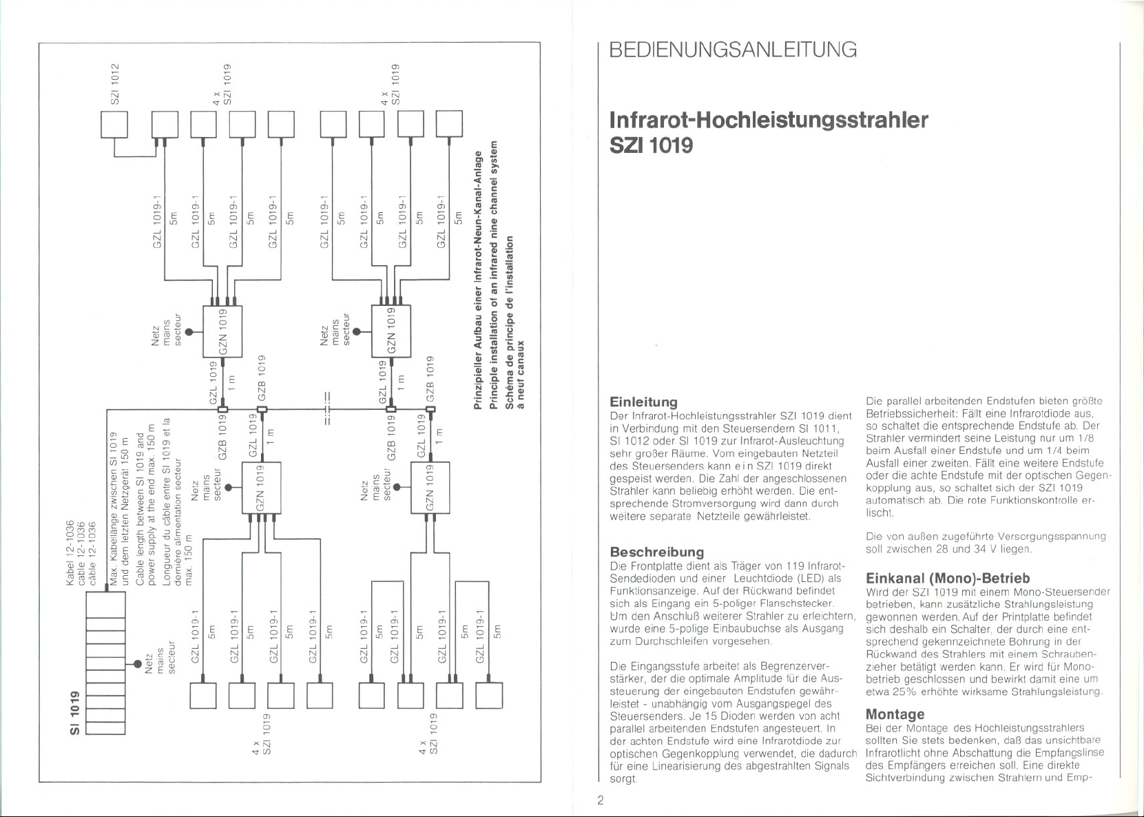
Der Infrarot-Hochleistungsstrahler SZI 1019 dient
in Verbindung mit den Steuersendern SI 1011,
SI 1012 oder SI 1019 zur Infrarot-Ausleuchtung
sehr großer Räume. Vom eingebauten Netzteil
des Steuersenders kann ein SZI 1019 direkt
gespeist werden, Die Zahl der angeschlossenen
Strahler kann beliebig erhöht werden. Die ent-
sprechende Stromversorgung wird dann durch
weitere separate Netzteile gewährleistet.
Beschreibung
Die Frontplatte dient als Träger von 119 Infrarot-
Sendedioden und einer Leuchtdiode (LED) als
Funktionsanzeige. Auf der Rückwand befindet
sich als Eingang ein 5-poliger Flanschstecker.
tJm den Anschluß weiterer Strahler zu erleichtern,
wurde eine 5-polige Einbaubuchse als Ausgang
zum Durchschleifen vorgesehen.
Die Eingangsstufe arbeitet als Begrenzerver-
stärker, der die optimale Amplitude für die Aus-
steuerung der eingebauten Endstufen gewähr-
leistet - unabhängig vom Ausgangspegel des
Steuersenders. Je 15 Dioden werden von acht
parallel arbeitenden Endstufen angesteuert, In
der achten Endstufe wird eine Infrarotdiode zur
optischen Gegenkopplung verwendet, die dadurch
für eine Linearisierung des abgestrahlten Signals
sorgt.
2
Die parallel arbeitenden Endstufen bieten größte
Betriebssicherheit: Fällt eine Infrarotdiode aus,
so schaltet die entsprechende Endstufe ab. Der
Strahler vermindert seine Leistung nur um 1/8
beim Ausfall einer Endstufe und um 1/4 beim
Ausfall einer zweiten. Fällt eine weitere Endstufe
oder die achte Endstufe mit der optischen Gegen-
kopplung aus, so schaltet sich der SZI 1019
automatisch ab. Die rote Funktionskontrolle er-
lischt.
Die von außen zugeführte Versorgungsspannung
soll zwischen 28 und 34 V liegen.
Einkanal (Mono)-Betrieb
Wird der SZI1019 mit einem Mono-Steuersender
betrieben, kann zusätzliche Strahlungsleistung
gewonnen werden. Auf der Printplatte befindet
sich deshalb ein Schalter, der durch eine ent-
sprechend gekennzeichnete Bohrung in der
Rückwand des Strahlers mit einem Schrauben-
zieher betätigt werden kann. Er wird für Mono-
betrieb geschlossen und bewirkt damit eine um
etwa 25% erhöhte wirksame Strahlungsleistung.
Montage
Bei der Montage des Hochleistungsstrahlers
sollten Sie stets bedenken, daß das unsichtbare
Infrarotlicht ohne Abschattung die Empfangslinse
des Empfängers erreichen soll. Eine direkte
Sichtverbindung zwischen Strahlern und Emp-
Page 3

Hochleistungsstrahler SZI1019
fängern sollte angestrebt werden, um bestmögliche
Empfangsverhältnisse zu schaffen. Eine recht
hohe Montage mit leichter Neigung nach unten
in den Raum hat sich in der Praxis als günstig
erwiesen
Flexibilität im Aufbau ist durch den 3/8"-Gewinde-
anschluß gegeben. Für den transportablen Einsatz
empfehlen wir die Tischklemmvorrichtung
MZT 237 oder das Stativ MZS 142, zwei Strahler
können mit Hilfe der Traverse MZS 235 montiert
werden. Für stationäre Installationen eignet sich
das Gelenk GZG 1019 (Wand- oder Decken-
befestigung).
Frequenzbereich
EIngangsimpedanz
Anzahl der Sendedioden
Mittlerer Strom durch eine Sendediode
Gesamte. mittlere Infrarot-Strahlungslelstung
Betnebsanzelge
Betnebsspannung
Stromaufnahme
HF-EIngangsspannung
Abmessungen mit Bügel In mm
Gewicht
Änderungen. vor allem zum technischen Fortschntt, vorbehalten
Die Verbindung der Hochleistungsstrahler mit
dem Sender erfolgt über eine flexible Steuerlei-
tung. Diese Steuerleitung überträgt die
HF-Signale zu den Hochleistungsstrahlern und
schaltet zugleich die angeschlossenen Netz-
geräte. Für feste Installationen kann das Spezial-
kabel als Meterware von uns bezogen werden.
Zur Ermittlung der erforderlichen Anzahl von
Hochleistungsstrahlern kann die folgende Faust-
formel herangezogen werden: Pro Kanal und 2 m2
Grundfläche eine Diode, das heißt, mit einem
Hochleistungsstrahler können bel Betrieb von vier
Kanälen rund 60 m2 ausgeleuchtet werden.
40 400 kHz
ca 5 k!!
119 Stück
ca. 100 mA
ca. 1.8 W
durch LED (rot)
28 34 V
ca. 1,1 A
0,8 Vss 5 V,
stets optimale ~
350 x 240 x 45
ca. 1,5 kg
durch Pegelautomatik
3
Page 4

USER'S GUIDE
Infrared High Power Radiator
SZI1019
\
.1
High power radiator SZI 1019
Introduction
The inlrared high power radiator SZI 1019 in
connection with inlrared transmitters SI 1011,
SI 1012 or SI 1019 serves to cover large areas.
The incorporated power supply 01 the inlrared
transmitter is able to leed 0 n e SZI 1019 directly.
The number 01 connected power radiators can be
increased without limit. The corresponding power
supply has to be provided by additional power
supply units.
Description
The lrant panel carries 119 inlrared transmitting
diodes and one LED as lunction contra!. On the
rear side you will lind the 5-pin input connector.
To lacilitate connection 01 additional power radia-
tors, a 5-pin output connector is provided for
interconnection.
The input stage works as limiter amplilier, giving
the guarantee 01 an optimal amplitude lor the
output stages - independent 01the output level
01 the inlrared transmitter. Eight parallel working
output stages are powering 15 diodes each.
Output stage no. 8 is equipped with one inlrared
diode with optical leedback, ensuring linearity of
the transmitted signal.
Parallel working output stages guarantee high
security: If one diode is defective the corresponding
4
output stage switches off. The radiated power
decreases by 1/8 with one output stage out of
order and by 1/4 with a second. II one more or
output stage no. 8 with optical leedback is out of
order, automatically the complete SZI 1019 and
the red LED lunction control switches off.
The external supply voltage must be between
28 and 34 V.
One channel (mono) operation
II the SZI 1019 is powered by a mono transmitter,
additional power can be obtained. Therelore you
will lind a switch mounted on the p. c. board,
wh ich may be selected by a screw-driver from
the rear side 01the radiator through an indicated
hole. By means 01 this switch mono operation
gives increased power 01 25%.
Positioning the IR-System
When positioning the high power radiator please
keep in mind that the invisible inlrared light must
reach the lens 01 the receiver without shadowing.
A visible connection between radiator and
receiver should be obtained to reach optimal
conditions. High positioning with a slight tilt down-
wards has been lound advantageous in practice.
Flexibility is given by means 01a 3/8" thread
adapter. For transportable use we recommend
the table clamp MZT 237 or the floor stand
MZS 142, two power radiators can be adapted
using the twin-bar MZS 235. For stationary in-
stallations swivel mount GZG 1019 (wall and
ceiling positioning) may be used.
The high power radiator is connected to the trans-
mitter by means 01 a Ilexible control cable.
This cable carries the RF-signal as
weil as the remote control signal to switch on the
Frequency range
Input impedance
Number 01transmlt1lngdiodes
.j
Average current 01one transmittlng diode
Totalaverage Inlrared transmifflng power
Funetlon control
Supply voltage
Current consumptlon
RF-Inpul voltage
Dimensions in mm wlth bracket
Weight
We reserve the fight to alter speelflcatlons. In partieular wlth regard to technlcallmprovements.
connected power supply units. For lixed installa-
tions this special cable (12 -1036) can be ordered
per meter.
The lollowing rule 01thumb serves lor determina-
tion 01the number 01 power radiators required:
Per channel and an area of 2 m2 one diode will be
required, that means wlth one high power radiator
and lour channels a coverage 01approximately
60 m2 can be obtained.
40 400 kHz
appx 5 k!J
119
appx. 100 mA
appx. 1.8 W
by LED (red)
28 .34 V
appx. 1.1 A
0.8 Vpp 5 automatlC gain
control optimum modulation
350 x 240 x 45
appx 1.5 kg
5
Page 5

MODE D'EMPLOI
Radiateur infrarouge a grande puissance
SZI1019
Introduction
Le radiateur infrarouge a gran,de puissance
SZI 1019 sert, en combinaison avec les emetteurs
pilote SI 1011, SI 1012 ou SI 1019, a I'eclairage
infrarouge de tres grandes salles, L'alimentation
incorporee de I'emetteur pilote permet d'alimenter
directement u n SZI 1019. Le nombre des radia-
teurs n'est pas limite. L'alimentation adequate
est alors garantie par des alimentations supple-
mentaires.
Description
La plaque frontale sert de support a 119 diodes
d'emission et a une diode luminescente (LED)
indicatrice. Le cote arriere comprend une fiche a
bride pentapolaire qui sert de fiche d'entree.
Afin de faciliter le raccord de radiateurs supple-
mentaires, une prise pentapolaire incorporee de
sortie a e18 prevue.
L'etage d'entree travaille comme amplificateur-
limiteur, qui garantit une amplitude optimale pour
la modulation des etages finaux, independamment
du niveau de sortie de I'emetteur pilote. Les huit
etages finaux travaillant en parallele attaquent
chacun 15 diodes. Dans le huitieme etage final,
une diode sert a la contre-reaction optique, afin
de proceder a une linearisation du signal emis.
Les huit etages de sortie travaillant en parallele
presentent une grande securite de fonctionne-
ment. Si une diode infrarouge est defaillante,
6
I'etage final concerne se met hors circuit. Le
radiateur ne diminue sa puissance que de 1/8
en cas de defaillance d'un etage de sortie et de
1/4 en cas de defaillance d'un deuxieme etage
final. Si un etage supplementaire est en defail-
lance, ou si le huitieme etage avec la contre-
reaction optique ne fonctionne plus, le SZI 1019
se met automatiquement hors circuit. La diode
rouge de controle s'eteint.
La tension d'alimentation externe doit se situer
entre 28 et 34 V.
Service clun canal (mono)
Si le SZI 1019 est relie a un emetteur pilote, il
est possible de gagner de puissance d'emission,
Pour cette raison, le circuit imprime est equipe
d'un commutateur qui est accessible par un
perc;:age marque, se trouvant sur la face arriere
du radiateur. La commutation se fait a I'aide d'un
tournevis. Pour le service mono, le commutateur
est ferme, entralnant par la suite une augmentation
de puissance de 25%.
Installation
En procedant a I'installation du radiateur de puis-
san ce, il faut toujours se rendre compte du fait
que la lumiere infrarouge invisible doit toujours
arriver a la lentille de reception sans voir d'objet
opaque sur son chemin. Une vue directe entre
Radiateur a grande puissance SZI1019
les radiateurs et les recepteurs est a conseiller
afin de creer les meilleures conditions de recep-
tion. En pratique, une installation relativement
elevee et legerement inclinee vers le bas de
I'espace s'est montree comme solution tres fa-
vorable a une bonne transmission.
La flexibilite pour I'installation est donnee par le
filetage 3/8". Pour un usage mobile, nous recom-
mandons la pince de fixation a serrage MZT 237
ou notre pied de micro MZS 142, deux radiateurs
pouvant iHre montes a I'aide de la reglette
MZS 235. Pour une installation stationnaire il ya a
disposition I'articulation GZG 1019 (fixation au
mur ou au plafond).
Bande passante
Impedance d'entree
Nombre de diodes d'emlSSlon
Courant moyen passant par une diode
Puissance Infrarouge moyenne totale
Indicateur de lonctlon
Tension d'alimentation
Courant de consommatlon
Tension d'entree HF
Dimensions en 10m (y compris bilde)
POlds
Modifications, surtoul dans I'interet du progres technique, reservees
La communication des radiateurs de puissance
a I'emetteur se fait a I'aide d'un cable pilote
flexible. Ce cable pilote transmet les
signaux HF vers les radiateurs de puissance et
effectue en meme temps la commutation des
alimentations raccordees. Pour des installations
fixes, ce cable special peut etre commande par
metres chez Senn heiser electronic..
Pour trouver le nombre requis de radiateurs a
grande puissance on peut utiliser la formule sui-
vante: Une diode par canal et pour une surface de
2 m2 c. a.d. un radiateur a grande puissance peut
eclairer une surface de 60 m2 en presence de
4 canaux.
40 400 kHz
env, 5 kfi
119
env, 100 mA
env, 1,8 W
LED (rouge)
28 34 V
env, 1,1 A
0,8 Vcc 5 Vcc, modulation toutours
optimale par commande de niveau automatique
350 x 240 x 45
env, 1,5 kg
7
Page 6

 Loading...