

Page 1
SZI 1015
IR Audio Transmission Technology | Modulators/Radiators
General Description
The SZI 1015 is a 2-Watt radiator with a coverage area of up to 400 m
is switched on and off automatically by the modulator’s RF carrier. The RF signal
from the modulator can be daisy- chained via BNC sockets. A barrier strip with RF
and DC inputs and outputs is connected in parallel. The radiator has a 5/8“ thread
and comes with a 3/8“ and 1/2“ adaptor, it can therefore easily be mounted to
various attachments.
2
. The radiator
Tec hni cal Da ta
IR diodes................................................................................72
Average radiating power ............................................... 2 W
Max. coverage area.................................................... 400 m
Carrier frequency range ............................30 kHz – 6 MHz
RF input ......................................50 mV – 3 V, approx. 5 kΩ
Inputs/outputs.......................... BNC sockets/barrier strip
Threshold voltage for
automatic on/off function ........................................50 mV
Operating voltage ............................................ 25 – 30 V DC
(via NT 1015 or SI 1015)
Current consumption
– operation........................................................ 0.7 A at 25 V
– stand-by .......................................................... max. 60 mA
Dimensions............................................ 250 x 100 x 80 mm
Weight ..............................................................approx. 1.3 kg
Cat. No. 004394
2
Features
j
2-Watt radiator for the carrier frequencies 2.3 and 2.8 MHz
j
Maximum coverage area of 400 m2, automatic
on/off function and RF output socket for daisy-chaining the signal to
additional radiators
j
Wide range of mounting accessories
j
Delivery includes: SZI 1015 radiator
Recommended Accessories
j
Mains unit
NT 1015-EU European version Cat. No. 004560
NZT 1015 -120USA version Cat. No. 004561
j
BNC-BNC co -axial cable
GZA 1019 A 1 (1 m) Cat. No. 002324
GZA 1019 A 5 (5 m) Cat. No. 002325
GZA 1019 A 10 (10 m) Cat. No. 002326
j
GZV 1019 A BNC coupler Cat. No. 002368
j
GZG 1029 swivel joint Cat. No. 003226
j
GZP 10 mounting plate Cat. No. 003139
j
MZT 100 anti-vibration table stand Cat. No. 001883
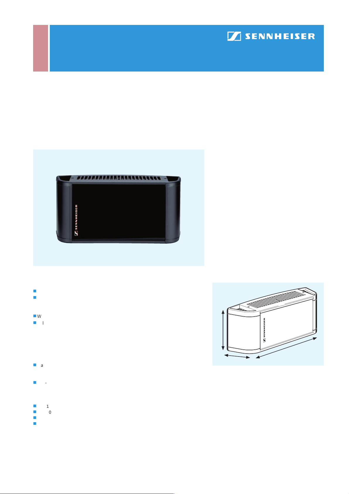
100 mm
250 mm
80 mm
Dimensions of the SZI 1015
Page 2
SZI 1015
IR Audio Transmission Technology | Modulators/Radiators
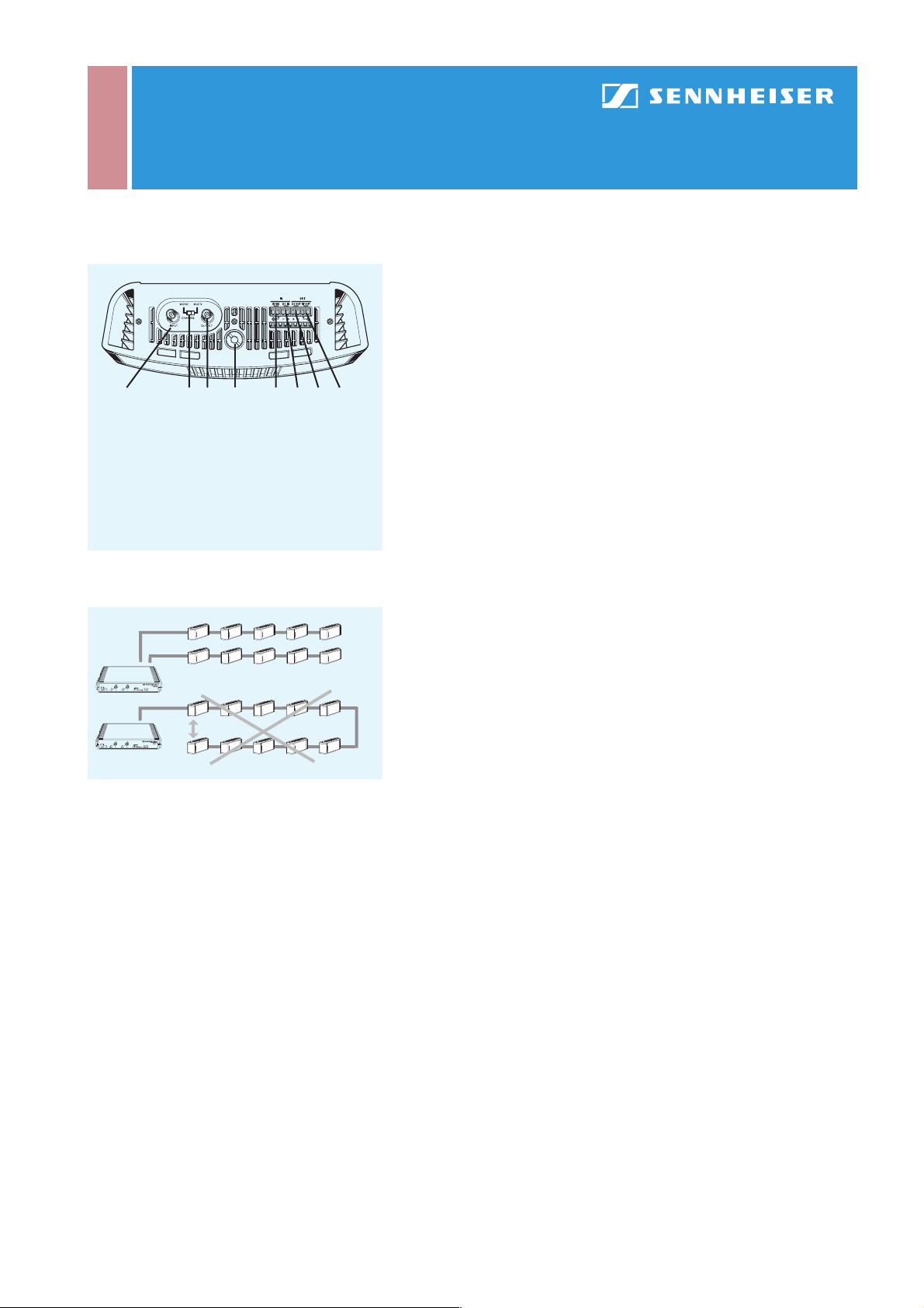
1 2 3 4 5 6 7 8
1 RF input (BNC)
2 Mono/multi switch
3 RF output (BNC)
4 Thread for mounting
5 RF input terminals
6 DC input terminals
7 DC output terminals
8 RF output terminals
Sockets and controls of the SZI 1015
50 Ω
50 Ω
With its compact size and various thread sizes (5/8“, 3/8“ and 1/2“), the SZI 1015
radiator makes for versatile mounting. It has a coverage area of up to 400 m
single-channel operation and can be switched between mono and multi-channel
operation. Please note that in multi-channel mode, this maximum coverage area
decreases proportionally with the number of channels transmitted.
The RF signal from the modulator is fed to the radiator via a BNC socket (1) and
can be daisy-chained to other radiators via the BNC RF output (3). Alternatively,
the modulator’s RF signal can also be fed to the barrier strip. Terminal 5 is the RF
input and terminal 8 the RF output for daisy-chaining the signal to further radiators. When using an SI 1015 modulator, the SZI 1015 does not need to be connected
directly to the mains via an NT 1015 mains unit, but can be supplied with the correct
DC voltage via the SI 1015 modulator.
The necessary supply voltage is also available at the barrier strip, terminal 6 being
the DC input and terminal 7 the DC output. For more information on how to connect
the signal and supply cables between the modulator and the radiator please refer
to the SI 1015 description. The SZI 1015 is fitted with an automatic on/off function:
when it receives a carrier from the modulator, it switches on – and off again when
the RF signal is no longer present. The switching threshold is 50 mV.
When setting up a radiator chain, you should bear in mind that the last radiator
in an RF chain must be fitted with a 50 Ω terminating impedance in order to avoid
standing waves. You should also keep in mind that signals can cancel out when
cables are very long and coverage areas of radiators overlap. In order to avoid reception problems, you should use both RF outputs of the modulator and set up two RF
chains (see also Planning Theory).
2
in
Creating RF chains
 Loading...