

Page 1
Page 2
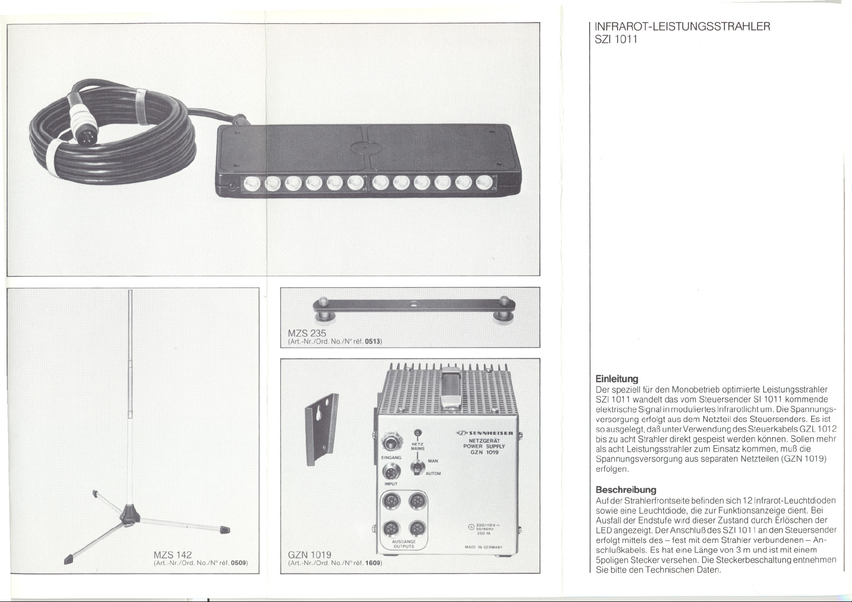
INFRAROT-LEISTUNGSSTRAHLER
SZI1 011
J
MZS235
(Art.-Nr./Ord. No./W
Einleitung
Der speziell für den Monobetrieb optimierte Leistungsstrahler
SZI1 011 wandelt das vom Steuersender SI1 011 kommende
elektrische Signal in moduliertes Infrarotlicht um. Die Spannungs-
. c'"
,
NETZ
MAINS
EINGANG A... MAN,
>Q:FSENNHlffIUn
NETZGERÄT
POW!:R SUPPlY
.GZN 10\9
.AUTOM,
>2M,O';"
~.
MZS 142
(Art,.Nr.lOrd. No.lW rel. 0509)
.
GZN1019
(Art.-Nr.lOrd.No./N' rel. 1609)
5MON'
25. VA
MAD(.. """AN'
versorgung erfolgt aus dem Netzteil des Steuersenders. Es ist
so ausgelegt, daßunter Verwendung des Steuerkabels GZL 1012
bis zu acht Strahler direkt gespeist werden können. Sollen mehr
als acht Leistungsstrahler zum Einsatz kommen, muß die
Spannungsversorgung aus separaten Netzteilen (GZN 1019)
erfolgen.
Beschreibung
Auf der Strahlerfrontseite befinden sich 12 Infrarot-Leuchtdioden
sowie eine Leuchtdiode, die zur Funktionsanzeige dient. Bei
Ausfall der Endstufe wird dieser Zustand durch Erlöschen der
LED angezeigt. Der Anschluß des SZI1 011 anden Steuersender
erfolgt mittels des - fest mit dem Strahler verbundenen - An-
schlußkabels. Es hat eine Länge von 3 m und ist mit einem
5poligen Stecker versehen. Die Steckerbeschaltung entnehmen
Sie bitte den Technischen Daten.
Page 3

Montage
Bei der Montage des Leistungsstrahlers sollten Sie stets be-
denken, daß das abgestrahlte Infrarotlicht die Empfängerlinse
des Empfängers auf direktem Wege, d. h. ohne Abschattung,
erreichen sollte. Deshalb ist die direkte Sichtverbindung
zwischen Strahlern und Empfängern als die beste Lösung an-
zusehen.
Um den jeweiligen Raum optimal auszuleuchten, sollten die
Strahler möglichst hoch und mit einer leichten Neigung nach
unten angebracht werden.
Als mechanische Anschlußmöglichkeit weist der SZI1 011 ein
3;g"-Gewinde auf, das dem Anwender viele Variationsmöglich-
keiten bei der Wahl der geeigneten Befestigungsvorrichtung
bietet. Für den transportablen Einsatz empfehlen wir die Tisch-
klemmvorrichtung MZT 237 oder das Stativ MZS 142. Mit Hilfe
der Traverse MZS 235 können zwei Strahler montiert werden.
Die elektrische Verbindung zwischen Steuersender und den
Strahlern wird über das Kabel GZL 1012 hergestellt. Di€ses
Kabel hat eine Länge von 38 m und ist mit vier 5poligen An-
schlußbuchsen ausgestattet. Zur Verkabelung von fest zu instal-
lien:!nden Anlagen empfehlen wir das Steuerkabel12-1 036, das
als Meterware von uns bezogen werden kann.
Projektierungshinweise
Zur Ermittlung der erforderlichen Anzahl von Leistungsstrahlern
gilt folgende Faustformel:
für 3 - 5 m2Grundflächeeine Diode,d. h.miteinem Leistungs-
strahler können max. 36 - 60 m2ausgeleuchtet werden.
EIngangspegel
Arbeitsfrequenz
Frequenzbereich
f.
I
I~
EingangsImpedanz
Wellenlangedes abgestrahlten Infrarotlichtes
Strahlungsleistung
Betriebsspannung
Stromaufnahme
BetrIebskontrolle
Gehauseabmessung
Langedes Anschlußkabels
Anschlußstecker
Gewicht
Anderungen, vor allem zum technischen Fortschritt, vorbehalten
300 1 000 mV
95 kHz
10kHz bis 180 kHz (- 3 dB)
ca. 25 kQ
950 nm
ca. 100 mW
27 bis 34 V
ca. 130 mA
durch Rotlichtdiode
200 x 80 x 23 mm
3m
Tuchel Nr. T 3360~002 oder ent~
sprechender Binderstecker
Nr. 09~0013~00~05
4 ~ HF, 2 ~ Schirm, 3 ~ -,5 ~ + UB
ca. 450 9
Page 4

INFRAREDPOWERRADIATOR
SZI1011
Installation
When installing the radiator, please keep in mind that the radiated
infrared light should reach the lens of the receiver without being
obstructed by obstacles. The best solution would be the visual
contact between radiator and receiver. To achieve an optimal
distribution of infrared light within the room, the radiator should be
installed as high as possible with a slight tilt downwards.
For mounting purposes the radiator is equipped with a3;g"-thread
to fit the table clamp MZT 237 or the floor stand MZS 142 for
portable use. The twin bar MZS 235 enables two SZI1 011 to be
mounted on it.
!
The connection between control transmitter and the radiators is
established with the contral cable GZL 1012. This cable is 38 m
long and is fitted with four 5-pin connection sockets. For
permanent installation the special contra I cable 12-1036 may be
ordered per meter from Senn heiser.
Hint for project planning
The following rule of thumb is valid to determine the number of
pO,werradiators required:
Foranareaof3- 5 m2one diodeis necessary,thatmeansone
powerradiatorcoversup to 36
- 60 m2.
Introduction
This infrared power radiator which has been optimized for mono-
aural operation with the control transmitter SI1 011 , converts the
electrical signal delivered by the control transmitter into
modulated infrared light. The supply voltage is derived from the
power supply of the transmitter. It is capable to feed up to 8
radiators which have to be connected via the cable GZL 1012.
Additional power supplies are necessary if more than 8 power
radiators are to be operated.
Description
The infrared light is emitted by the 12 infrared LEDs which are
fitted to the frant side of radiator. The red LED at the left side
serves as function contro!. In case the power stage of the radiator
becomes defective the LED will turn off.
For connection to the SI1 011 the radiator is equipped with a3 m
cable which is fitted with a 5-pin plug. For the wiring please refer
to the Technical Data.
Input level
Frequeney
Frequeney range
Input impedanee
Wavelength of radlated inlrared light
\
J
Radlated power
DC-supply voltage
Funetion mdleator
Dimensions
Length 01eonneelion eable
Conneetor
Connections
We reserve the rlght to alter speeifleatlons, 10partleular,
wlth regard to teehnieal improvements.
300-1000mV
95 kHz
10-180 kHz (- 3 dB)
appx. 25 kQ
950 nm
appx. 100 mW
27 - 34 V
by LED, red
200 x 80 x 23 10m
3m
Tuchei, No. T 3360-002 or Binder,
No. 09-0013-00-05
Pin4 ~ RF
Pm2 ~ sereen
Pm3 ~ - supply voltage
Pm5 ~ +supply voltage
appx. 450 g
Page 5

RAOIATEUROEPUISSANCE INFRAROUGE
SZI1011
Montage
Lors du montage du radiateur de puissance, il faut veiller ace que
la lumiere infrarouge emise vienne tout droit sur lalentille de
reception, c. a. d. sans trouver d'objet opaque sur son chemin, la
meilleure solution etant la liaison optique directe entre les
radiateurs et les recepteurs.
Pourtrouver laposition optimale des radiateurs, il est conseille de
les placer le plus haut possible, legerement inclines vers le bas.
Le raccordement mecanique est fait par I'intermediaire d'un
taraudage 3;g" qui offre une multitude de possibilites pour le
choix du dispositif de fixation approprie. Pour un service mobile,
nous vous conseillons la pince de fixation a serrage MZT 237 ou
le pied MZS 142. La reglette MZS 235 permet de fixer deux
radiateurs.
Le raccordement electrique entre I'emetteur pilote et les radia-
teurs est assure par le cable GZL 1012. 11aune longueur de 38 m
et est equipe de quatre fiches pentapolaires. Pour effectuer le
branchement d'installations fixes, nous tenons adisposition le
cable pilote 12-1036 (livraison par metre courant).
Indications de projet
Pour trouver le nombre requis de radiateurs de puissance
procedez selon la formule suivante:
Une diode pour une surface de 3- 5 m2,c. a. d. un radiateur de
puissancepourelairerune surfacemax.de 36- 60 m2 c.
Introduction
Le radiateur de puissance infrarouge SZI1 011 est un radiateur
optimise pour la transmission mono infrarouge. 11transforme le
signal electrique, qui vient de I'emetteur SI1 011, en lumiere infra-
rouge modulee. L'alimentation est assuree par I'alimentation de
I'emetteur pilote: Elle est capable d'alimenter jusqu'a 8 radiateurs
sion utilise le cable pilote GZL 1012. Si le nombre de huit radiateurs
est depasse, I'alimentation doit etre assuree pardes alimentations
secteur apart (GZN 1019).
Description
Le cote avant du radiateur heberge 12 diodes luminescentres
infrarouges ainsi qu'une diode d'indication. Si I'etage final est
defaillant, la diode LED s'eteint. Le raccordement du SZI1 011 a
I'emetteur pilote se fait par I'intermedialaire du cable de raccorde-
ment, fixe au radiateur. Sa longueur est de 3 m, il est equipe d'une
fiche pentapolaire. Pour le branchement des broches, voir
caracteristiques techniques.
Niveaud'entree
Frequenee . . .
Gammedesfrequenees
f,
$
Impedaneed'entree ... .. .
Longueurd'onde de lalumiereInfrarouge
PUlssaneerayonnee
Tensiond'ahmentatlon
Consommationde eourant
Contraledesfonetions
DimensionsduboitIer .
Langueurdu cablede raeeordement
Conneeteurs
POlds
Modlfieatlons, surtout dans I'lnteret du progres teehnique, reservees.
300 1000 mV
95 kHz
10kHz 180kHz
env. 25 kQ
950 nm
env. 100 mW
27 a 34 V
env. 130 mA
diode rouge
200 x 80 x 23 mm
3m
Tuchel No.T3360-002 ou flehe
Binder No. 09-0013-00-05
4~ HF, 2 ~ bllndage, 3 ~ -, 5 ~ UB
env. 450 9
Page 6

 Loading...