

Page 1
Using the transmitter
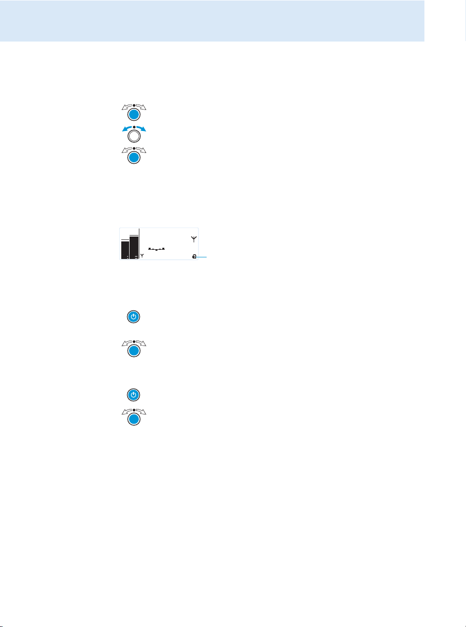
Deactivating the lock mode temporarily
You can activate or deactivate the automatic lock mode via the “Auto Lock” menu item. If the
lock mode is activated, you have to temporarily deactivate it In order to be able to operate
the transmitter:
왘 Press the jog dial.
“Locked” appears on the display panel.
왘 Turn the jo g dial .
“Unlock?” appears on the display panel.
왘 Press the jog dial.
The lock mode is temporarily deactivated.
– When you are in the operating menu, the lock mode remains deactivated until
you exit the operating menu.
– When the standard display is shown, the lock mode is automatically activated
after 10 seconds.
The lock mode icon & flashes prior to the lock mode being activated again.
PEAK
PEAK
B.Ch: 5.14
0
0
-10
-10
-20
-20
-30
-30
EQ
-40
-40
Standard -18dB
AF I
AF II
552.300
**2000**
MHz
&
Activating/deactivating the RF signal
To deactivate the RF signal:
왘 When the standard display is shown on the display panel, press the STANDBY
button.
“RF Mute On?” appears on the display panel.
왘 Press the jog dial.
The RF signal is deactivated. “RF Mute” flashes in alternation with the standard
display and the display is backlight in red.
To activate the RF signal:
왘 Press the STANDBY button.
“RF Mute Off?” appears on the display panel.
왘 Press the jog dial.
The RF signal is activated and the display backlighting changes from red to
orange.
To deactivate the RF signal on switch-on:
왘 See “offline operation” on page 13.
14
Adjusting the audio channels
Via the “Mode” menu item, you can adjust the audio channels.
왘 Select “Stereo” if you want to transmit two separate audio signals on channel I and
channel II (e.g. channel I = audio signal of the presenter/musician, channel II = sum of all
audio signals).
This allows the presenter/musician to adjust the balance between the left and right stereo
signal on his receiver.
왘 Select “Mono” if you only want to transmit an audio signal on one channel. In this case,
the signal from the left audio input
BAL AF IN L (I)
is transmitted.
Page 2
During mono operation, you have to deactivate the pilot tone evaluation on the
Stereo Transmitter SR 2000 IEM
PEAK
-10
0
-20
-30
-40
PEAK
-10
0
-20
-30
-40
AF I
AF II
EK 2000 IEM receiver in order to ensure that your receiver outputs the same signal
on channel I and II.
Monitoring the audio signal via headphones
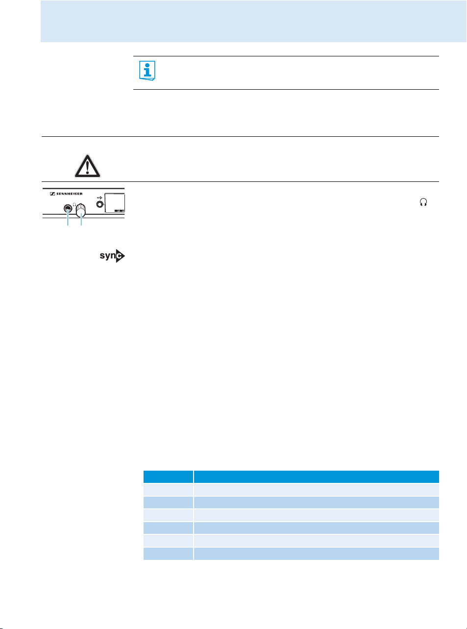
You can monitor the audio signal via the headphone output .
CAUTION! Danger of hearing damage!
Listening at high volume levels for long periods can lead to permanent hearing defects.
왘 Set the headphone volume control to the minimum position before putting the head-
phones on.
왘 Set the headphone volume control to the minimum position.
왘 Connect headphones with a ¼” (6.3 mm) stereo jack plug to the headphone output .
왘 Gradually increase the volume and monitor the audio signal with the lowest possible
volume.
Synchronizing transmitters and EK 2000 IEM receivers via the
infra-red interface
Synchronization allows you to quickly and easily transfer transmitter and receiver settings
from one device to the other, especially if you want to configure a multi-channel system.
There are two transfer directions:
1. Easy Setup Sync: Transfer from the receiver to one or several transmitters
Once you have performed a frequency preset scan with your receiver, you can use the
Easy Setup Sync function to transfer unused frequency presets from the receiver to the
transmitters via the infra-red interface. In order to configure a multi-channel system, you
use the diversity receiver to transfer the first unused channel from the selected frequency
bank to the first transmitter and the next unused channel to the second transmitter and
so on, thus ensuring that all transmitters of a multi-channel system operate on suitable
frequencies.
2. Sync: Transfer from a transmitter to a receiver
Once you have selected and set the desired receiver settings on the transmitter (either
manually or using the Easy Setup Sync function), you transfer these settings to a receiver.
This configures the receiver and establishes a transmission link between transmitter and
receiver.
Via the “Sync Settings” submenu, you can adjust the receiver parameters listed below and
activate or deactivate their transfer to an EK 2000 IEM receiver.
Setting Transferred receiver parameter
“Balance” Current balance setting (“−15”/“+15”)
“Squelch” Current squelch setting (“Off”, “5 dB” ... “25 dB”)
“Mode” Current audio mode setting (“Stereo”/“Focus”)
“High Boost” Current treble boost setting (“flat”/“High boost”)
“Auto Lock” Current lock mode setting (“active”/“inactive”)
“Limiter” Current limiter setting (“−18 dB”, “−12 dB”, “−6dB”, “Off”)
Using the transmitter
15
Page 3
Using the transmitter
OFF
2
4
6
PHONES
OFF
2
4
6
PHONES
When carrying out the Sync function, the transmitter’s current frequency bank and
channel setting as well as the receiver parameters adjusted via the “Sync Settings”
submenu are transferred to the EK 2000 IEM receiver via the infra-red interface.
Carrying out an Easy Setup Sync or a Sync function
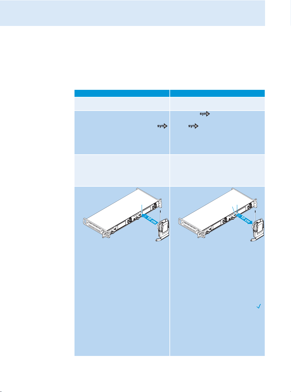
The following assumes that you are using the Easy Setup Sync function for setting up a multichannel system. You can also you the Easy Setup Sync function for establishing a transmis-
sion link between one transmitter and one
EK 2000 IEM
Easy Setup Sync Sync
왘 Switch all transmitters and one diversity
receiver on.
왘 On all transmitters, call up the “Easy
Setup” menu item.
The text “Easy Setup Sync” and the
icon appear on the display panels of the
transmitters.
The RF signal of the transmitters is automatically deactivated.
왘 Use your diversity receiver to perform a
frequency preset scan and select a
channel within a frequency bank with a
sufficient number of unused channels (see
the instruction manual of the receiver).
receiver.
왘 Switch your transmitter and your
diversity receiver on.
왘 Press the button on the trans-
mitter.
The icon appears on the display
panels of the transmitter.
–
16
왘 Place the infra-red interface of the
receiver (see the instruction manual of
the receiver) in front of the infra-red
interface of the first transmitter.
The next unused frequency preset is
transferred from the receiver to the
transmitter.
As soon as the transfer is completed, the
display panel of the transmitter displays
the numbers of the transferred frequency bank and channel.
Please note that the transmitter does not
automatically store the frequency bank
and channel setting.
왘 Place the infra-red interface of the
receiver (see the instruction manual of
the receiver) in front of the infra-red
interface of your transmitter.
The parameters adjusted via the “Sync
Settings” menu item are transferred
from the transmitter to the receiver
In addition, the current frequency bank
and channel setting is transferred.
When the transfer is completed, “ ”
appears on the display panel of the transmitter. The transmitter then switches
back to the standard display.
The transferred parameters are automatically adjusted and stored by the receiver.
The transmission link between transmitter and receiver is now established.
.
Page 4
Easy Setup Sync Sync
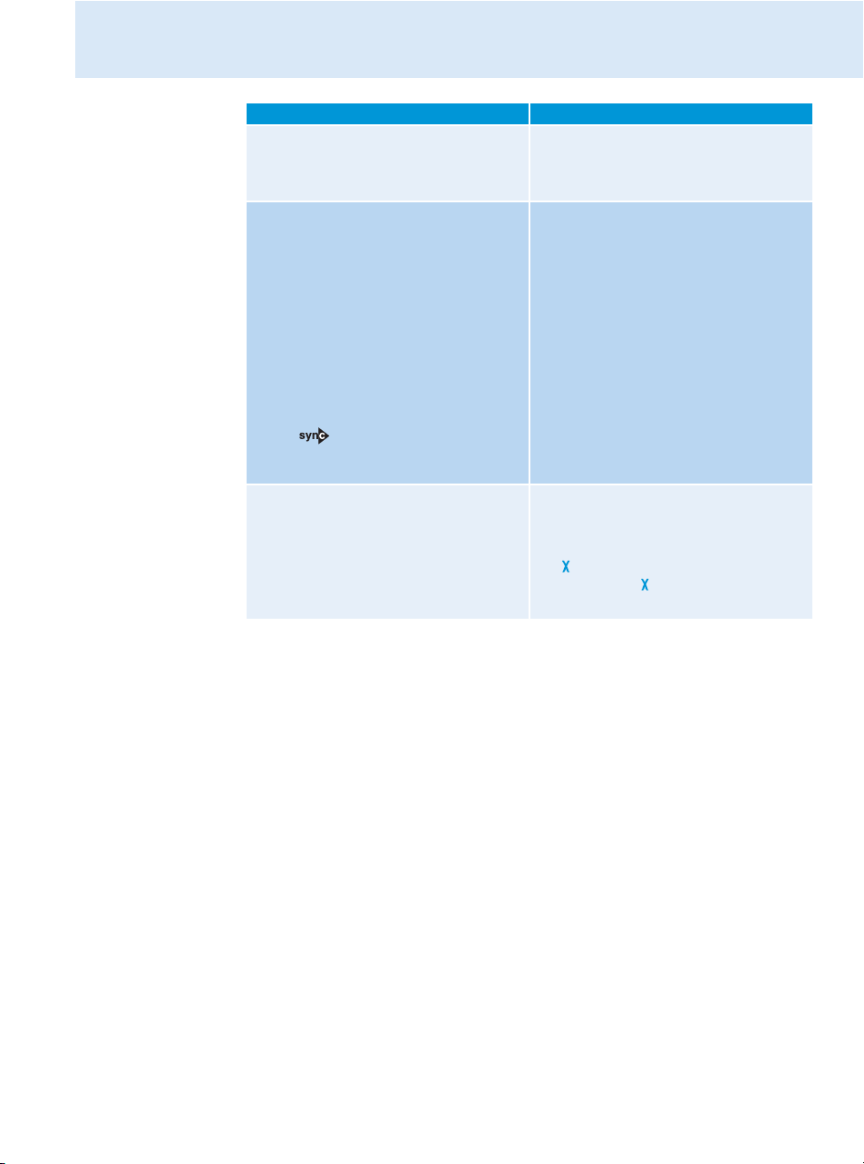
왘 Place the infra-red interface of the diver-
sity receiver in front of the infra-red
interfaces of the remaining transmitters,
one after the other.
왘 Store the frequency bank and channel
setting by pressing the jog dial on your
transmitters. You can carry out the Sync
function (see right-hand column) at a
later time to establish a transmission link
between transmitters and receivers.
OR:
왘 Immediately synchronize your receivers
with your transmitters by carrying out the
Sync function (see right-hand column).
This establishes a transmission link
between transmitters and receivers.
The icon in the left lower corner of
the transmitter display indicates that the
Sync function can be carried out.
–
To cancel the transfer:
왘 Press the STANDBY button on the trans-
Using the transmitter
–
–
mitter.
“ ” appears on the display panel of the
transmitter. “ ” also appears if no suitable receiver was found.
17
Page 5
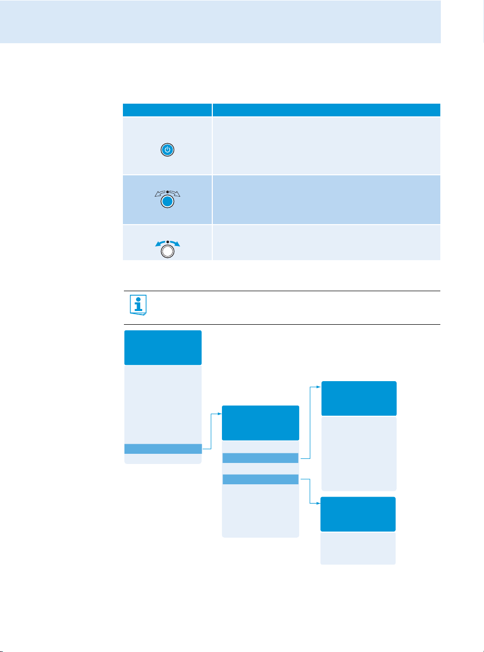
Using the operating menu
Sensitivity
Easy Setup
Mode
Frequency Preset
Name
Equalizer
AutoLock
Advanced
Exit
Main menu
“Menu”
Tune
Sync Settings
RF Power
Warnings
LCD Contrast
Reset
IP-Address
Software Revision
Exit
Extended menu
“Advanced Menu”
AF Peak
RF Mute
Exit
“Warnings”
Balance
Squelch
Mode
High Boost
Auto Lock
Limiter
Exit
“Sync Settings”
Using the operating menu
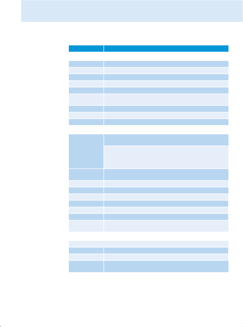
The buttons
Button Function of the button
Press the STANDBY
button
Press the jog dial • Changes from the standard display to the operating menu
Turn the jog dial • Changes to the next/previous menu item
Overview of the operating menu
For more detailed information on the operating menu, refer to the instruction
manual of the SR 2000 IEM/SR 2050 IEM which can be downloaded from the
SR 2000 IEM/SR 2050 IEM product page at www.sennheiser.com.
• Switches the transmitter on and off
• Cancels the entry and returns to the standard display
(ESC function)
• Activates/deactivates the RF signal
(special function, see page 14)
• Calls up a menu item
• Enters a submenu
• Stores the settings and returns to the operating menu
• Changes the setting of a menu item
18
Page 6
Using the operating menu
When the standard display is shown on the display panel, you can get into the main menu by
pressing the jog dial. The extended menu “Advanced Menu” and the other menus can be
accessed via the corresponding menu items.
Display Function of the menu item
Main menu “Menu”
Sensitivity Adjusts the input sensitivity
Easy Setup Deactivates the RF signal and activates Easy Setup Sync (see page 15)
Mode Selects mono or stereo operation
Frequency Preset Changes the frequency bank and the channel
Name Enters the transmitter name
Equalizer Changes the frequency response of the output signal using a graphic
equalizer
AutoLock Activates/deactivates the automatic lock mode
Advanced Calls up the extended menu “Advanced Menu”
Exit Exits the operating menu and returns to the standard display
Extended menu “Advanced Menu”
Tune Sets the transmission frequencies for the frequency banks “U1” to
“U6”
Special function: Sets a channel and a transmission frequency for the
frequency banks “U1” to “U6”:
왘 Select this menu item and call it up by pressing the jog dial until
the channel selection appears.
Sync Settings Adjusts the receiver parameters to be transferred to the receiver and
activates/deactivates the transfer (see table on page 15)
RF Power Adjusts the transmission power
Warnings Calls up the submenu “Warnings”
LCD Contrast Adjusts the contrast of the display panel
Reset Resets the transmitter
IP-Address Adjusts the IP address of the transmitter
Software Revision Displays the current software revision
Exit Exits the extended menu “Advanced Menu” and returns to the main
menu
Submenu “Warnings”
Activates/deactivates warnings (color change and warning messages):
AF Peak Audio overmodulation
RF Mute RF signal is deactivated
Exit Exits the submenu “Warnings” and returns to the extended menu
“Advanced Menu”
19
Page 7
Using the operating menu
Squelch
Easy Setup
Frequency Preset
Name
AF Out
Equalizer
Auto Lock
Advanced
Exit
Menu
Working with the operating menu
If the lock mode is activated, you have to deactivate it In order to be able to work
with the operating menu (see page 14).
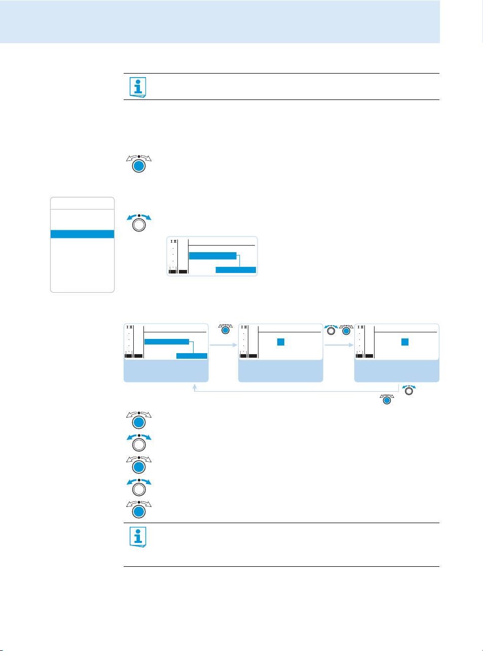
By way of example of the “Frequency Preset” menu, this section describes how to use the
operating menu.
Changing from the standard display to the operating menu
왘 Press the jog dial.
The standard display is replaced by the main menu. The last selected menu item
is displayed.
Selecting a menu item
왘 Turn the jog dial to change to the “Frequency Preset” menu item.
The current setting of the selected menu item is displayed:
PEAK
Menu
040
Easy Setup
-10
30
-20
Frequency Preset
20
-30
Name
10
-40
AF
RF
Changing and storing settings
PEAK
Menu
040
-10
Easy Setup
30
-20
Frequency Preset
20
-30
10
Name
-40
AF
RF
Call up “Frequency
Preset”
B.Ch: 5.14
B. Ch: 1. 1
PEAK
-10
30
-20
20
-30
10
-40
AF
RF
Select the frequency
bank and confirm
Frequency Preset
040
B.Ch: 5.14
543.000 MHz
PEAK
Frequency Preset
040
-10
30
-20
B.Ch: 5.14
20
-30
10
-40
AF
RF
543.000 MHz
Select the channel;
store the setting
20
“Stored”
왘 Press the jog dial to call up the menu item.
왘 Turn the jog dial to set the frequency bank.
왘 Press the jog dial to confirm your selection.
왘 Turn the jog dial to set the channel.
왘 Press the jog dial to store the setting.
By briefly turning the jog dial to the left or right, the display jumps either forwards
or backwards to the next menu item or setting. If you turn the jog dial to the left or
right and hold it in this position, the display cycles continuously (“fast search”
function).
Page 8
Canceling an entry
Squelch
Easy Setup
Frequency Preset
Name
AF Out
Equalizer
Auto Lock
Advanced
Exit
Menu
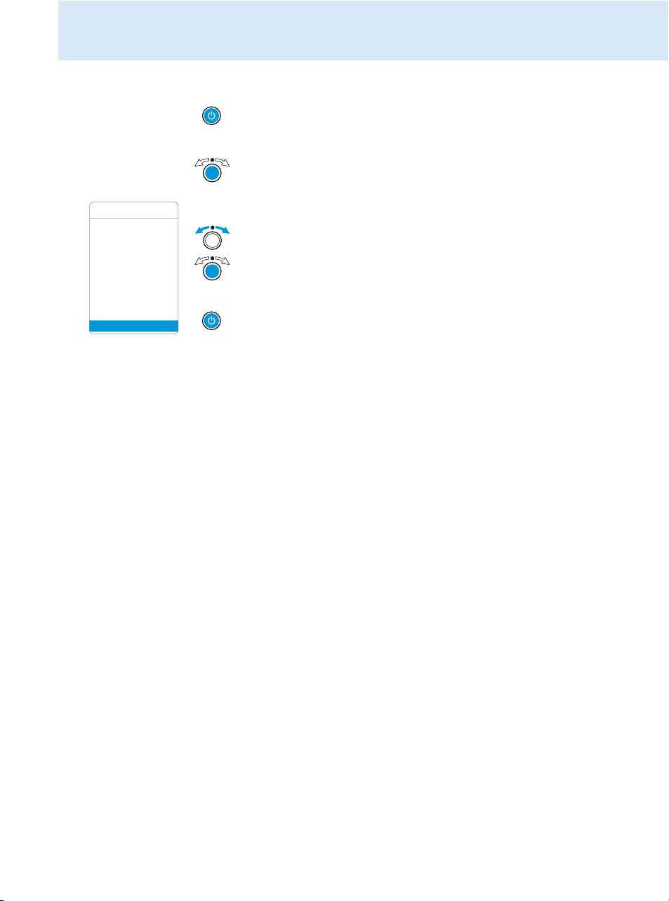
왘 Press the STANDBY button to cancel the entry.
The standard display appears on the display panel.
To return to the last edited menu item:
왘 Press the jog dial repeatedly until the last edited menu item appears.
Exiting a menu item
왘 Change to the “Exit” menu item.
왘 Confirm your selection.
You return to the next higher menu level.
To directly return to the standard display:
왘 Press the STANDBY button.
Using the operating menu
21
Page 9
Synchronizing the transmitter with an EK 2000 IEM receiver
Stereo Transmitter SR 2050 IEM
Stereo Transmitter SR 2050 IEM
Stereo Transmitter SR 2050 IEM
Synchronizing the transmitter with an EK 2000 IEM
receiver
When synchronizing your transmitter with an EK 2000 IEM receiver, please observe the
following:
왘 Only use a transmitter and a receiver from the same frequency range (see the
type plate on the transmitter and the receiver).
왘 Make sure that the desired frequencies are listed in the enclosed frequency infor-
mation sheet.
왘 Make sure that the desired frequencies are approved and legal in your country
and, if necessary, apply for an operating license.
Synchronizing the transmitter with an EK 2000 IEM receiver – individual operation
Upon delivery, transmitter and receiver are synchronized with each other. If, however, you
cannot establish a transmission link between transmitter and receiver, you have to synchronize the channels of the devices:
왘 Carry out the Easy Setup Sync function and then the Sync function (see
Alternatively, you can set the channel on the transmitter manually:
왘 Make sure that you set the transmitter to the same frequency bank and the same channel
as the receiver.
Synchronizing transmitters with EK 2000 IEM receivers – multi-channel operation
Network operation
using the WSM
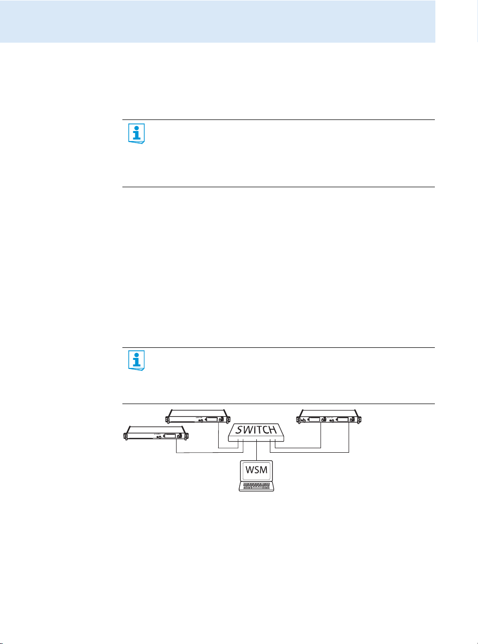
In multi-channel operation, the transmitters are remote controlled via a PC running the
“Wireless Systems Manager” (WSM) software.
Advantages of controlling the transmitters via the “Wireless Systems Manager”
(WSM) software:
• Detailed overview of all transmission and receiving channels
• Remote control of all transmitters in the network
• Combination of transmitters of different frequency ranges (see page 4).
page 16)
.
Operation without
22
network
왘 Connect your transmitters and your PC in a network (see page 12).
왘 Switch your transmitters and your PC on.
왘 Launch the “Wireless Systems Manager” (WSM) software.
왘 To set up your multi-channel system, proceed as described in the instruction manual of
the “Wireless Systems Manager” (WSM) software.
왘 Carry out the Easy Setup Sync function and then, for each transmission link, the Sync
function (see
page 16).
Page 10
Using freely selectable transmission frequencies
You can also freely select the frequencies and store these frequencies in the frequency banks
“U1” to “U6”.
If you want to use the frequency banks “U1” to “U6”:
왘 Make sure to use transmitters and receivers from the same frequency range (see page 4
and the type plates of the devices).
To ensure that the desired frequencies are intermodulation-free:
왘 Contact your Sennheiser partner (see www.sennheiser.com).
왘 Set each transmitter to the same frequency bank.
왘 On one of the transmitters, select a channel within this frequency bank (see page 19).
왘 Assign this channel one of the calculated transmission frequencies (see page 19).
왘 Synchronize a receiver with your transmitter ( , see
OR
왘 Manually set the receiver to the same frequency bank, channel and frequency that you set
on the transmitter.
왘 Repeat for the remaining transmitters and receivers as described above.
Cleaning the transmitter
CAUTION! Liquids can damage the electronics of the transmitter!
Liquids entering the housing of the device can cause a short-circuit and damage the
electronics.
왘 Keep all liquids away from the transmitter.
왘 Before cleaning, disconnect the device from the mains.
왘 Use a slightly damp cloth to clean the device from time to time. Do not use any solvents
or cleansing agents.
Cleaning the transmitter
page 16
)
Accessories
Cat. No.
004368 GA 3030 AM antenna front mount kit
502048 AC 3200 antenna combiner
500887 A 5000 CP circularly polarized broadband antenna
003658 A 2003 directional broadband antenna
004645 A 1031 omni-directional broadband antenna
087969 Antenna daisy-chain cable, 50 Ω, BNC, 0.25 m
002324 GZL 1019-A1 coaxial cable, type RG 58, BNC to BNC, 1 m
Accessory
23
Page 11
If a problem occurs ...
24
If a problem occurs ...
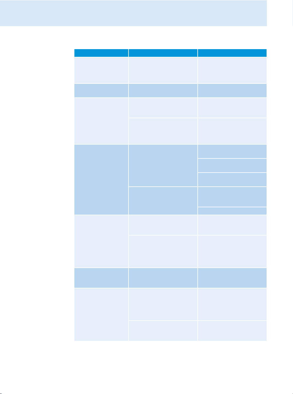
Problem Possible cause Possible solution
Transmitter cannot be
operated, “Locked”
appears on the display
panel
No operation indication No mains connection Check the connections of the
No RF signal at the
receiver
Very weak RF signal at
the receiver
RF signal available,
no audio signal at the
receiver
Audio signal has a high
level of background
noise
Audio signal is distorted If “AF PEAK” additionally
If a problem occurs that is not listed in the above table or if the problem cannot be solved with
the proposed solutions, please contact your local Sennheiser partner for assistance.
To find a Sennheiser partner in your country, search at www.sennheiser.com under “Service
& Support”.
Lock mode is activated Deactivate the lock mode
Transmitter and receiver are
not on the same channel
If “RF Mute” additionally
appears on the transmitter
display:
RF signal is deactivated
Transmission range is
exceeded
Receiver’s squelch threshold is
adjusted too high
No input signal at the
transmitter
Very low input signal Check the audio level on the
Transmitter sensitivity is
adjusted too low
appears on the transmitter
display:
transmitter sensitivity is
adjusted too high
Receiver’s audio output level
is adjusted too high
(see page 14 and page 18).
mains cable (see page 12).
Synchronize the transmitter
with the receiver (see
page 15).
Activate the RF signal
(see page 14).
Check the squelch threshold
setting on the receiver.
Reduce the distance between
receiver and transmitter.
Increase the transmission
power (see page 19).
Reduce the squelch threshold
(see the instruction manual of
the receiver).
Reposition the antennas.
Check the audio level on
the transmitter display
(see page 7).
transmitter display (see
page 7), increase the level of
the input signal or adjust the
input sensitivity (see page 19).
Adjust the transmitter sensitivity correctly (see page 19).
Adjust the transmitter
sensitivity correctly.
Reduce the audio output level
(see the instruction manual of
the receiver).
Page 12

Specifications
Specifications
RF characteristics
Frequency ranges 516–558, 558–626, 626–698, 718–790, 790–865 MHz
(Aw to Dw, Gw, see page 4)
Transmission frequencies up to 3,000 frequencies, tuneable in steps of 25 kHz
20 frequency banks, each with up to 32 factory-preset channels
6 frequency banks, each with up to 32 user programmable
channels
Switching bandwidth up to 75 MHz
Frequency stability ±10 ppm (–10°C to +55°C)
Antenna output BNC socket, 50 Ω
RF output power at 50 Ω typ. 10/30/50 mW (Low/Standard/High), switchable
AF characteristics
Modulation wideband FM stereo (MPX pilot tone)
Compander system Sennheiser HDX
Nominal/peak deviation ±24 kHz/±48 kHz
MPX pilot tone (frequency/deviation) 19 kHz/±5 kHz
AF frequency response 25 Hz to 15 kHz
AF input
Max. input level +22 dBu
THD
(at 1 kHz and nominal deviation) < 0.9%
Signal-to-noise ratio at nominal load
and peak deviation > 90 dB
AF output LOOP OUT BAL L (I)/LOOP OUT BAL R (II) ¼’’ (6.3 mm) stereo jack socket, balanced
BAL AF IN L (I)/BAL AF IN R (II)
2 x
XLR-3/
¼’’ (6.3 mm) jack combo socket,
electronically balanced
Overall device
Temperature range –10°C to + 55°C
Power supply 100–240 V~
Current consumption SR 2000: 0.1 A
Dimensions approx. 217 x 483 x 43 mm
Weight
SR 2050: 0.2 A
SR 2000: approx. 2500 g
SR 2050: approx. 2700 g
In compliance with
Europe
EMC EN 301489-1/-9
Radio EN 300422-1/-2, EN 300454-1/-2
Safety EN 60065
25
Page 13
Manufacturer Declarations
Approved by
Canada Industry Canada RSS 123
and 2099A-SR2050
IC: 2099A-SR200
li
mited to 806 MHz
USA FCC-Part 74
li
mited to 698 MHz
0
FCC-ID: DMOSR200
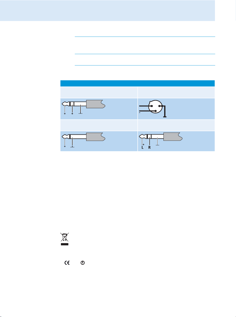
Connector assignment
Audio
¼’’ (6.3 mm) stereo jack plug,
balanced (Audio In/Loop out)
and DMOSR2050
0
XLR-3F connector,
balanced (Audio In)
+
21
3
¼’’ (6.3 mm) mono jack plug,
unbalanced (Audio In/Loop out)
¼’’ (6.3 mm) stereo jack plug
for headphone output
Manufacturer Declarations
Warranty
Sennheiser electronic GmbH & Co. KG gives a warranty of 24 months on this product.
For the current warranty conditions, please visit our web site at www.sennheiser.com or
contact your Sennheiser partner.
In compliance with the following requirements
• RoHS Directive (2002/95/EC)
• WEEE Directive (2002/96/EC)
Please dispose of the transmitter at the end of its operational lifetime by taking it to
your local collection point or recycling center for such equipment.
CE Declaration of Conformity
•
0682
• R&TTE Directive (1999/5/EC), Low Voltage Directive (2006/95/EC)
The declarations are available at www.sennheiser.com.
Before putting the device into operation, please observe the respective country-specific
regulations.
26
Page 14

Manufacturer Declarations
Statements regarding FCC and Industry Canada
This device complies with Part 15 of the FCC Rules and with RSS-210 of Industry Canada.
Operation is subject to the following two conditions: (1) this device may not cause harmful
interference, and (2) this device must accept any interference received, including interference that may cause undesired operation.
This equipment has been tested and found to comply with the limits for a Class B digital
device, pursuant to Part 15 of the FCC Rules. These limits are designed to provide reasonable
protection against harmful interference in a residential installation. This equipment generates, uses and can radiate radio frequency energy and, if not installed and used in accordance
with the instructions, may cause harmful interference to radio communications. However,
there is no guarantee that interference will not occur in a particular installation. If this equipment does cause harmful interference to radio or television reception, which can be determined by turning the equipment off and on, the user is encouraged to try to correct the interference by one or more of the following measures:
• Reorient or relocate the receiving antenna.
• Increase the separation between the equipment and receiver.
• Connect the equipment into an outlet on a circuit different from that to which the receiver
is connected.
• Consult the dealer or an experienced radio/TV technician for help.
This class B digital device complies with the Canadian ICES-003.
Changes or modifications made to this equipment not expressly approved by Sennheiser
electronic Corp. may void the FCC authorization to operate this equipment.
Before putting the device into operation, please observe the respective country-specific
regulations!
27
Page 15

Sennheiser electronic GmbH & Co. KG
Am Labor 1, 30900 Wedemark, Germany
www.sennheiser.com
Printed in Germany
Publ. 01/09
529682/A01
 Loading...