

Page 1
GEBRAUCHSANLEITUNG
INSTRUCTIONS FOR USE
INSTRUCTIONS POUR L‘USAGE
ISTRUZIONI PER L‘USO
MODO DE EMPLEO
GEBRUIKSAANWIJZING
BRUKSANVISNING
SYSTEM 2013 PLL
Page 2
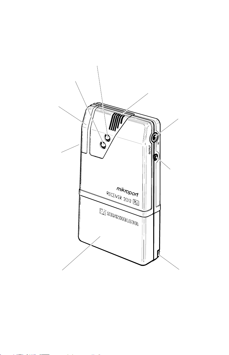
EK 2013 PLL
1
RECEPTION AND
BATTERY INDICATOR LAMP
LOCKABLE
COVER
CHANNEL
SELECTOR SWITCH
FOR UP TO 16
FREELY-SELECTABLE
FREQUENCIES
TRANSMISSION
INDICATOR LAMP
BUILT-IN
MICROPHONE
OUTPUT JACK
FOR CONNECTION
TO HEARING AID
HEADPHONE
OUTPUT JACK
INTERCHANGEABLE
STANDARD OR
RECHARGEABLE
BATTERY PACK
2.1
CHARGING CONTACT FOR CHARGING
IN CHARGING UNIT L 2013 (ONLY ON
RECHARGEABLE BATTERY PACK)
Page 3
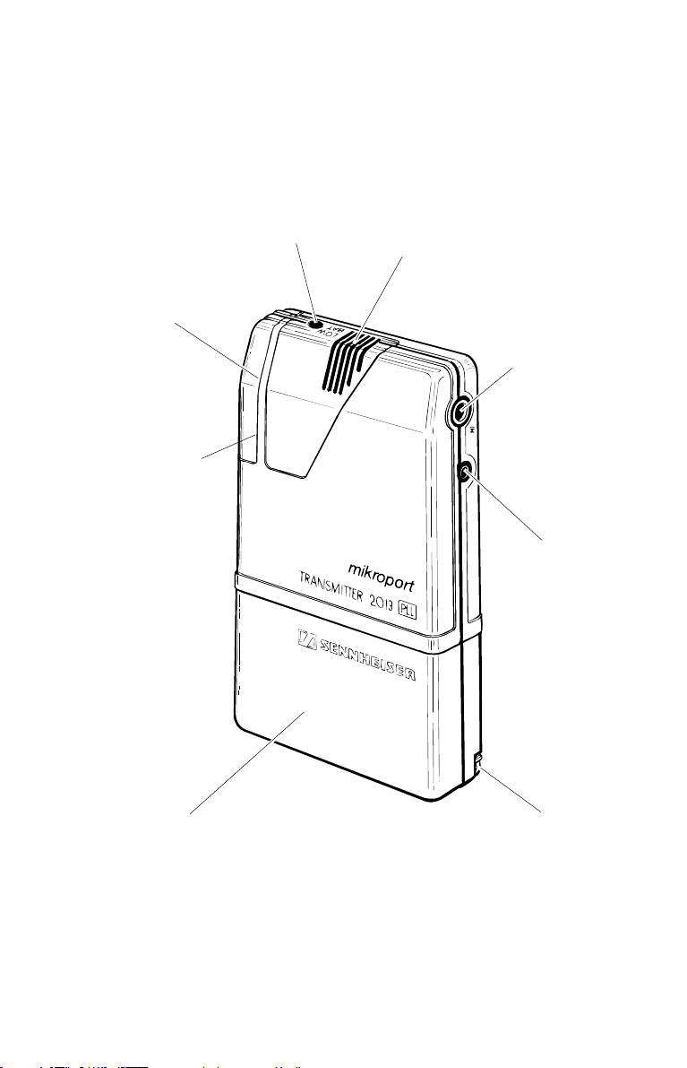
SK 2013 PLL
BATTERY INDICATOR LAMP
LOCKABLE
COVER
CHANNEL
SELECTOR SWITCH
FOR UP TO 16
FREELY-SELECTABLE
FREQUENCIES
BUILT-IN
MICROPHONE
CONNECTION FOR
ADDITIONAL DEVICES,
E.G. CASSETTE
RECORDER
Input
CONNECTION
FOR ADDITIONAL
MICROPHONE
MKE 2013
INTERCHANGEABLE
STANDARD OR
RECHARGEABLE
BATTERY PACK
CHARGING CONTACT FOR CHARGING
IN CHARGING UNIT L 2013 (ONLY ON
RECHARGEABLE BATTERY PACK)
2.2
Page 4

System description
2.4 Units
2.4 Operating principle
2.5 Common characteristics
2.6 Initial operation
2.6 Inserting battery pack
2.6 Operation with rechargeable batteries
2.6 Switching on / Securing on clothing
2.6 List of available transmission/reception ranges
2.7 Frequency selection
2.7 Setting channels on transmitter and receiver
Receiver EK 2013 PLL
2.8 Connection possibilities on receiver
2.8 Integrated antenna
2.8 Operation on hearing aid with audio input
2.8 Operation on hearing aid without audio input
2.8 Operation with headphones
2.9 Lockable cover
2.9 Automatic fade-in and microphone adjustment on receiver
2.10 Setting automatic fade-in
2.10 Switching automatic fade-in and built-in microphone on/off
2.11 Indicator lamps on receiver EK 2013 PLL
2.11 Automatic fade-in, green LED
2.11 Squelch and battery check, red LED
Transmitter SK 2013 PLL
2.12 Connection possibilities
2.12 Indicator lamps
2.13 Setting microphone sensitivity
2.10 Accessories
2.14 Cables
2.15 Technical data - SK 2013 PLL
2.16 Technical data - EK 2013 PLL
2.3
Page 5

System 2013
The System 2013 PLL enables the successful integration of people with hearing problems
in schools and universities, at the workplace and during leisure activities.
The design and control details have been optimally adapted to this target group.
Operation is simple and easy to learn. The units are small, light-weight and inconspicuous.
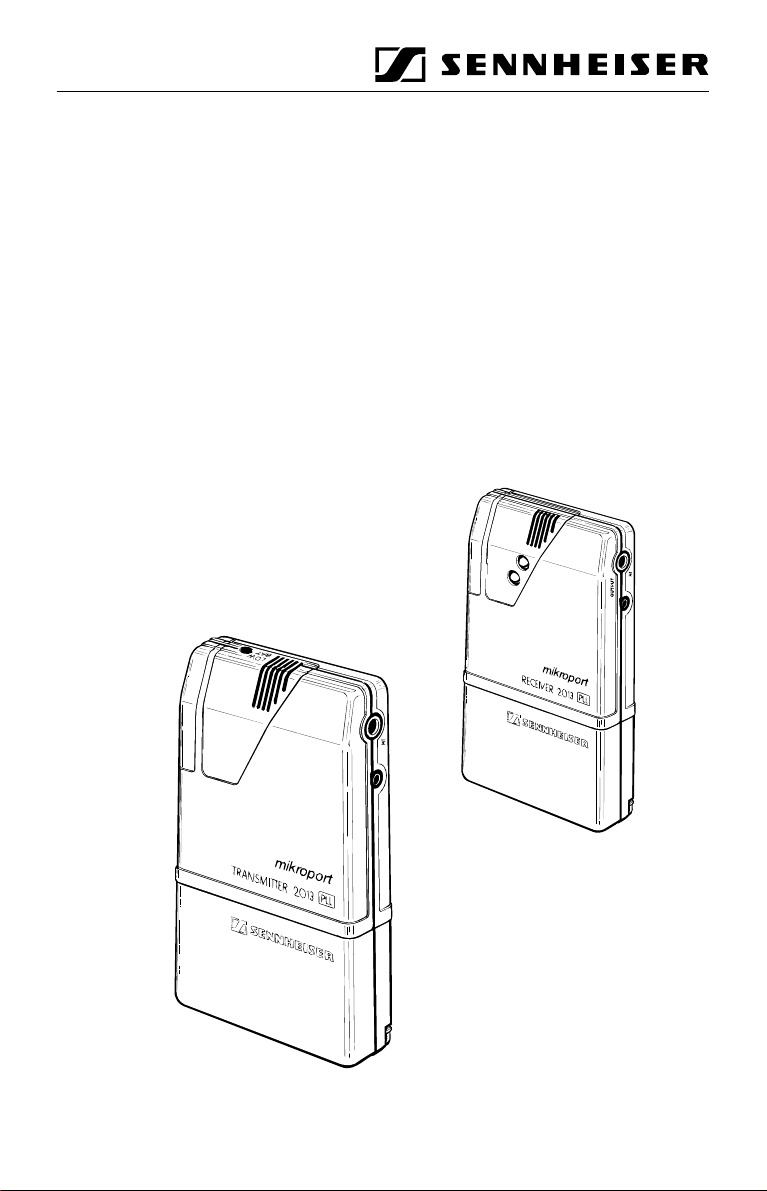
Units
• Transmitter SK 2013 PLL for the speaker
• Receiver EK 2013 PLL for the hearing impaired
Operating principle
The speaker, e.g. the instructor, wears the Transmitter SK 2013 PLL. The hearing
impaired person wears the Receiver EK 2013 PLL. Headphones or a connecting cable to
hearing aids can be connected to the EK 2013 PLL. The student can now hear the
instructor as if he/she were sitting directly next to him/her - without wires and with
retained freedom of movement. For the time during which the instructor speaks, the
surrounding noises are considerably reduced. If the instructor is not speaking, the hearing
aid or the microphone built into the EK 2013 PLL is completely effective; now fellow
students can be heard. Yet the dialogue between the instructor and the student is always
given priority.
The System 2013 PLL also remains a dependable aid under difficult conditions. The
transmitting output reaches over great distances. Loud secondary noises and poor room
acoustics can be faded out with the use of the additional microphone MKE 2013 on the
Transmitter SK 2013 PLL. The wide range of accessories allows connection of the
receiver to nearly any type of hearing aid; the connection to the hearing aid can be either
electrical or inductive.
2.4
Page 6
SK 2013 PLL
or EK 2013 PLL
The Transmitter SK 2013 PLL and the Receiver EK 2013 PLL are supplied with current
by attachable RECHARGEABLE battery packs, type BA 2013. These battery packs are
charged over night separately or in conjunction with their unit in the Dual Charging Unit
L 2013. One battery pack has sufficient power for a normal working day (up to 12 hours).
It is completely recharged over night.
Standard (non-rechargeable) battery packs allow operation far from an electrical system
(maximum operating time: over 40 hours). They replace the rechargeable battery packs.
Common characteristics for transmitter and receiver
• up to 40 hour operating time, interchangeable standard and
rechargeable battery pack
• built-in microphone in transmitter and receiver
B 2013
BA 2013
2.5
Page 7

Initial operation
On
OFF
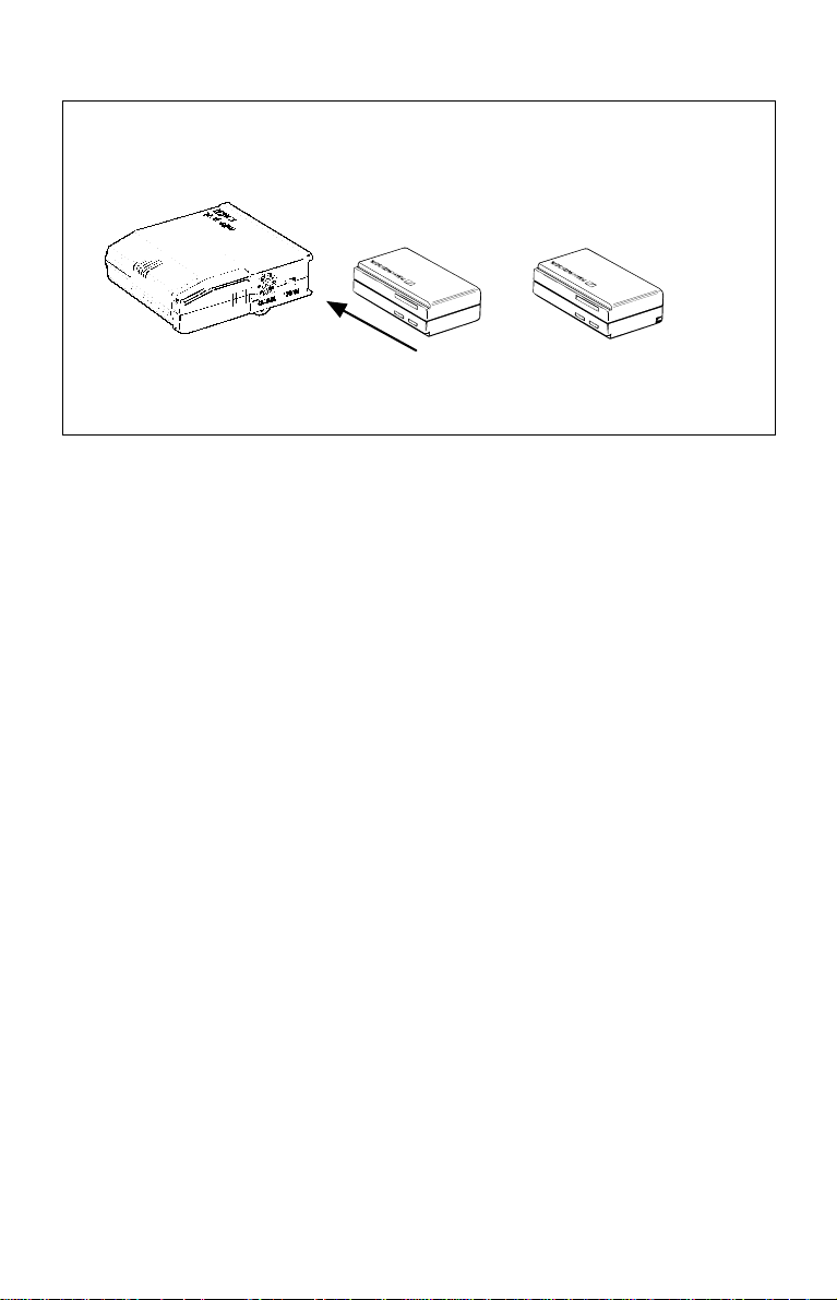
Inserting battery pack
Two batteries (AA size) are inserted in the removable base compartment (same for
transmitter and receiver). The battery compartment lock (see diagram) can be easily
pressed open with a screwdriver or a similar pointed instrument.
Operation with rechargeable batteries
The RECHARGEABLE battery pack BA 2013 is recommended for daily use. The
battery pack is slid onto the base of the transmitter or receiver in the same manner as the
standard battery pack. The RECHARGEABLE batteries are recharged in the Dual
Charging Unit L 2013.
DEUTSCH
DEUTSCH
english
Français
Italiano
Switching on/securing on clothing
To switch the unit on, slide the ON/OFF switch on the transmitter or receiver downward.
The transmitter or receiver is secured on the body with the neck strap and the retaining
plate. The transmitter or receiver can also be clipped onto a shirt or belt with the attached
clip.
List of available transmission/reception ranges
EK/SK 2013-6-D 8 m frequency band 36.64-37.98 MHz
EK/SK 2013-6-1 8 m frequency band 30-36 MHz
EK/SK 2013-6-2 8 m frequency band 35-40 MHz
EK/SK 2013-6-3 8 m frequency band 39-45 MHz
EK/SK 2013-8 4 m frequency band 72.025-75.975 MHz
EK/SK 2013-9 2 m frequency band 173.350-175.02 MHz
2.6
Español
Svenska
Nederlands
Page 8

Frequency selection
D
Setting channels on transmitter and receiver
The transmission frequencies are set with the rotary switch (D) on the transmitter and
receiver. The assignment of a switch position to a frequency is listed on the back of the
unit on the information plate. Depending on the model, up to 16 frequencies are available.
This allows multi-channel operation, e.g. in schools.
Important information:
• The transmitter and receiver of one transmission unit must be
set to the same frequency!
• One transmitter can be used with several receivers set to the same frequency.
• One receiver cannot be used with several transmitters set to one frequency! This
type of incorrect setting can be noticed from crackling and chirping noises at the receiver.
2.7
Page 9

Receiver EK 2013 PLL
3.5 mm dia. Stereo jack
High-level output (2 x 0.7 V / 32 Ω)
2.5 mm dia. Stereo jack
Low-level output (2 x 3 mV / 2 kΩ)
Characteristics
• Up to 16 PLL-controlled frequencies
• Highly visible indicator lamp for all important functions
• Child-proof due to lockable cover of adjustment elements
• Integrated automatic fade-in feature
• Built-in microphone. The receiver becomes a hearing aid
if required. - even without additional accessories -
Connection possibilities on receiver EK 2013 PLL
There are two stereo cinch jacks on the left side of the unit: a large jack with 3.5 mm dia.
and a small jack with 2.5 mm dia.
Only stereo cinch plugs may be inserted into the two jacks! Mono plugs lead to
malfunction or short circuit. Mono headphones must be equipped with stereo cinch plugs.
Integrated antenna
In both jacks the inserted cable is simultaneously used as an antenna. Only use original
Sennheiser cables!
Operation on hearing aid with audio input
The small jack (2.5 mm dia.) supplies the output signal for a hearing aid with an audio
input. Hearing aid dealers carry suitable connection cables.
(also see „CABLES“)
Operation on hearing aid without audio input
The „Tele-Loop“ ETZ 1011 or the Induction Disc EZI 120 for hearing aids without an
audio input is connected to the large jack (3.5 mm dia.).
Operation with headphones
Stereo headphones (impedance > 32 Ω) are connected to the large jack.
2.8
Page 10

M
S
Lockable cover on receiver
In order to reach the operating elements, a slide (S) is located on the right side of the unit.
This protects the operating elements against unauthorized or accidental use. It is secured
with a set screw (M), which is screwed in completely in order to open the slide.
After removing the slide two potentiometers are accessible:
• The lower potentiometer (P1) adjusts the receiver volume, i.e. regulates the volume
of the signal from the speaker.
• The upper potentiometer (P2) adjusts the basic volume of the built-in microphone.
Automatic fade-in and microphone adjustment
The receiver is equipped with an automatic fade-in feature. The connected hearing aid
microphone or the microphone built into the receiver are turned down for the duration
of speech transmission. This enables the signal of the speaker to be given preference at the
wearer of the receiver.
In addition, the automatic fade-in is complimented by a speech filter. As a result,
disturbing noises (doors banging etc.) do not trigger the automatic fade-in feature.
The automatic fade-in and the basic volume of the faded-in microphone can be set
separately.
2.9
Page 11

2
3
1
4
2
3
1
4
s1 s2
ON
Off
s
Off
P1
e
P2
ON
Setting automatic fade-in
This adjustment is made exclusively by the hearing aid dealer!
An adjuster (E) for the reduction depth of the automatic fade-in is located at the top behind
a hole in the housing. It can be turned with a 1.6 mm dia. screwdriver. Turning clockwise
increases the reduction depth of the connected hearing aid microphones.
Switching automatic fade-in and built-in microphone on/off
This adjustment is made exclusively by the hearing aid dealer!
Two toggle switches (S1/2) are accessible in the unit between the potentiometers for
switching on the automatic fade-in and microphone. They can be actuated with a small
screwdriver (2.6 mm).
• If the switch (S2) is tipped toward the back of the unit, the automatic fade-in
feature is switched on.
• If the switch (S1) is tipped toward the upper side of the unit, the built-in microphone
is switched on.
(The EK 2013 PLL is delivered with this setting).
2.10
Page 12

Indicator lamps on the receiver EK 2013 PLL
l1
l2
Two LED indicator lamps are located on the front of the unit.
Automatic fade-in, green led
L1 indicates that the acoustic signal is being correctly transmitted. If it lights up, the
automatic fade-in feature is activated. The transmission path has preference over the
surrounding noises transmitted by the built-in microphone.
In addition, L1 also serves as an adjustment aid for the microphone sensitivity at the
Transmitter SK 2013 PLL. (Also see Page 14)
Squelch and battery check, red led
L2 has the dual function „squelch indicator“ (activated squelch) and „LowBat“
indicator for battery check with tendency recognition:
• constant red light Squelch switched on = no reception
• flashing red light slow flashing: The battery voltage is dropping!
rapid flashing: The battery voltage is no longer
Both indicator lamps are arranged on the front of the receiver so that they can also be
dependably seen over a greater distance by the person equipped with the transmitter.
In this way it is easy to ascertain whether the speech connection exists.
2.11
However, there is still contact.
The RECHARGEABLE or standard
battery pack must be changed in
approx. 15 minutes.
sufficient for operation. ATTENTION:
The receiver is not functioning!
Page 13

Transmitter SK 2013 PLL
m
l3
Connection possibilities
Either the built-in electret microphone can be
used or the separate microphone MKE 2013 (see
also „ACCESSORIES“ on Page 19) connected
to the 2.5 mm dia. cinch jack (B1).
MICROPHONE MKE 2013
b1
b2
b1
25 cm
The 3.5 mm dia cinch jack (B2) is available for the connection of high-level sound sources,
such as tape recorders, TV and Hi-Fi components.
The connection cable of the connected additional microphone MKE 2013 acts as an
antenna. If the additional microphone MKE 2013 is not used, the included additional
antenna must be inserted in the microphone jack.
Indicator lamps
The transmitter is equipped with a red indicator LED (L3) for monitoring the battery
output. The end of the operating period is announced with flashing approx. 15
minutes before the end of operation, so that there is sufficient time to replace the
RECHARGEABLE or standard battery pack.
2.12
Page 14

R
Setting microphone sensitivity on transmitter SK 2013 PLL
The microphone sensitivity should be set high enough on the regulator (R) that, on the
one hand, the green LED on the Receiver EK 2013 PLL does not go out during normal
speaking and, on the other hand, low enough that normal surrounding noise does not
activate the LED display.
The optimum setting is usually between 5 and 7.
2.13
Page 15

Accessories
EZU 2013 Neck strap with carrying plate for simple, safe securing on body
EZU 2013-1 Waist belt for use with neck strap (Art. No. 93439)
L 2013 Automatic charging unit for charging 2 RECHARGEABLE battery packs
NT 2013 Power supply unit for charging unit, operates on 230 V. (Art No. 03433)
NT 2013-120 Power supply unit for charging unit, operates on 120 V. (Art. No. 03434)
NT 2013-UK Power supply unit for charging unit, operates on 240 V (GB).
MKE 2013 Clip-on microphone for Transmitter SK 2013 PLL (Art. No. 03323)
BA 2013 Additional rechargeable battery pack (Art. No. 03436)
B 2013 Battery box, operation of system far from charging possibility
(Art. No. 03438)
BA 2013 alone or with Transmitter/Receiver SK/EK 2013 PLL.
(Art. No. 03324)
(Art. No. 03435)
(Art. No. 03437)
Cables
KAB - 1 E Binaural connection cable for two hearing aids with audio input.
Length: 80 cm (Art. No. 03440)
KAB - E Binaural connection cable for two hearing aids with audio input.
KA - 1 E Monaural connection cable for one hearing aid with audio input. Length:
KA - E Monaural connection cable for one hearing aid with audio input. Length:
KAB - 1K Binaural connection cable with two Sennheiser mini-plugs for connection
KAB - K Binaural connection cable with two Sennheiser mini-plugs for connection
KA - 1 K Monaural connection cable with one Sennheiser mini-plug for connection
KA - K Monaural connection cable with one Sennheiser mini-plug for connection
Length: 40 cm (Art. No. 03441)
80 cm (Art. No. 03442)
40 cm (Art. No. 03443)
of Sennheiser headphones. Length: 80 cm (Art. No. 03444)
of Sennheiser headphones. Length: 40 cm (Art. No. 03445)
of Sennheiser headphones. Length: 80 cm (Art. No. 03446)
of Sennheiser headphones. Length: 40 cm (Art. No. 03447)
2.14
Page 16

Technical data
Transmitter SK 2013 PLL
Frequency range SK 2013-6-D 8 m frequency band 36.64-37.98 MHz
Frequency preparation Phase Lock Loop (PLL) Technique, 16 channels
Frequency constancy ± 2 kHz, -10° to +55° C
HF output power 10 mW
HF radiation power 1 mW
Perturbing radiation power < 4 nW
Modulation type FM
Rated lift/peak lift ± 8 kHz / ± 10 kHz
Channel grid/switching band width SK 2013-6-D 40 kHz / 2.34 MHz
LF transmission range 40 - 16,000 Hz
Nonlinear distortion factor
at 1 kHz and rated lift typ. 1 %
LF sensitivity min./max. 4 mV/44 mV - Microphone input
Input resistance 3kΩ - Microphone input
SK 2013-6-1 8 m frequency band 30-36 MHz
SK 2013-6-2 8 m frequency band 35-40 MHz
SK 2013-6-3 8 m frequency band 39-45 MHz
SK 2013-8 4 m frequency band 72.025-75.975 MHz
SK 2013-9 2 m frequency band 173.350-175.02 MHz
SK 2013-6-1 40 kHz / 2 MHz
SK 2013-6-2 40 kHz / 2 MHz
SK 2013-6-3 40 kHz / 2 MHz
SK 2013-8 25 kHz / 4 MHz
SK 2013-9 25 kHz / 2 MHz
150 mV/2.65 V - Aux. input
100 kΩ - Aux. input
Operating voltage 2.4 V
Current consumption approx. 55 mA
Operating time > 12 hours with RECHARGEABLE
Battery check red LED for operating voltage < 2.2 V
Dimensions 18 x 58 x 95 mm
Weight (incl. B 2013) approx. 130 g
German ZZF Certification No. A 014 926 B ME (only -6)
Scope of delivery 1 Transmitter SK 2013 PLL
Also included in the System 2013 (set of transmitter and receiver) are two securing plates
with retaining straps. The System 2013 is supplied in a sturdy transport and storage
carrying case.
2.15
battery pack BA 2013
> 36 hours with 2 x Alkaline AA cells in B 2013
1 Battery compartment B 2013
1 Projection antenna 44891
Page 17

Technical data
Receiver EK 2013 PLL
Frequency range EK 2013-6-D 8 m frequency band 36.64-37.98 MHz
EK 2013-6-1 8 m frequency band 30-36 MHz
EK 2013-6-2 8 m frequency band 35-40 MHz
EK 2013-6-3 8 m frequency band 39-45 MHz
EK 2013-8 4 m frequency band 72.025-75.975 MHz
EK 2013-9 2 m frequency band 173.350-175.02 MHz
Frequency preparation Phase Lock Loop (PLL) Technique, 16 channels
Modulation type FM
Rated lift/peak lift ± 8 kHz / ± 12 kHz
Channel grid/switching band width EK 2013-6-D 40 kHz / 2.34 MHz
Sensitivity
(measured via artificial antenna) typ. 0.5 µV for 26 dB S/N
Neighboring channel selection typ. 70 dB
LF transmission range 40 - 16,000 Hz
Nonlinear distortion factor
at 1 kHz and rated lift typ. 1 %
LF output 1: 3.5 mm dia. jack High: 2 x 0.7 V / 32 U
LF output 2: 2.5 mm dia. jack Low (hearing aids): 2 x 3 mV / 2 kΩ
EK 2013-6-1 40 kHz / 2 MHz
EK 2013-6-2 40 kHz / 2 MHz
EK 2013-6-3 40 kHz / 2 MHz
EK 2013-8 25 kHz / 4 MHz
EK 2013-9 25 kHz / 2 MHz
Impedance at LF output 2
for connection of hearing aids
in normal operation 3 kΩ
with activated automatic fade-in 80 U to 1 kU adjustable
Operating voltage 2.4 V
Current consumption approx. 45 mA
Operating time > 14 hours with RECHARGEABLE battery
pack
BA 2013
> 40 hours with 2 x Alkaline AA cells in B 2013
Battery check red LED for operating voltage < 2.2 V
Dimensions 18 x 58 x 95 mm
Weight (incl. B 2013) approx. 130 g
German ZZF Certification No. A 014 926 B ME (only -6)
Scope of delivery 1 Receiver EK 2013 PLL
Not responsible for errors. Subject to change without notice.
1 Battery compartment B 2013
2.16
Page 18

Sennheiser electronic KG · D-30892 Wedemark Printed in Germany
Telephone (0 51 30) 6 00-0 · Telex 9 24 623 · Fax (0 51 30) 63 12 Publ. 7/93 44925 /A 04
 Loading...