

Page 1
9Nnl131N"S9NnN31O38
301n9S,H3sn
101dIN3,O3001N
1~H39Z13N
AlddnsH3MOd
!Jn3133S NOIHllN31N1l"
H:lSI:lHNN:lS[Zj
~~
817d 9~NZII\I
n-817d9~NZII\I
Page 2
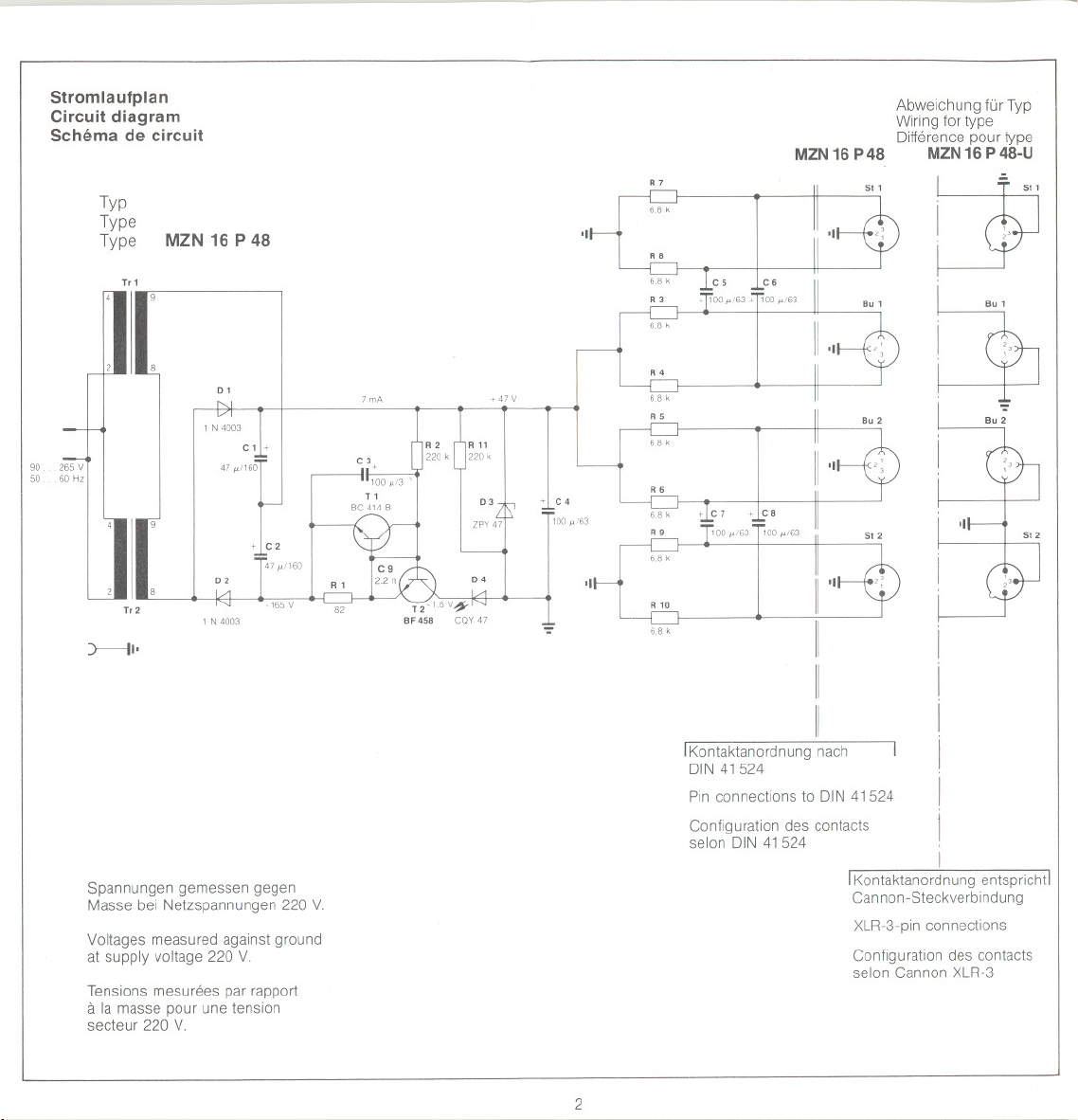
Stromlaufplan
Circuit diagram
Schema de circuit
Typ
Type
Type
MZN 16 P 48
T.1
Abweichung für Typ
Wiring for type
MZN 16 P 48 MZN 16 P 48-U
R7
6.8 k
'I
RB
C6
68 k
Difference pour type
~
LY
9050265 V
60 Hz
01
1 N 4003
C 11+
02
I R 1
T.2
1 N 4003
:::lc
-165 V 82
) 11'
Spannungen gemessen gegen
Masse bei Netzspannungen 220 V-
Voltages measured against ground
at supply voltage 220 V-
Tensions mesurees par rapport
a la masse pour une tension
secteur 220 V-
7 mA
C3
+
100 M13 '
T 1
BC 414 B
IC9
2.2 n
R11
220 k
zpy 47
03
+ 47V
+1 C4
100 M/63
'::'
R4
6.8 k
R5
6.8 k
R6
100 M/63
6.8 k
S. 2
'I
R 10
6.8 k
r
I[
11
11
IKontaktanordnung nach I
DIN 41524
Pin connections to DIN41524
Configuration des contacts
selon DIN 41524
IKontaktanordnung entspricht!
Can non-Steckverbindu ng
XLR-3-pin connections
Configuration des contacts
selon Cannon XLR-3
1
I
2
Page 3
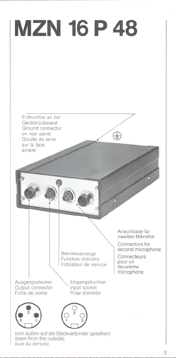
MZN 16P 48
Erdbuchse an der
Geräterückwand
Ground connector
on rear panel
Douille de terre
sur la face
arriere'
Betriebsanzeige
Function indicator
Indicateur de service
Ausgangsstecker
Output connector
Fiche de sortie
3 1
~
(von außen auf die Steckverbinder gesehen)
(seen from the outside)
(vue du dehors)
Eingangsbuchse
Input socket
Prise d'entree
1 3
~
Anschlüsse für
zweites Mikrofon
Connectors for
second microphone
Connecteurs
pourun
deuxieme
microphone
3
Page 4

BEDIENUNGSANLEITUNG
MZN 16P 48-U
Erdbuchse an der
Geräterückwand
Ground connector
on rear panel
Douille de terre
sur la face
arriere
Anschlüsse für
zweites Mikrofon
Connectors for
Betriebsanzeige
Function indicator
Indicateur de service
second microphone
Connecteurs
pourun
deuxieme
microphone
MZN 16 P 48, MZN 16 P 48-U
Lieferumfang: 1Netzgerät
Das Netzgerät MZN 16 P 48 und seine Variante MZN 16 P 48-U
dienen zum Betrieb zweier Kondensatormikrofone mit 48-V-Phantom-
speisung nach DIN 45596.
Das Gerät ist schutzisoliert und arbeitet ohne Umschaltung an
Wechselspannungen zwischen 95 V und 265 V. Es werden zwei
Netztransformatoren verwendet. Diese sind so angeordnet, daß
sich eine Kompensation des magnetischen Streufeldes im Bereich
der Verdrahtung ergibt, die die Tonfrequenz führt. Das Gerät enthält
keine Sicherungen, da die beiden Netztransformatoren dauerkurz-
schlußfest sind. Die Betriebsbereitschaft wird durch eine Leucht-
diode an der Buchsenseite des Gerätes angezeigt. Die Ausgänge
sind dauerkurzschlußfest. Der dem Gerät insgesamt entnommene
Gleichstrom wird elektronisch auf 6,5 mA begrenzt.
Ausgangsstecker
Output connector
Fiche de sortie
n
~
(von außen auf die Steckverbinder gesehen)
(seen from the outside)
(vue du dehors)
4
Eingangsbuchse
Input socket
Prise d'entree
0
\JU
Ausführungen
MZN 16 P 48 (Art.-Nr. 1240)
Mit 3pol. verschraubbaren Steckverbindern nach DIN 41524.
MZN 16 P48 U (Art.-Nr. 1241)
Mit 3pol. XLR-Steckverbindern.
Anschlußhinweise
Die Signalausgänge des Netzgerätes können sowohl an symme-
trische als auch an unsymmetrische Mikrofoneingänge ange-
schlossen werden.
5
Page 5

Technische Daten
USER'SGUIDE
MZN16P48
Netzspannung
Leistungsaufnahme
Leerlauf-
Ausgangsgleichspannung
Max.zulässiger Befriebs-
Ausgangsgleichstromje Kanal 3 mA
Fremdspannung,gemessen
an Abschlußwiderstand200 Q
Buchse
PassenderAnschlußstecker
Stecker
PassendeAnschlußkupplung
AbmessungendesGehäuses
Gewicht
. 95 265 VI
50 60 Hz
ohne Umschaltung
ca.3 VAbei 220V
48 V j: 2 V
< 4 ~V
1~ + Speisespannung
2~ - Gehäuse, Schirm
3 ~ + Speisespannung
z. B. T 3260 001
1 ~NFI+I
2 ~ Gehäuse, Schirm
3~ NF I-I
z. B T 3261 001
168 x 120 x 50 mm
ca. 1100 9
MZN 16 P48-U
95. .265VI
50 60Hz
ohne Umschaltung
ca.3 VAbei 220V
48 V j: 2V
3 mA
<4 ~V
1~ - Gehäuse, Schirm
2 ~ + Speisespannung
3~ + Speisespannung
z. B. Cannon XLR-3-12 C,
Switchcraft A 3 M
1~ Gehäuse,Schirm
2~NF(+)
3 ~ NF H
z. B. Cannon XLR-3-11 C,
SwitchcraftA3 F
168x 120 x 50 mm
ca. 1100 9
MZN 16P48,MZN 16P 48-U
Extend of delivery: 1 power supply
I
Anderungen, vor ailem zum technischen Fortschntt, vorbehaiten
6
The power supply MZN 16 P 48 and its complementary model
MZN 16 P 48-U serve to feed two transistor-condenser-micro-
phones, 48-V-phantom-powered according to DIN 45596.
The unit is double insulated and can be powered from AC-lines
between 95 V and 265 V. It contains two mains transformers. They
are mounted in a way that the magnetic stray fields are compensat-
ed, which is of advantage especially in the areas of audio carrying
wiring. The mains transformers are short circuit proo!. The connec-
tor panel contains an LED which lights up when a microphone is
eonneeted. The supply outputs are short cireuit proof. The total
supply eurrent is eleetronieally limited to 6.5 mA.
)
Models
MZN 16 P 48 (Art.-No. 1240)
With screwable 3-pin conneetors aeeording to DIN 41524.
MZN 16 P48 U (Art.-No. 1241)
With 3-pin XLR-eonnectors.
Connecting the supply
The signal outputs may be conneeted to balaneed or unbalaneed
mierophone inputs.
7
Page 6

MODE D'EMPLOI
MZN 16 P48
Mains
Powereonsumplion
DC-outputvoltage
(no load eondltlon)
Max.eontinuousoutput
DC-eurrentper ehannel
Unweightednoise voltage
at200Q .
Femaleeonneetor
Corresponding eableeonneetor e. g. T3260001
Maleconneetor . 1~ audio(+)
Corresponding eable eonneetor e. g. T 3261001
Dimensions of housing
Welght
95 265 VI
50 60 Hz
(voltageseleetion
not neeessary)
approx.3 VAat 220 V
48:t 2V
3mA
< 4 ~V
1 = + supplyvoltage
2 ~ - housing,sereen
3 = + supply voltage
2 = houslng, sereen
3 ~ audio (-)
. 168x 120x 50 10m
appx. 11009
MZN 16 P48-U
95 265VI
50...60Hz
(voltageseleelion
not neeessary)
approx.3 VAal 220 V
48:t 2V
3mA
< 4 ~V
1 = - hausmg,sereen
2 ~ + supplyvoltage
3 = + supply vollage
e. g. Cannon XLR-3-12 C or
SWlteheratt A 3 M
1 ~ housing, sereen
2 = audio (+)
3 ~ audio (-)
e. g. Cannon XLR 3-11 C or
Switeheratt A 3 F
168 x 120 x 50 mm
appx. 11 00 9
i MZN 16 P 48, MZN 16 P 48-U
La livraison comprend: 1 alimentation secteur
reserve the righl to alter speeiflcations, especially wllh regard
We
10lechnleal Improvements.
8
L'alimentation secteur MZN 16 P 48 et sa variante MZN 16 P 48-U
servent a alimenter deux micros electrostatiques a alimentation fan-
töme 48 V selon DIN 45596.
L'appareil est a isolement de protection et fonctionne, sans
commutation, a des tension alternatives de 95 a 265 V. L'appareil
.contient deux transforrnateurs, disposes de maniere a compenser
le charnp de dispersion magnetique au voisinage des cables BF. 11
ne contient pas de fusibles, etant donne la resistance aux courts-
circuits permanente des transformateurs utilises, Le pret pour le
service est indique par la diode luminescente, Les sorties sont
resitants aux courts-circuits en perrnanence, Le courant total est
limite a 6,5 mA par un circuit electronique.
Modeles
MZN 16 P 48 (N° d'art. 1240)
Equipe des connecteurs tripolaires vissables selon DIN 41524.
MZN 16 P 48 U (N° d'art. 1241)
Equipe des connecteurs XLR tripolaire,
Connexion de I'alimentation secteur
On peut connecter les sorties de signal meme a des entrees micro
symetriques ou asymetriques,
9
Page 7

MZN 16 P48 MZN 16 P48-U
Tensionreseau
Consommationsursecteur
Tensioncontinue de sortie
avide 48:t 2V 48:t 2V
Courantcontinude sortle
max.parcanal
TenSionnon-ponderee,
mesureea200 Q < 4 V < 4 V
Plise
Fichede raccordappropriee p. ex.T 3260 001 p. ex. CannonXLR-3-12C,
Fiche
Pllsede raccordappropriee p.ex. T 3261001 p. ex. CannonXLR-3-11 C,
DimenSionsduboHler
POlds
265V 95. .265V
95
50 60 Hz
sanscommutatlon sanscommutation
env. 3VA pour220 V
3mA 3 mA
1 alimentation 1+)
2 boHierI-I, bllndage 2 alimentation1+1
3 alimentation 1+) 3 alimentationI+I
1 BFI+)
2 boitier, bllndage
3 BFI-) 3 BFI-I
168x 120 x 50 mm
. env. 1100 9 env. 1100 9
50
60 Hz
env. 3 VA pour 220 V
1 boitier, H, blindage
SWltchcraftA3 M
1 boitier, blindage
2BFI+I
SWltchclaftA 3 F
168x 120 x 50 mm
Modiflcatlons, surtout dans I'interet du progles technlque. leservees
10
Page 8

Sennheiser electronic GmbH & Co.KG
Telefon: 051 30 ! 6 00-0
Telefax: 05130! 600-300
D-30900 Wedemark
Printed in Germany Publ.11/85 18393/ AO2
 Loading...