

Page 1
Page 2
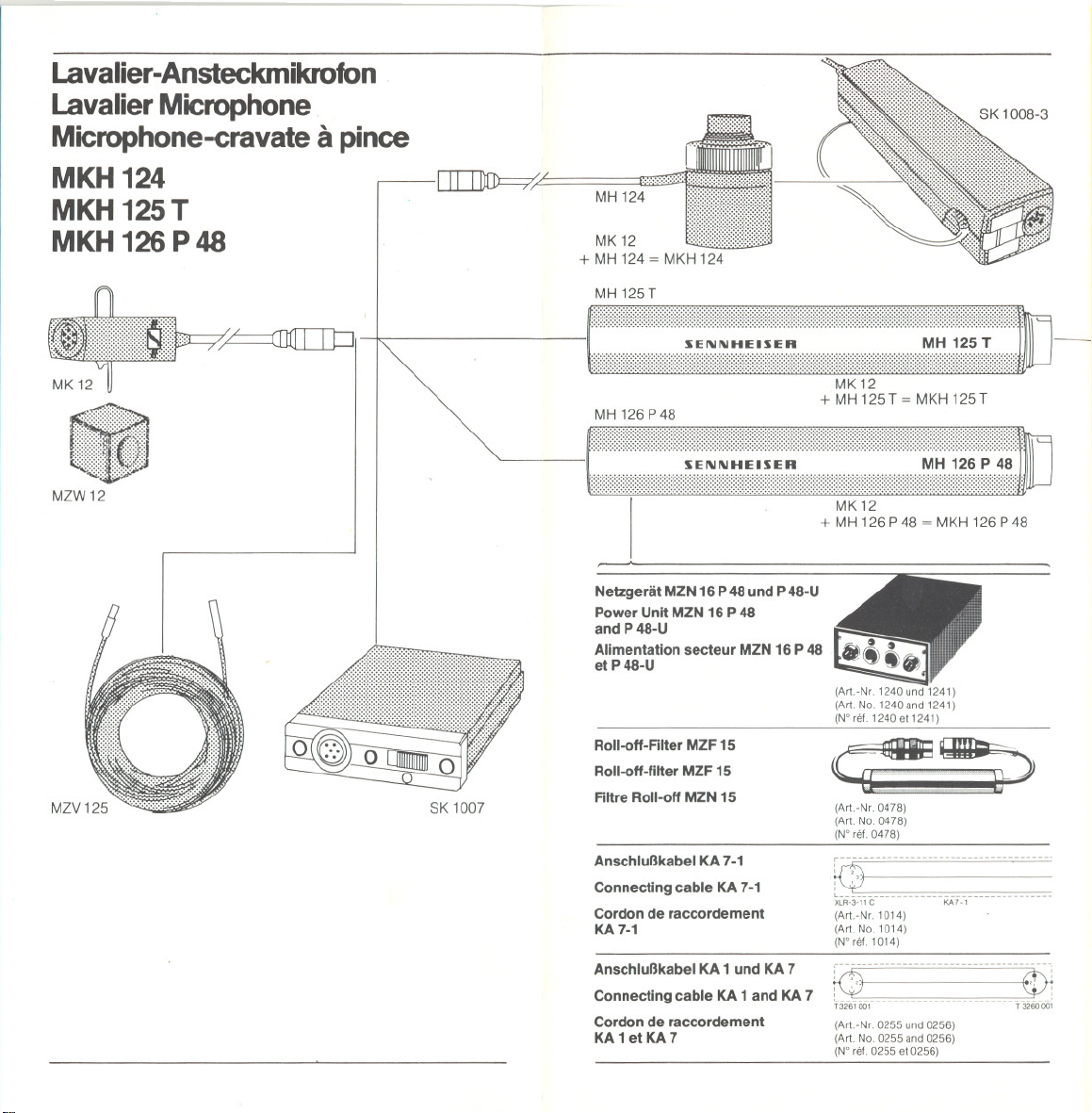
Lavalier-Ansteckmikrofon
LavalierMicrophone
Microphone-cravate apince
MKH124
MKH125 T
MKH126P48
MZW12
~
SK 1007
MH 124
MK12
+ MH124 = MKH 124
MH125T
SEI\II\IHEISER MH125 T
ttttttt:ttttttt:ttttttttttttttttttttttttttttt:ttttttt::
~
MH 126 P48
......................................................................................................
......................................................................................................
_:::::::::::::::::::::::::::::::::::::::::::::;:;:::::=:;:~::~::;:::::::::::::::::::::::::::::::::::=;:::::::::::::::::::::::::::~:::;:~~:::::::~:~:::.
.......................................................................................................
........................................................................................................
.......................................................................................................
........................................................................................................
......................................................................................................
......................................................................................................
......................................................................................................
......................................................................................................
I JJ
Netzgerät MZN 16 P 48 und P 48-U
Power Unlt MZN 16 P 48
and P 48-U
Alimentation secteur MZN 16 P 48
et P48-U
Roll-off-Filter MZF 15
Roll-off-filter MZF 15
Filtre Roll-off MZN 15
Anschlußkabel KA 7-1
Connecting cable KA 7-1
Cordon de raccordement
KA7-1
Anschlußkabel KA 1 und KA 7
Connectlng cable KA 1 and KA 7
Cordon de raccordement
KA1etKA7
" ,..",......................................................
MK12
+ MH 125 T = MKH 125 T
.....
MK12
........
+ MH 126 P48 = MKH 126 P48
(Art.-Nr. 1240 und 1241)
(Art. No. 1240and 1241)
(N°ref.1240et1241)
~"~
(Art.-Nr.0478)
(Art. No. 0478)
(N° rel. 0478)
tQ~--~ ~~--~~~~~~-:_mmnm_.
XLR.3.11 C KA7-1
(Art.-Nr.1014)
(Art. No. 1014)
(N°ret. 1014)
RD mnmnmnmmmnEDJ
T3261 001
(Art.-Nr. 0255 und0256)
(Art. No. 0255 and0256)
(W ret.0255ef0256)
non
---'3260001
.
Page 3
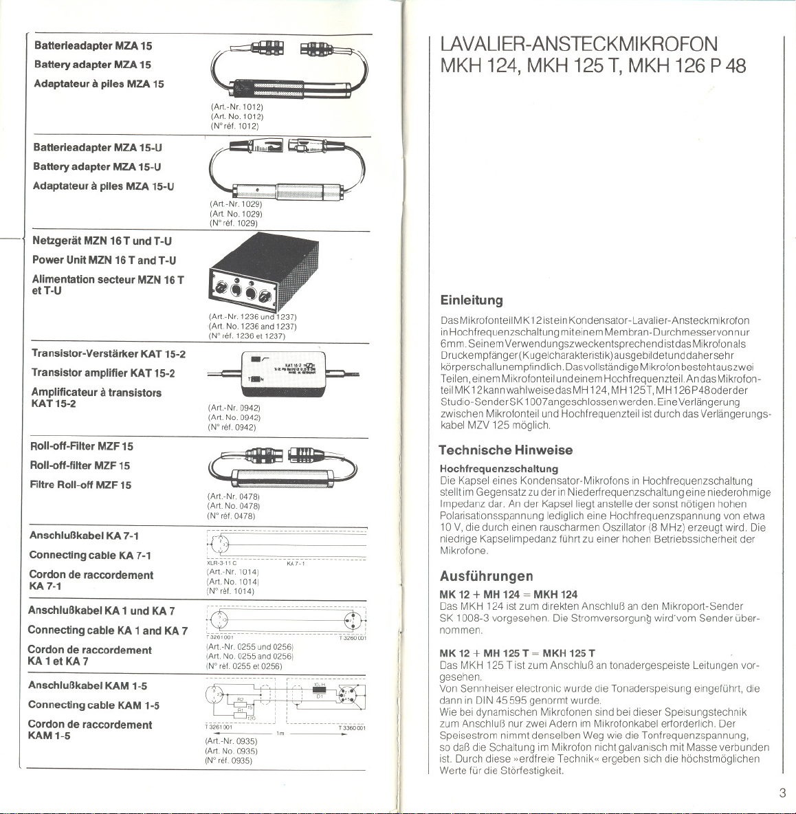
Batterieadapter MZA 15
Battery adapter MZA 15
Adaptateur a piles MZA 15
Batterieadapter MZA 15-U
Battery adapter MZA 15-U
Adaptateur a piles MZA 15-U
Netzgerät MZN 16 T und T-U
Power Unlt MZN 16 T and T-U
Alimentation secteur MZN 16 T
eH -U
Transistor-Verstärker KAT 15-2
Transistor amplifier KAT 15-2
Amplificateur a transistors
KAT15-2
Roll-oft-Filter MZF 15
Roll-oft-filter MZF 15
Filtre Roll-oft MZF 15
Anschlußkabel KA 7-1
Connecting cable KA 7-1
Cordon de raccordement
KA7-1
Anschlußkabel KA 1 und KA 7
Connecting cable KA 1 and KA 7
Cordon de raccordement
KA 1 et KA 7
Anschlußkabel KAM 1-5
Connecting cable KAM 1-5
Cordon de raccordement
KAM1-5
~
(Art.-Nr1012)
(Art. No. 1012)
(Wret.1012)
(Art.-Nr. 1029)
(Art No. 1029)
(N'rel.1029)
., t~~.;ß
r...
(Art.-Nr. 0942)
(Art No. 0942)
(N' rel. 0942)
. ... , '
~,..,~
(Art.-Nr.0478)
(Art. No. 0478)
(W rel. 0478)
t9_- --- ~- - - - ~ - - ~~- - - - - - - - - - - --
XLR-3-11C KA7-'
(Art-Nr 1014)
(Art No.1014)
(Wrel.1O14)
nn_nnnnnn-
:0 EDi
13261oo,n --_n_n'3260-00;
(Art.-Nr. 0255 und 0256)
(Art. No. 0255 and 0256)
(W rel. 0255 el 0256)
. R2 "",, D' "
c," U i :'L...
~!(nii--~
T 326' 001 -_nnn nn nT 336000'
(Art-Nr 0935)
(Art No.0935)
(W ret. 0935)
'co ::
'm
LAVALlER-ANSTECKMI KROFON
MKH 124, MKH 125 T, MKH 126 P48
Einleitung
DasMikrofonteil MK12istein Kondensator -Lavalier-Ansteckmikrofon
inHochfrequenzschaltung miteinem Membran-Durchmesservon nur
6mm. Seinem Verwendungszweckentsprechend istdas Mikrofon als
0 ruckempfänger( Kugelcharakte ristik)ausgebildet unddaherseh r
körperschallunempfindlich. Dasvollständige Mikrofon bestehtauszwei
Teilen, einem Mikrofonteil und einem Hochfrequenzteil. An dasMikrofon-
teil MK12kannwahiweisedasMH 124, MH125T, MH 126P480derder
Studio-Sender SK 1007 angeschlossen werden. EineVerlängerung
zwischen Mikrofonteil und Hochfrequenzteil istdurch das Verlängerungs-
kabel MZV 125 möglich.
Technische Hinweise
Hochfrequenzschaltung
Die Kapsel eines Kondensator-Mikrofons in Hochfrequenzschaltung
stellt im Gegensatz zu der in Niederfrequenzschaltung eine niederohmige
Impedanz dar. An der Kapsel liegt anstelle der sonst nötigen hohen
Polarisationsspannung lediglich eine Hochfrequenzspannung von etwa
10 V, die durch einen rauscharmen Oszillator (8 MHz) erzeugt wird. Die
niedrige Kapselimpedanz führt zu einer hohen Betriebssicherheit der
Mikrofone
Ausführungen
MK 12+ MH 124= MKH 124
Das MKH 124 ist zum direkten Anschluß an den Mikroport-Sender
SK 1008-3 vorgesehen. Die Stromversorgung wird'vom Sender über-
nommen.
MK12+ MH125T= MKH125T .
Das MKH 125 T ist zum Anschluß an tonadergespeiste Leitungen vor-
gesehen.
Von Sennheiser electronic wurde die Tonaderspeisung eingeführt, die
dann in DIN 45595 genormt wurde.
Wie bei dynamischen Mikrofonen sind bei dieser Speisungstechnik
zum Anschluß nur zwei Adern im Mikrofonkabel erforderlich. Der
Speisestrom nimmt denselben Weg wie die Tonfrequenzspannung,
so daß die Schaltung im Mikrofon nicht galvanisch mit Masse verbunden
ist. Durch diese »erdfreie Technik" ergeben sich die höchstmöglichen
Werte für die Störfestigkeit.
3
Page 4
Beim Anschluß der Sennheiser-Kondensator-Mikrofone wird ebenso
wie bei dynamischen Mikrofonen vom Prinzip der Spannungsanpassung
Gebrauch gemacht. Der Vorteil ist dabei, daß weder der Impedanz-
verlauf des Mikrofonausganges noch der des Verstärkereinganges
einen nennenswerten Einfluß auf den Gesamt-Frequenzgang haben.
Die Quellimpedanz der Sennheiser-Kondensator-Mikrofone mit Ton-
aderspeisung ist so klein (etwa 20 Q bei 1000 Hz), daß von der
Eingangsimpedanz des Verstärkers nur verlangt wird, daß sie mindestens
200 Q beträgt.
Die Sennheiser-Kondensator-Mikrofonegeben relativ hohe Spannungen
ab, bei maximalen Schalldrücken fast 1 V. Das hat den Vorteil, daß auch
bei großen Kabellängen eingekoppelte Störspannungen keine
Bedeutung erlangen. Weiterhin geht auch das Eigenrauschen des
Mikrofonverstärkers kaum noch in das Gesamtrauschen ein. Die
Mikrofone sind außerdem mit reichlich bemessenen Hochfrequenz-
siebgliedern ausgestattet, die dafür sorgen, daß keine Hochfrequenz-
spannungen auf die Mikrofonleitungen gelangen und die gleichzeitig
die Mikrofone gegen Hochfrequenzstörungen von außen schützen.
Es ist deshalb auch unter schwierigen Verhältnissen nicht notwendig,
besondere Maßnahmen, wie Doppelabschirmung der Leitungen und
hochfrequenzdichte Armaturen vorzusehen.
Sennheiser-Kondensator-Mikrofone sind nach DIN gepolt, d. h. bei
Auftreten eines Druckimpulses von vorn auf die Kapsel tritt an Stift 1 des
DIN-Steckers (bzw. Stift 2 des Cannon-Steckers) eine positive
Spannung gegenüber Stift 3 auf. Bei der Beschaltung der Anschlußstifte
der Verstärkereingänge sollte man daher auf die richtige Polung des
NF-Signals achten.
Anschluß an symmetrische Verstärker
In diesem Fall verbindet man das Mikrofon mit dem Netzgerät MZN 16 T
oder einem Batterieadapter MZA 15 und deren Ausgang wiederum
mit dem Verstärkereingang.
Anschluß an unsymmetrische Verstärker
Sehr häufig stehen nur unsymmetrische Verstärkereingänge zur Ver-
fügung, z. B. bei vielen HiFi-Tonbandgeräten. In d.iesem Fall erdet man
einen Punkt des Tonfrequenzausganges. Außerhalb der Studiotechnik
istdasaberin den meisten Fällen unkritisch, da der hohe Ausgangspegel
im Zusammenhang mit der niederohmigen Quellimpedanz des
Kondensatormikrofons für einen genügend großen Störabstand sorgt.
Es muß aber darauf geachtet werden, daß durch den Aufbau auf Stativen
usw. keine mehrfachen Erdungen entstehen.
Anschluß an Verstärker mit hoher Eingangsempfindlichkeit
Wenn der vorhandene Verstärker eine zu hohe Eingangsempfindlichkeit
besitzt, z. B. wenn er für niederohmige dynamische Mikrofone vor-
gesehen ist, kann es notwendig werden, den Pegel der Kondensator-
mikrofone mit Hilfe eines Spannungsteilers herunterzusetzen. Dieser
soll in der Mikrofonleitung am Verstärkereingang angeordnet werden.
Hierdurch wird in dem eigentlichen Mikrofonkreis der hohe Pegel
bewahrt, was sich günstig auf den Störabstand auswirkt.
Anschluß an Verstärker mit bestimmten Eingangsimpedanzen
Sennheiser Studio-Kondensator-Mikrofone können direkt an alle
Verstärker angeschlossen werden, deren Eingangswiderstand größer
als 200 Q ist. Das ist meist der Fall. Sollte dennoch ein Eingang mit
geringerer Impedanz vorliegen, so muß man mit einem geeigneten
Vorwiderstand dafür sorgen, daß das Mikrofon mindestens 200 Q
»sieht". Die dabei auftretende Spannungsteilung muß natürlich berück,
sichtigt werden.
Dieselbe Methode wird angewandt, wenn eine höhere Ausgangs-
impedanz des Mikrofons verlangt wird. Auch in diesem Fall kann man sich
durch Vorschalten eines entsprechenden Widerstandes helfen.
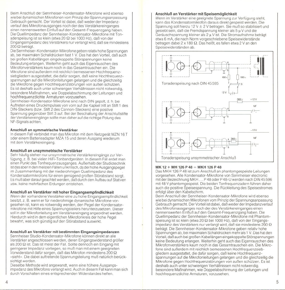
Anschluß an Verstärker mit Speisemöglichkeit
Wenn im Verstärker eine geeignete Spannung zur Verfügung steht,
kann das Kondensatormikrofon daraus direkt gespeist werden. Die
Spannung soll hierzu 12 V :!: 2 V betragen. Sie muß so stabilisiert und
gesiebt sein, daß die Fremdspannung kleiner als 5 [1V und die
Geräuschspannung kleiner als 2 [1V ist. Die Stromaufnahme beträgt
etwa 6 mA, die nach Norm vorgeschriebene Speisewiderstände
betragen dabei 2 x 180 Q. Das heißt, es fallen etwa 2 V an den
Speisewiderständen ab.
,--'
(';---7-'\a
" "
'-' "
. ~---'-I/b
180Q
Tonaderspeisung nach DIN45595 0
12V
0
+
' S
180Q
r~J
1
: I
: , '---
360Q +12V
,---T :
, ,
, ,
, ,
, ,
' ,
' ,
: ,
: L ,
/"\---7"\ a 360"
, , , ,
, , , ,
"r,'b
Tonaderspeisung unsymmetrischer Anschluß
NF
+' f::-
-12V
NF
I:;-
MK12 + MH 126P 48 = MKH 126 P 48
Das MKH 126 P48 ist zum Anschluß an phantomgespeiste Leitungen
vorgesehen. Alle Kondensator-Mikrofone von Sennheiser electronic
mit der Bezeichnung MKH... P48 oder P 48-U werden nach DIN45596
mit 48 V phantomgespeist. Die beiden Tonfrequenzadern führen daher
auch die positive Speisespannung. Die Rückleitung des Speisestromes
erfolgt über den Kabelschirm.
Beim Anschluß der Sennheiser-Kondensator-Mikrofone wird ebenso
wie bei dynamischen Mikrofonen vom Prinzip der Spannungsanpassung
Gebrauch gemacht. Der Vorteil istdabei, daßweder der Impedanzverlauf
des Mikrofonausganges noch der des Verstärkereinganges einen
nennenswerten Einfluß auf den Gesamt-Frequenzgang haben. Die
Quellimpedanz der Sennheiser-Kondensator-Mikrofone mit Phantom-
speisung ist so klein (etwa 20 Q bei 1000 Hz), daß von der Eingangs-
impedanz des Verstärkers nur verlangt wird, daß sie mindestens 200 Q
beträgt. Die Sennheiser-Kondensator-Mikrofone geben relativ hohe
Spannungen ab, bei maximalen Schalldrücken mehr als 1V. Das hat den
Vorteil, daßauch bei großen Kabellängen eingekoppelte Störspannungen
keine Bedeutung erlangen. Weiterhin geht auch das Eigenrauschen des
Mikrofonverstärkers kaum noch in das Gesamtrauschen ein. Die Mikro-
fone sind außerdem mit reichlich bemessenen Hochfrequenzsieb-
gliedern ausgestattet, die dafür sorgen, daß keine Hochfrequenz-
spannungen auf die Mikrofonleitungen gelangen und die gleichzeitig die
Mikrofone gegen Hochfrequenzstörungen von außen schützen. Es ist
deshalb auch unter schwierigen Verhältnissen nicht notwendig,
besondere Maßnahmen, wie Doppelabschirmung der Leitungen und
hochfrequenzdichte Armaturen, vorzusehen.
4 5
Page 5
Sennheiser-Kondensator-Mikrofone sind nach DIN gepolt, d. h. bei
Auftreffen eines Druckimpulses von vorn aufdie Kapsel tritt an Stift 1des
DIN-Steckers (bzw. Stift 2 des Cannon-Steckers) eine positive Spannung
gegenüber Stift 3 auf. Bei der Beschaltung der Anschlußstifte der Ver-
stärkereingänge sollte man daher auf die richtige Polung des NF-Signals
achten.
Anschluß an symmetrische Verstärker
Phantomgespeiste Mikrofone müssen grundsätzlich an symmetrisch-
erdfrei beschaltete, also mit einem Eingangstransformator versehene,
Eingänge angeschlossen werden. In diesem Fallverbindet man das
Mikrofon mit dem Netzgerät MZN 16 P 48 bzw. MZN 16 P 48-U (siehe
Zubehör) und deren Ausgang wiederum mit dem Verstärkereingang.
Anschluß an unsymmetrische Verstärker
Sollen phantomgespeiste Mikrofone über das entsprechende Netzgerät
an unsymmetrisch beschaltete Geräteeingänge angeschlossen werden,
so ist generell ein Übertrager zwischenzuschalten. Hierbei kann dann
gleichzeitig durch richtige Wahl des Übersetzungsverhältnisses die
geeignete Spannungsanpassung gemacht werden. Die Sekundärseite
des Ubertragers kann dann unsymmetrisch mit dem Geräteeingang
verbunden werden.
Anschluß an Verstärker mit hoher Eingangsempfindlichkeit
Wenn der vorhandene Verstärker eine zu hohe Eingangsempfindlichkeit
besitzt, z. B.wenn erfürniederohmigedynamische Mikrofonevorgesehen
ist, kann es notwendig werden, den Pegel der Kondensatormikrofone
mit Hilfe eines Spannungsteilers herunterzusetzen. Dieser soll in der
Mikrofonleitung am Verstärkereingang angeordnet werden. Hierdurch
wird in dem eigentlichen Mikrofonkreis der hohe Pegel bewahrt, was sich
günstig auf den Störabstand auswirkt.
Anschluß an Verstärker mit bestimmten Eingangsimpedanzen
Sennheiser Studio-Kondensator-Mikrofone können direkt an alle Ver-
stärker angeschlossen werden, deren Eingangswiderstand größer als
200 Q ist. Das ist meist der Fall. Sollte dennoch ein Eingang mit geringerer
Impedanz vorliegen, so muß man mit einem geeigneten Vorwiderstand
dafür sorgen, daß das Mikrofon mindestens 200 Q »sieht«. Die dabei
auftretende Spannungsteilung muß natürlich berücksichtigt werden.
Dieselbe Methode wird angewandt, wenn eine höhere Ausgangs-
impedanz des Mikrofons verlangt wird. Auch in diesem Fall kann man sich
durch Vorschalten eines entsprechenden Widerstandes helfen.
Anschluß an Verstärker mit Speisemöglichkeit
Wenn im Verstärker eine geeignete Spannung zur Verfügung steht, kann
das Kondensatormikrofon daraus direkt gespeist werden. Die Spannung
soll hierzu 48 V :t 12 V betragen. Sie muß so stabilisiert und gesiebt
sein, daß die Fremdspannung kleiner als 1 mV ist. Die Stromaufnahme
von Sennheiser-Kondensator-Mikrofonen MKH . ..P48 liegt bei ca. 2 mA.
Die nach Norm vorgeschriebenen Speisewiderstij,nde betragen dabei
2 x ca. 6,8 Q. Die Abweichung der beiden Widerstände voneinander soll
~ 0,4 % sein. Das heißt, es fallen etwa 7Van den Speisewiderständen ab.
i---rmuui
'
I I
~
I . I
I
:.
I I
~
I I
~u-Ium _uJ
Phantomspeisung 48 V
nach DIN 45596
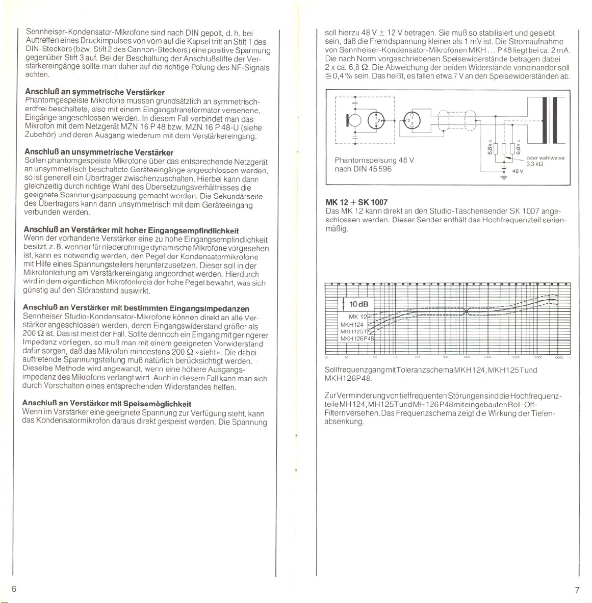
MK 12 + SK 1007
Das MK 12 kann direkt an den Studio- Taschensender SK 1007 ange-
schlossen werden. Dieser Sender enthält das Hochfrequenzteil serien-
mäßig.
al10dB
MKH124
MKH125T
I;MK12'
MKH 126P4
Sollfrequenzgang mitT oleranzschemaM KH 124, MKH 125T und
MKH126P48.
ZurVerm inderu ngvon tieffrequenten Störungen sinddie Hochfrequenz-
teileMH 124, MH 125TundMH 126 P48miteingebauten Roll-Off-
Filternversehen. Das Frequenzschema zeigt die Wirkung der Tiefen-
absenkung.
'
'
a
'"
'"
<D
48V
-
-
--
-
oderwahlweise
3.3kQ
9
-
-
-
[
-
-
6
7
Page 6

MKH 124
Übertragungsbereich
Richtcharakteristik . .
Feld-Leerlauf-Übertragungsfaktor
bei 1000Hz.
ElektrischeImpedanzbell 000 Hz
Minimale Abschlußimpedanz.
Geräuschspannungsabstandnach
DIN45590
Spalsespannung
Speisestrom
Arbeitstemperatur-Bereich
Steckerund Steckerbeschaltung
Mikrofonteil
HF-Teil
Anschlußkupplung
Mikrofon~ HF-Teil
HF- Teil ~ Verstärker
Abmessungeninmm
Mikrofonterl MK 12
HF-Teil
Mikrofongewicht
Oberfläche MK 12
Änderungen,vorallemzumtechnischenFortschntt,vorbehalten.
40 20000 Hz
Kugel
ca.3,2 mV/Pa
ca. 150 Q
2kQ
. 62dB
. 8V:t 2V
ca.5 mA
-10° C bis + 70' C
1pol. LEMO-HF-Stecker 1pol. LEMO-HF-Stecker
6poliger Stecker T 3402 000 3poiiger Stecker
1,2, 5,~ 0,3 ~ - 8V4~ NF 1~ NF,2~ Gehäuse
Lemo F00250/AG/3 auf
Lemo RC00250/AG/3
6pollge verschraubbare
Kupplung13403000
11,5x36x12
270x43
ca.919
Satinnickei,
mattschwarzund
fernsehgrau
MKH 125T
40 20000 Hz
Kugel
ca.20 mV/Pa
ca.20 Q
200 Q
62 dB
12V:t 2V
ca.6 mA
-10° C bis + 70° C
nach DIN41524
3 ~ NF, nach DIN 45595
Lemo F00250/AG/3 auf
Lemo RA00250
3poligeverschraubbareNorm-
kupplungnachDIN41524,
z.B.T3261001
11,5x36x12
190x140
1O0g
Satinnickel,
mattschwarzund
fernsehgrau
MKH 125 T-U MKH 126 P 48
40 20000 Hz
Kugel
ca.20 mV/Pa
ca.20 Q
200 Q
62 dB
12V:t 2V
ca.6 mA
- 10' C bis + 70' C
1pol. LEMO-HF-Stecker
3pollger Cannon XLR-3
1 ~ Gehause,2 ~ NF
3~ NF
Lemo F 00250/ AG/3 auf
Lemo RA 00250
3pollge Cannon-Kupplung
XLR-3-11 C
11,5x36x12
190x155
11Og
Satmnlckel,
mattschwarzund
fernsehgrau
40 20000 Hz
Kugel
ca.20 mV/Pa
ca.20 Q
600 Q (200 Q bis 30 Pa)
62 dB
48V:t 12V
ca.2 mA
-10° C bis + 70° C
1pol. LEMO-HF-Stecker
3poliger Stecker
nachDIN41524
1~ NF,2~ Gehäuse
3~ NF, nachDIN 45596
Lemo F00250/AG/3 auf Lemo F00250/AG/3 auf
Lemo RA00250 Lemo RA00250
3poiigeverschraubbareNorm- 3poiigeCannon-Kupplung
kuppiungnachDIN41 524 XLR-3-11C
z.B.13261 001
11,5x36x12
190140
1O0g
Satinnickel,
mattschwarz
MKH 126 P 48-U
40 20000 Hz
Kugel
ca. 20 mV/Pa
ca. 20 Q
600 Q (200 Q bis 30 Pa)
62 dB
48 V :t 12 V
ca. 2 mA
-lO°Cbls + 70°C
1pol. LEMO-HF-Stecker
3pollger Cannon XLR-3
1 ~ Gehäuse
2 ~ NF, 3 ~ NF
11,5x36x 12
190x155
110g
Satinnickel,
mattschwarz
KONDENSATOR-MIKROFON-
ZUBEHÖR
Batterieadapter
BatterIeadapter MZA 15
Kann an beliebiger Stelle in das
Mikrofonkabel eingeschaltet
werden. Bestückt mit 9 Queck-
silber-Knopfzellen, Mallory RM
625, ist eine ununterbrochene
Betriebszeit von 50 bis 60 Stun-
den möglich. Die Knopfzellen sind
in allen Verkaufsstellen für Hör-
hilfen erhältlich. Um ein unnötiges
Entladen der Batterien zu ver-
meiden, sollte der Batterieadapter
vom Mikrofon getrennt werden,
wenn er nicht im Gebrauch ist
Abmessungen in mm: 220 x 132.
BatterIeadapter MZA 15-U
Mit Cannon-Kupplung XLR-3-
11 C und -Stecker XLR-3-12 C
ausgerüstet und somit für die
MKH-U-Typen einsetzbar. Be-
stückung wie MZA 15. Besonder-
heit: Beim Zusammenstecken
von Stecker und Kupplung zeigt
eine eingebaute Leuchtdiode den
Batteriezustand an. Um ein un-
nötiges Entladen der Batterien zu
vermeiden, sollte der Batterie-
8
adapter vom Mikrofon getrennt
werden, wenn er nicht in Ge-
brauch ist. .
Abmessungen in mm: 220 x 152.
Netzgeräte
Netzgerät MZN 16 T und T-U.
Für den gleichzeitigen Betrieb
von zwei Mikrofonen. Anschluß an
220 V -- oder 110 V --Netz.
Das Gerät kann an beliebiger
Stelle in der Anschlußleitung ein-
geschaltet werden. Modell T-U mit
Cannon-Armaturen.
Abmessungen in mm:
168 x 120 x 50.
Netzgerät MZN 16 P 48 und
MZN 16 P 48-U
Stromversorgungsgerät für 48 V-
Phantomspeisung nach DIN
45596. Für die Kondensator-
Mikrofone derTypenreihe MKH . ..
P48 ist das Netzgerät MZN 16 P48
bestimmt Das MZN 16 P48-U ist
mit Cannonstecker ausgerüstetfür
die Mikrofone MKH . . . P 48-U
geeignet An beiden Geräten kön-
nen gleichzeitig zwei Mikrofone
angeschlossen werden.
Abmessungen in mm:
168 x 120 x 50.
Zusatzgeräte
Transistor-Verstärker
KAT 15-2
Für den Anschluß von Konden-
sator-Mikrofonen oder symmetri-
schen niederohmigen dynami-
schen Mikrofonen an die line- bzw.
Anschlußkabel
Anschlußkabel KA 1 und KA 7
Dreiadrig abgeschirmtes Kabel.
Mit 3poligem Normstecker nach
DIN 41524.
KA 1: 1,5 m lang, KA 7: 7,5 m lang.
accessory-Eingänge der Nagra 111
oder Nagra IV. Betriebsart wählbar:
T = Tonader (MKH)
N = dynamisch
Abschaltbares Trittschallfilter ein-
gebaut.
Abmessungen in mm:
85 x 40 x 25.
Roll-oft-Filter MZF 15
Anschlußkabel KA 7-1
Für alle Sennheiser-Mikrofone,
deren Typenbezeichnung mit U
endet. Das Kabel hat auf einer
Seite eine Cannon-Kupplung, die
andere Seite ist frei für den jeweils
notwendigen Stecker. Länge des
Kabels: 7,5 m.
Das Roll-oft-Filter MZF 15 soll
zwischen Speisespannungs-
quelle und Verstärkereingang und
nur hier, in das Verbindungskabel
eingeschaltet werden. Tiefen-
absenkung bei 50 Hz ca. 6 dB
und bei 25 Hz ~ 15 dB.
Abmessungen in mm:
22 0 x 152.
Anschlußkabel KAM 1-5
Für den Anschluß an Mikroport-
Sender SK 1007,
SK 1008 und den Reportage-
sender SER 1. Die Mikrofone
werden aus den Sendern ge-
speist. KAM 1-5: 1 m lang.
Weiteres allgemeines Zubehör z. B. Stative, Ausleger, TischfüBe usw.
ist aus unserem Gesamtkatalog »Sennheiser revue« zu entnehmen.
9
Page 7

LAVALIERCONDENSER MICROPHONE
MKH 124, MKH 125 T, MKH 126 P48
Introduction
The microphone part MK 12 is a Lavalier condenser microphone in RF-
technique leaturing a diaphragm 01only 6 mm diameter. Corresponding
to its use the microphone was designed as pressure transducer (omni-
directional). Therelore, the MK 12 is very insensitive to handling noises.
The complete microphone consists 01two parts, the miniature micro-
phone and the electronic unit. MH 124, MH 125 T, MH 126 P 48 or the
studio transmitter SK 1007 may be alternatively connected to the MK 12.
The prolongation between microphone and electronic unit is possible
with connection cable MZV 125.
10
Technical Notes
High Frequency Circuit
The capsule 01 a RF condenser microphone presents, contrary to low
Irequency circuits, a low impedance output. Instead 01the high pola-
rization voltage normally required, a high Irequency capsule needs only a
high Irequency voltage 01about 10 volts, which is produced by a built-in
~
low noise oscillator (8 MHz). The low capsule impedance leads to a high
performance reliability 01the microphones.
MK12 + MH 124= MKH124
The MKH 124 is designed lor direct connection to the Microport-
transmitter SK 1008-3. The power supply is provided by the transmitter.
MK 12 + MH 125 T = MKH 125 T
The MKH 125 T is designed lor AB-powering.
Senn heiser electronic introduced A-B powering, which was then
standardised in DIN 45595. As with dynamic microphones, only two wires
are required to connect the microphone when this powering system is
being used. The operating current is led along the same wires as the
audio Irequency signal, so that the circuitry in the microphone does not
have to be connected to ground. Because 01these ground-Iree tech-
niques the highest possible values 01immunity lrom noise er disturbance
are achieved.
11
Page 8

The connection 01Senn heiser condenser microphones and dynamic
microphones as weil is carried out using the principle 01voltage matching.
The advantages 01this system are that neither impedance variations 01the
microphone output nor 01the amplilier input exercise a noticeable
influence on the total Irequency response. The source impedance 01the
Sennheisercondenser microphone with A-B powering is so low (approx.
20 Q at 1000 Hz) that an amplilier input with an impedance 01at least
200 Q will be suitable.
Sennheiser condenser microphones produce relatively large output
voltages, these can be up to 1 volt with maximum sound pressure levels.
This has the advantage that even with long cables induced interference
signals can be disregarded. Also the internal noise produced by the
microphone does not contribute to the total noise level. The microphones
are litted with high Irequency lilters, which ensure that no high Irequency
signals lrom the microphone can affect the external circuitry, and also that
the microphone itsell is protected Irom high Irequency disturbance. It is,
therelore, notnecessary, even underthe most difficult conditions, totake
special precautions such as double screening 01the cables or the
provision 01 high Irequency Iilters.
Sennheiser condenser microphones are polarised according to DIN
standard i. e. when apressure signal strikes the capsule lrom the Iront,
Pin 1 01the DIN-connector (resp. pin 2 01the Gannon connector) goes
positive with relerence to Pin 3. This should be considered when the
amplilier input is being wired.
Connection to Amplifiers with balanced Inputs
In this case the microphone is simply connected to the input 01an
amplilier via a battery adapter MZA 15 or the power supply MZN 16 T.
Connection to Amplifiers with unbalanced Inputs
In many cases, lor example most tape recorders, the input socket is
unbalanced. In this case one side olthe b~lanced microphone output has
to be earthed. Apart lrom cases where the microphone is being used lor
prolessional studio purposes, this is not critical, asthe large output voltage
01the microphone combined with its low output impedance provides a
large signal to noise ratio. Gare should be taken, however, that no multiple
ground circuits are lormed when the microphones are mounted on
tripods etc.
Connection to Amplifiers with High Input Sensitivity
Inthe amplilier being used has a very high input sensitivity, i. e. when it is
normally intended lor use with dynamic microphones, it can be necessary
to reduce the output voltage Irom the microphone by means 01a voltage
divider. This should be built into the microphone cable atthe amplilier
input. By this means the large signal on the microphone cable is
maintained up to just belore the amplilier, which helps to increase the
signal to noise ratio.
Connection to Amplifiers with Defined Input Impedances
Sennheiser studio condenser microphones can be connected directly
to all ampliliers whose input impedance is larger than 200 Q. This is usual
in the majority 01cases. However, il the input impedance is smaller than
200 Q, a resistor 01appropriate value should be placed in series with the
microphone so that it "sees" at least 200 Q. The voltage division caused
by this series resistor must 01course be considered.
The same method can be used when a higher output impedance 01the
microphone is demanded. In this case again aseries resistor can be used
to provide correct matching.
Connection to Amplifiers with Powering Facilities
1Ianappropriate voltage source is available in the amplilier the condenser
microphone can be powered directly. The voltage should be
12.volts :t 2 volts. It should be so stabilised and liltered, that the un-
12
weighted noise voltage is less than 5 f.lVand that the weighted noise
components are less than 2 f.lV.The current consumption 01the
microphone is approximately 6 mA. According to the DIN standard the
leed resistors should be 2 x 180 Q. This means that approx. 2 volts are
lost across the resistors. .
,n-Tnnnn,
I I
I I
I I
I I
I
I I
I I
I I
I
'_n- nnnn_'
T
A-BpoweringaccordingtoDIN45595
,_nTn_nn_,
I I
I I
I I
I I
I I
I I
I I
I I
:_n_L___n_nl
,mrm :
I I
I I
i : -
I I
I I
I I
:n__L n__1
I
I
(':n-7-"'.
I I I I
" I I
, . ~---, /b
I
180Q
12V
,::,:.,<.n_"1) b
W
+
" S
360Q +12V
A-B powering unbalanced connection
MK 12 + MH 126 P48 = MKH 126 P48
The MKH 126 P 48 is designed lor phantom powering. All Sennheiser
microphones designated MKH . . . P 48 and P48-U are 48 V phantom-
powered according to DIN 45596. Either condenser- or dynamic micro-
phones Irom Senn heiser electronic employ the principle 01voltage
matching. This "no load condition" has the advantage that neither
impedance variations 01the microphone output nor 01the amplilier input
have a noticeable inlluence on the total performance 01the system
(e. g. Irequency response). The source impedance 01Senn heiser con-
denser microphones with phantom powering is extremely low (about
20 Q at 1000 Hz) so that the amplilier input impedance has only to be
at least 200 Q.
Senn heiser condenser microphones produce relatively large output
voltages exceeding 1 volt at maximum sound pressure levels. This has
the advantage that even with long cables induced interference signals can
be disregarded. Also the internal noise produced by the microphone does
\
not contribute to the total noise level. The microphones are litted with
RF lilters which ensure that no high Irequency signals lrom the micro-
I
phone can affect the external circuitry and that the microphone itsell is
protected Irom high Irequency disturbance. It is therelore not necessary,
even under the most difficult conditions, to take special precautions, such
as double screening 01the cables or the provision 01high Irequency lilters.
Senn heiser condenser microphones are polarised according to DIN
stahdard i. e. when apressure pulse strikes the capsule lrom the Iront,
Pin 1 01the DIN-connector (resp. pin 2 01the Gannon connector) goes
positive with relerence to Pin 3. This should be considered when the
amplilier input plug is being wired lor correct phasing.
Connection to Amplifiers with balanced Inputs
Phantom-powered microphones are generally to be connected to
balanced ground-Iree translarmer inputs.
,n-
!-~-I
===l~i
180Q 'nn' L_-
II
NF
+,c-
-12V
NF
i+
13
Page 9

Inthis case the microphone is simply connected via the power supply
MZN 16 P48 resp. MZN 16 P 48-U (see accessories) to the inputs ofthe
amplifier.
Connection to Amplifiers with unbalanced Inputs
In many cases, for example most home-tape recorders, the input socket
is unbalanced. If a phantom-powered microphone is to be connected to
such inputs it is generally necessary to use a transformer. The secondary
of this audio-transformer may then be connected - one side grounded-
to the input. Proper voltage matching is achieved by selecting a suitable
transformer ratio.
Connection to Amplifiers with High Input Sensitivity
Ifthe amplifier being used has a very high input sensitivity i. e. when it is
normally intended for use with dynamic microphones, it can be necessary
to reduce the output voltage from the microphone by means of a voltage
divider. This should be built into the microphone cable at the amplifier
input. This waythe large signal on the microphone cable is maintained up
to just before the amplifier, which helps to increase the signal to noise ratio.
denser microphones MKH . . . P48 is appx. 2 mA. According to the DIN
standard the feed resistors should be 2 x appx. 6.8 kQ. The difference
between the two resistors should be ~ 0.4 %. This means that approx.
7 volts are lost across the resistors.
i---r i
I I
I I
I I
I
I
I I
I I
I I
~---I J
,
J
Phantom-powering 48 V
according to DIN 45596
"
'"
ro
<6
MK 12 + SK 1007
The MK 12 can be connected directly to the studio pocket transmitter
SK 1007. This transmitter already contains the electronic part.
48V
alternatively
3.3kQ
[
Connection to Amplifiers with Defined Input Impedances
Sennheiser studio condenser microphones can be connected directly to
all amplifiers whose input impedance is larger than 200 Q. This is usual
inthe majority of cases. Should - however - the input impedance be
smaller than 200 Q, a resistor of appropriate value should be placed in
series with the microphone so that it "sees" at least 200 Q. The voltage
division caused by this series resistor must, of course, be considered.
The same method can be used when a higher output impedance of the
microphone isdemanded. In this case again, aseries resistor can be used
to provide correct matching.
Connection to Amplifiers with Powering Facilities
If an appropriate voltage source is available in the amplifierthe condenser
microphone can be powered directly. The voltage should be
48 volts:!: 12 volts. It should be stabilised and filtered, thatthe unweighted
noise voltage is less than 1 mV. The current taken by Sennheiser con-
MKH124
Frequency response. .
Direclional characlerislic . . . .
Open circuil oulpul vollage al 1000 Hz
Source impedance al 1000 Hz
Minimalload impedance ...
Oulpul level re. 1 mW/10 dynes/cm2
S/N ralio (DIN 45 590)
Operating voltage
Currenldrawn .
Temperature range
Connections
Microphone
HF-section
Connectors
Microphone ~ HF seclion
HFsection~ Amplilier
Dimensions in mm
Microphone MK12
HFseclion . .
Weighlol microphone
Finish MK12
WereserveIhe righl to aller specilicalions, in particularwith regard10lechnicalimprovements.
40...20000 Hz
omnidireclional
appx. 3.2 mV/Pa
appx. 150 Q
2kQ
-53.5dB
62 dB
8V:t 2V
appx. 5 mA
-10'Clo + 70'C
1-pin LEMO-RF-plug
6-pin plug T3402 000
1,2, 5,~ 0.3~-8 V
4 ~ signal
Lemo F 00250/ AG/3 10
Lemo RC 00250/ AG/3
Tuchel T3403 000
11.5 x 36 x 12
27 0 x 43
appx. 91 9
satin nickel,
dull black and TV-grey
MKH125 T
40. .20000 Hz
omnidirectional
appx. 20 mV/Pa
appx. 20 Q
200 Q
-27.8dB
62dB
12V:t 2V
appx. 6 mA
-10' C 10+ 70' C
1-pin LEMO RF-plug
3-pin plug 10 DIN41524
1~ signal
2 ~ case, 3 ~ signal
to DIN 45595
Lemo F 00250/ AG/3 to
Lemo RA 00250
DIN3-pin i. e. T3261 001
11.5 x 36 x 12
190x 140
1009
satinnickel,
duI1blackandTV-grey
- -
f=
T10dB
f=
MK12
E
MKH124
r=
f=
MKH125T
MKH 125P48
t=
Standard frequency responsewith tolerance limits MKH 124, MKH 125 T
and MKH 126 P48.
-
-
- -
-- -
- -. -
--
-
-
-
To reduce low frequency interferences, electronic units MH 124,
MH 125 T and MH 126 P 48 are equipped with a built-in roll-off filter.
The frequency chart shows the corresponding response.
MKH 125 T-U MKH 126 P 48 MKH 126 P 48-U
40. .20000 Hz
omnidireclional
appx.20 mV/Pa
appx.20 Q
200 Q
-27.8dB
52 dB
12V:t 2V
appx.6 mA
-10'Clo + 70'C
1-pin LEMO RF-plug
Cannon 3-pin XLR-3
1 ~ case
2~ case,3~ signal
Lemo F 00250/ AG/3 10
Lemo RA 00250
XLR-3-11 C
11.5 x 36 x 12
190x155
110 9
salmnickel,
dull black andTV-grey
40. .20000 Hz
omnidireclional
appx.20 mV/Pa
appx.20 Q
600Q(200Q up1030 Pa)
-32dB
62 dB
48V:t 12V
appx.2 mA
-10'Clo + 70'C
1-pm LEMO RF-plug
3-pin plug 10 DIN 41 524
1~ signal,2~ case,
3~ signal 10 DIN 45 596
Lemo F 00250/ AG/3 10
Lemo RA 00250
DIN 3-pin i.e. T 3261001
11.5 x 36 x 12
190140
100 9
salin nickel,
dull black
40. .20000 Hz
omnidtreclional
appx.20 mV/Pa
appx.20 Q
600 Q (200 Q up 1030 Pa)
-32dB
62 dB
48V:t 12V
appx.2 mA
-lO'Clo + 70'C
l-pin LEMO RF-plug
Cannon3-pin XLR-3
1~ case,2~ signal,
3~ signal
Lemo F 00250/ AG/3 10
Lemo RA 00250
XLR-3-11 C
11.5 x 36 x 12
190x 155
1109
salin nickel.
dullblack
14
15
Page 10

CONDENSERMICROPHONE
ACCESSORIES
MICROPHONE-CRAVATE
APINCE
MKH124,MKH125T,MKH126 P48
Batteryadapters
Battery adapter MZA 15
Can be connected into the micro-
phone line at any point. Fitted with
9 mercury cells Mallory RM 625, it
provides a continuous operation
for 50 to 60 hours. The mercury
cells can be purchased inall shops
with cater for the hard of hearing.
To prevent an unnecessary dis-
charge of the batteries, the battery
adapter should be unscrewed
from the microphone when it is not
in use.
Dimensions in mm: 220 x 132.
Battery adapter MZA 15-U
Fitted with Cannon connector
XLR-3-11 C and plug XLR-3-12 C
for use with the MKH-U types.
Batteries as in MZA 15.
Special feature: If the plug and
connector are connected to-
gether the battery condition is
indicated by~ built-in signal diode.
T0 prevent an unnecessary dis-
charge of the batteries the battery
adapter should be unscrewed
from the microphone when it is not
in use.
Dimensions in mm: 220 x 152.
Power supplies
Power unit MZN 16 T and T-U
For simultaneous powering of two
microphones. Connection to
220 volt or 110 volt supplies. The
unit can be included in the micro-
phone cable at any point. Model
T-U with Cannon connectors.
Dimensions in mm:
168x120x50.
AC Power Supply MZN 16 P 48
and MZN 16 P 48-U
The power supply is designed for
48 Vphantom powering, according
to engineering standard
45596. ModelMZN16 P48is
used with condenser microphones
of the MKH . . . P 48 type, while
model MZN 16 P48-U isequipped
with XLR connector for condenser
microphones of the
Further general aceessories e. g. tripods, booms, table stands etc. can
be found in our catalogue "Sennheiser-revue".
DIN
MKH ... P48-U type. Both models
will supply power to two micro-
phones simultaneously.
Dimensions in mm:
168 x 120 x 50.
Auxiliary units
Transistor amplifier KAT 15-2
For the connection of condenser
microphones, or symmetricallow
impedance dynamic micro-
phones, to the line and accessory
inputs respectively, ofthe Nagra 111
or Nagra IV. Selected functions:
T = condenser microphones
N = dynamic microphones
A switchable footlall filter is in-
cluded.
Dimensions in mm: 85 x 40 x 25.
Roll-off-filter MZF 15
The roll-olf-filter MZF 15 should
be included only between supply
voltage source and amplifier input.
Frequency reduction
at 50 Hz approx. 6 dB
at 25Hz;S; 15dB
Dimensions in mm: 22 0 x 152.
Cables
Connecting cable KA 1and KA 7
Tripie eonductor sereened cable.
Fitted with 3 pin conneetors
aeeording to DIN 41524.
KA 1: 1.5 m long, KA 7: 7.5 m long.
Connecting cable KA 7-1
For use with all Sennheiser micro-
phones with the sulfix U. The
KA 7-1 is fitted on one end with a
cannon female connector, the
other end is free for the connection
of the necessary plug. The cable
is 7.5 meters long.
Connecting cable KAM 1-5
For the connection of series 6
microphones to the "Mikroport"
transmitters SK 1007,
SK 1008 and the SER 1. The
microphones are powered from
the transmitter.
KAM 1-5: 1 m long.
16
Introduction
L'element micro MK 12 est un micro-cravate a pince electrostatique HF,
avec un diaphragme de 6 mm de diametre. Conformement a son utili-
sation,le micro est un capteur de pression, a directivite omnidirectionnelle
et pour cette raison insensible aux bruits d'origine mecanique. Le micro
complet est compose de deux elements: un element micro et un element
haute-frequence. L'element micro MK 12 est le meme pour le MH 124,
MH 125 T, MH 126 P 48 ou I'emetteur de studio SK 1007. Un cordon
prolongateur MZV 125 entre I'element micro et I'element HF est
disponible en accessoires.
Notices techniques
Montage haute-frequence
Contrairement au montage basse frequenee, la eapsule d'un miere
electrostatique a haute frequence presente une faible impedance. A la
piace de latension de polarisation relativementeJevee, la capsule n'est
sou mise qu'a une faible tension d'environ 10 volts, fournie par un oseilla-
teur (8 MHz) a faible bruit de fond. Lafaible irnpedanee du systeme apour
eonsequenee un bruit de fond tres faible et une haute fiabilite
des mierophones.
Types
MK12 + MH 124= MKH 124
Le MKH 124 est prevu pour le raceordement direet a I'emetteur Mieroport
SK 1008-3. L'alimentation est assuree par I'emetteur.
MK12 + MH 125T = MKH 125T
Le MKH 125 Test prevu pour le raecordement ades cäbles alimentes par
eonducteurs de modulation. C'est Senn heiser qui a introduit I'alimenta-
17
Page 11

tion atravers les conducteurs de modulation. Ce procede a ete normalise
par OIN 54595.
Comme pour les microphones dynamiques, cette technique n'exige que
deux conducteurs. Le chemin du courant d'alimentation est identique a
celuLde la tension audiofrequence (AF), ce qui permet d'eviter que les
circuits du micro soient galvaniquement connectes a la masse. Cette
technique «sans mise a la masse» garantit une excellente protection
anti-parasites.
Pour le branchement de ses microphones electrostatiques, Senn heiser
utilise, comme pour les microphones dynamiques, le principe de
I'adaptation en tension. Oe ce fait, ni les variations d'impedance du micro-
phone, ni celles de I'amplificateur n'ont d'influence sensible sur lacourbe
de reponse. L'impedance de source des microphones electrostatiques
Sennheiser est tellement faible (environ 20 Q a 1000 Hz) que la seule
exigence a I'amplificateur est que son impedance soit au moins 200 Q.
Les micros electrostatiques Sennheiser donnent des tensions de sortie
relativement elevees, pour des pressions acoustiques maximales
presque 1 V. L'avantage en est que, meme pour des cables.longs, les
tensions parasitaires n'ont aucune influence. Enoutre, I'influence du bruit
de fond de I'amplificateur du micro est pratiquement inexistante. Oe plus,
tous ces micros Sennheiser sont equipes de filtres haute-frequence
dimensionnes genereusement. Ces filtres eliminent les tensions para-
sites HF de la ligne et protegent les microphones contre des champs HF
exterieurs. Meme pour des conditions difficiles de transmission, iI n'est
pas necessaire de prevoir de protections speciales (double blindage de
lignes, materiel anti-HF, etc.). La polarite des micros est conforme aux
normes OIN c. a. d. si une impulsion de pression touche la capsule de
front, labroche 1de la fiche OIN (resp. broche 2de lafiche Cannon) pos-
sede une tension positive par rapport a la broche 3. Lors du cablage des
broches de I'amplificateur veillez donc a la polarite correcte du signal BF.
Branchement ades amplificateurs symetriques
Oans ce cas on relie le micro a I'entree de I'amplificateur par I'inter-
mediaire de I'alimentation secteur MZN 16 T ou d'un adaptateur a piles
MZA 15.
Branchement ades amplificateurs asymetriqu'es
Tres souventon ne dispose que d'amplificateurs aentree asymetrique
p. ex. pour beaucoup de magnetophones HiFi. Oans ce cas on met tO,ut
simplement a la masse une des broches de la sortie BF. En dehors des
studios, cette solution est peu critique. Le niveau eleve en combinaison
avec I'impedance interne faible du micro electrostatique garantissent un
rapport signal/bruit suffisant. Veillez cependant a ne pas faire de mises a
laterre multiples lors de I'utilisation de pieds de micro.
Branchement ades amplificateurs a haute sensibilite
Si I'amplificateur present possede une sensibilite trop eleve, (p. ex. si
I'amplificateur est prevu pourdes micros dynamiques abasse impedance)
il est parfois necessaire de diminuer latension du micro a I'aide d'un
diviseur de tension. Celui-ci doit etre incorpore au cable du micro a
I'entree de I'amplificateur. Par ces moyens, le niveau eleve est maintenu
jusqu'a I'entree de I'amplificateur, ce qui est propice au rapport
signal/bruit.
Branchement ades amplificateurs a impedance basse
Les rnicros electrostatiques pour studios de Senn heiser peuvent etre
branches directement a tous les amplificateurs ayant une irnpedance
superieure a 200 Q, ce qui est normalernent le cas. Toutefois, si I'impe-
dance d'entree de I'amplificateur est inferieure, il faut choisir une
resistance additionnelle convenant pourque le micro «voie» au moins
200 Q. La division de tension qui s'ensuit doit evidemrnent etre prise en
consideration. La meme methode est employee si on a besoin d'une
impedance micro plus elevee. Oans ce cas aussi une resistance
additionnelle mene a une adaptation correcte.
18
Branchement ades amplificateurs av~c possibilites d'alimentation
SiI'amplificateur possede une tension convenant, lemicro electrostatique
peut en etre alimente directement. La tension devrait etre de 12 V :t 2 V.
Elle doit etre stabilisee et filtree de teile maniere que latension non
ponderee soit inferieure
2 !-IV.Le courant d'alimentation des micros electrostatiques MKH de
Sennheiser se situe a environ 6 mA, la valeur des resistances d'alimen-
tation standardisees est de 2 x 180 Q. Par consequent, les deux
resistances subissent une chute de potentiel de 2 V.
,---T
, ,
, ,
, ,
, ,
, ,
, ,
, ,
, ,
: L '
Alimentation par conducteurs
de modulation seion OIN 45595
a5 !-IVet que latension ponderee inferieure a
,
r~tII
1800 , , c_-1800
12VOS
+12V
bO,
:---r ,
, '
, '
, '
, '
, ,
, ,
, ,
: L :
Alimentation par conducteurs de modulation.
Branchement asyrnetrique
MK 12 + MH 126 P48 = MKH 126 P48
Le MKH 126 P48 est prevu pour le raccordement ades cables a alimen-
tation fantöme. Tous les micros electrostatiques de Sennheiser electronic
avec la designation MKH . . . P 48 ou P48-U sont a alimentation fantöme
48 V selon 01N45596. Les deux conducteurs de modulation sont donc a
tension d'alimentation positive. Le courant de retour passe par le
blindage.
Pour le branchement de ses microphones electrostatiques, Senn heiser
utilise, comme pour les microphones dynamiques, le principe de
I'adaptation en tension. Cela signifie que I'impedance d'entree de
I'amplificateur est beaucoup plus elevee que celle du micro de teile sorte
que celui-ci marche presque a video Oe ce fait, ni les variations d'impe-
dance du microphone, ni celles de I'amplificateur n'ont d'influence
sensible sur la courbe de reponse. L'impedance de source des micro-
phones electrostatiques Senn heiser aalimentation fantöme est.tres
faible, environ 20 Q a1000 Hz. Laseule exigence posee a I'amplificateur
est d'avoir une impedance d'entree d'au moins 200 Q.
Les micros electrostatiques Sennheiser donnent des tensions de sortie
relativement elevees, pour des pressions acoustiques maximales,
presque 1 V. L'avantage en est que, meme pour des cables longs, les
'tensions parasitaires n'ont aucune influence. En outre, I'influence du bruit
de fond de I'amplificateur du micro est pratiquement inexistante. Oe plus,
tous ces micros Sennheiser sont equipes de filtres haute-frequence
dimensionnes genereusement. Ces filtres eliminent les tensions para-
sites HF de la ligne et protegent les microphones contre des champs HF
exterieurs. Meme pour des conditions difficiles de transmission, il n'est
pas necessaire de prevoir de protections speciales (double blindage de
ED
i"~---7"\ a 360Q
, , , ,
, , , ,
\".' '.1) b
c::::J
c.=:J
NF
+' f:=-
-12V
NF
f:t
19
Page 12

lignes, materie Ianti-HF, etc.). La polarite des micros Senn heiser est con-
forme a la norme DIN, c. a. d. si une impulsion de pression touche la
capsule de front, la broche 1 du connecteur DIN (resp. broche 2 du con-
necteur Cannon) possede une tension positive par rapport a la broche 3.
Lo'rsdu cablage des broches de I'amplificateur, veillez donc a la polarite
correcte du signal BF.
Branchement ades amplificateurs symetriques
Enprincipe,les micros aalimentation fantöme doivent etre branchesades
entrees symetriques sans mise alaterre, c. a. d. ades entrees atransfor-
mateur d'entree.
Dans ce eas on relie le micro a I'alimentation secteur MZN 16 P48 resp.
MZN 16 P 48-U (voir accessoires) et la sortie du MZN a I'entree de
I'amplificateur.
Branchement ades amplificateurs asymetriques
Si des micros aalimentation fantöme doivent etre branches a des entrees
asymetriques, en passant par I'alimentation seeteur appropriee, un trans-
formateur doit etre intercale. En choisissant correctement le rapport de
transformation, on arrive a I'adaptation en tension adequate. Le cöte
secondairedutransformateurpeutalorsetre branche ae far;;onasymetrique
a I'entree de I'amplificateur.
Branchement ades amplificateurs a haute sensibilite
Si I'amplificateur en presence possede une sensibilite trop elevee (p. ex.
amplificateur pour micros dynamiques a basse impedance) il est parfois
necessaire de diminuer latension du miere a I'aide d'un diviseur de ten-
sion. Celui-ci doit etre incorpore au cable du micro a I'entree de I'amplifi-
cateur. Le niveau elevee est ainsi maintenu jusqu'a I'entree de I'amplifi-
cateur, ce qui est propice au rapport signal/bruit.
Branchement ades amplificateurs a impedance definie
Les mieros electrostatiques de studio Senn heiser peuvent etre branches
directement atous les amplificateurs qui ont une impedance superieure
a 200 Q, ce qui est souvent le cas. Si toutefois, votre amplificateur pre-
sente une impedance inferieure, ilfaut choisir une resistanee additionnelle
convenant pourque le micro «voie» au moins 200 Q. La division de ten-
sion qui en resulte doit evidemment etre prise en consideration.
La meme methode est employee si on a besoin d'une impedance miero
plus elevee. Dans ce cas aussi, une resistance additionnelle meme a une
adaptation correcte.
Branchement ades amplificateurs avec possibilites d'alimentation
Si I'amplificateur possede une tension convenant, le microphone electro-
statique peut en etre alimente directement. La valeur de latension doit
etre de 48 V :t 12 V. Elle doit etre stabilisee etfiltree de teile maniere que
la tension non-ponderee soit inferieure a 1 mV. Le courant de consom-
mation pour les micros electrostatiques Senn heiser MKH . . . P 48 'est
d'environ 2 mA. La valeur des resistances standardisees d'alimentation
est de 2 x 6,8 kQ, la variation d'une resistance par rapport a I'autre
~ 0,4 %. La chute de potentiel aux deux resistances est d'environ 7 V.
i---rn---n~
I L---, I
:.A ~:
I
:'
I I
~
I I
'-n-Inm _n~
Alimentation fantöme 48 V
selon DIN 45596
MK 12 + SK 1007
Le MK 12 peut EHrebranche directement a I'emetleur de studio SK 1007.
Cet emetteur est deja equipe de la partie HF, depart usine.
t10dB
MK12
=
==
MKH124
==
MKH125T
==
MKH 126P4
Courbe de reponse de consigne avectolerances, MKH 124, MKH 125 T,
MKH 126 P 48.
Afin de reduire les interferences a basse frequence, les parties HF
MH 124, MH 125 T et MH 126 P 48 ont ete pourvues de filtres roll-off. La
courbe de reponse montre I'influence de I'attenuation des graves.
'
"
0
'"
'"
"'
"'
<D
<D
~3.3 kQ
48 V
- -
-
-
-
- --
--
-
[
ou alternative ment
-
-
-
-
20
21
Page 13

MKH124
Bande passante 40. . . 20000 Hz
Directivite . . omnidirectionnelle
Facteur de transmission a vlde a 1000 Hz env. 3,2 mV/Pa
Impedance a 1000 Hz env. 150 Q
Impedance min. de charge .. 2 kQ
Rapport signal/bruit selon DIN45 590 62 dB
Tension d'alimentation 8 V:+:2 V
Consommation . . . . env. 5 mA
Temperatures de fonctionnement - 10' Ca + 70' C
Connecteurs et branchement des
connecteurs
Partie microphone
Partie HF
Connecteurs de raccordement
Microphone~ partieHF
Partie HF~ Amplificateur
Dimensions en mm
Partie microphone MK12
Partie HF.
Poids du mlcrophone
Surtace MK12
Modificatlons, surtout dans I'interet du progres technique, reservees.
fiche HF LEMOunipolaire fiche HF LEMO unipolaire
fiche hexapolalre T 3402 000 fiche tripolaire DIN41 524
1, 2, 5~0, 3~-8 V, 1~ BF,2~ boitier,
4 ~ BF 3 ~ BF, selon DIN45595
Lemo F 00250/ AG/3 sur
Lemo RC 00250/ AG/3
. Tuchel T3403 000,
hexapoiaire vissant
11,5 x 36 x 12
270 x 43
env. 91 g
. nickelee satinee,
noire mate, grise television
ACCESSOIRESPOURMICROS
ELECTROSTATIQUES
MKH125T
40 20000 Hz
omnidirectionnelle
env. 20 mV/Pa
env. 20 Q
200 Q
62 dB
12V:+: 2V
env. 6 mA
-10'Ca + 70'C
Lemo F 00250/ AG/3 sur
Lemo RA 00250
trlpolaire vissant normallse
selon DIN41524, 1
p. ex. T 3261001 '
11,5x36x 12 1
190x140
100 g
nickelee satlnee,
noire mate, gnse television I
MKH125T-U
40 . . .20000 Hz
omnidlrectionnelle
env.20 mV/Pa
env.20 Q
200Q
62dB
12V:+:2V
env.6 mA
-10' Ca + 70° C
fiche HF LEMO unipolaire fiche HF LEMO unipolalre
fiche tripolaire Cannon XLR-3 fiche tripolaire DIN 41 524
1~ boitier,2~ BF, 1~ BF,2~ boHier,
3
~ BF 3~ BF.selonDIN45596
Lemo F00250/AG/3 sur
Lemo RA00250
Cannontripolaire
XLR-3-11 C
11,5x36 x 12
1
190x 155
110g
nickeleesatinee,
nOlremate,grise television
MKH 126 P 48
40. .20000 Hz
omnidirectionnelle
env. 20 mV/Pa
env.20 Q
600 Q (200 Q iusqu'a 30 Pa)
62 dB
48V:+:12V
env.2 mA
-10'Ca + 70'C
Lemo F00250/AG/3 sur LemoF00250/AG/3 sur
Lemo RA00250 Lemo RA00250
tripolairevissable selon tripolalreCannon
DIN41524, p. ex. T 3261 001 XLR-3-11 C
11,5 x36 x 12 11,5x 36x 12
190140 190x155
100g 110g
nickeleesatinee,noire mate nickelee satinee, noire mate
MKH 126 P48-U
--
40...20000 Hz
omnidirectionnelle
env.20 mV/Pa
env. 20 Q
600 Q (200 Q jusqu'a 30 Pa)
62dB
48V:+: 12V
env.2 mA
-10'Ca+70'C
fiche HF LEMO unipolaire
tripolaire Cannon XLR-3
1~ boHier,2~ BF,
3~BF
Adaptateurs a piles
Adaptateurs a piles MZA 15
Cette alimentation a piles s'inter-
cale en n'importe quel point du
cordon du micro. Elle est equipee
de 9 piles-boutons a mercure
(Mallory RM 625). Fonctionne-
ment en regime continu: 50 a 60
heures. Les piles-boutons sont
disponibles dans tous les points
de vente de materiel pour malen-
tendants. Pour eviter une de-
charge superflue des piles, le
MZA 15 devrait etre separe du
micro quand celui-ci est hors
service.
Dimensions en mm: 220 x 132.
Adaptateur a piles MZA 15-U
Avec connecteur Cannon XLR-3-
11 C et fiche XLR-3-12 C pour les
micros MKH-U. Pilescomme pour
le MZA 15.
Particularite: En couplant I'alimen-
tation, une diode lumineuse in-
dique I'etat des piles. Pour eviter
une decharge superflue des piles,
le MZA 15 devrait etre separe du
microquand celui-ci est hors
service.
Dimensions en mm: 220 x 152.
22
Alimentations secteur
Alimentation secteur MZN 16 T
etT-U
Pour I'alimentation simultanee de
deux microphones. Branchement
ausecteur220V~ ou 110V ~.
Le bloc d'alimentation peut etre
intercale en n'importe quel point
du cordon du micro. Modele T-U
avec connecteurs Cannon.
Dimensions en mm:
168 x 120 x 50.
Alimentation secteur
MZN 16 P 48 et MZN 16 P 48-U
Alimentation secteur pour alimen-
tation fantome 48 V selon DIN
45596. Pour les micros electro-
statiques MKH . . . P48 ilYa a
disposition I'alimentation secteur
MZN 16 P 48. Le MZN 16 P 48-U
est equipe de fiches Cannon pour
les micros MKH . . . P 48-U. Les
deux alimentations peuvent
alimenter simultanement deux
micros.
Dimensions en mm:
168x120x50.
Accessoires
supplementaires
Amplificateur atransistors
KAT 15-2
Pour le branchement des micros
electrostatiques ou dynamiques
a impedance basse aux entrees
line resp. accessory des magne-
tophones Nagra 111ou Nagra IV.
Commutateur:
T = microphones electro-
statiques (MKH)
N = microphones dyna-
Filtre atlenuateur des bruits de
pas commutable, incorpore.
Dimensions en mm: 85 x 40 x 25.
Filtre Roll-off MZF 15
Le filtre Roll-off MZF 15 est inter-
cale uniquement entre la tension
d'alimentation et I'entree de I'am-
plificateur. Atlenuation des
frequences: a 50 Hz approx. 6 dB
Dimensions en mm: 220 x 152.
miques.
et a 25 Hz i;:; 15 dB.
Cordons
de raccordement
Cordon de raccordement KA 7-1
Pour tous les micros Senn heiser
dont ladenomination se termine
par la lettre U. Le cordon est
equipe d'un cote d'un connecteur
Cannon, le cote oppose restant
libre poury mettre lafiche requise.
Longueur du cable: 7,5 m.
Cordon de raccordement
KA 1 et KA 7
Cable blinde atrois conducteurs.
Avec fiche tripolaire normalisee
selon DIN 41524.
Longueurs: KA 1: 1,5 m.
Cordon de raccordement
KAM 1-5
Pour le branchement aux emet-
teurs Microport SK 1007,
SK 1008 et a I'emetteur de
reportage SER 1. L'alimentation
des microphones est assuree par
les emetteurs.
Longueur du KAM 1-5: 1 m.
KA 7: 7,5 m.
D'autres accessoires generaux comme p. ex. pieds de micro, perches,
pieds de table se trouvent dans notre catalogue "Sennheiser-revue».
23
Page 14

 Loading...