

Page 1

H:I~I:I H N N:I~::Qj:::
6unllalues6unualpas
apln~ sJaSn
IOldw3,P apolf\I
-_O~~H)l1I\I
~-o~~H)l1I\I
"
.
Page 2
SPEZIAL-MIKROFONE
MKH110 UNDMKH110-1
TECHNISCHE HINWEISE
Hochfrequenzschaltung
Die Kapsel eines Kondensator-Mikrofons in Hochfrequenzschaltung
stellt im Gegensatz zu der in Niederfrequenzschaltung eine niederohmige
Impedanz dar. An der Kapsel liegt anstelle der sonst nötigen hohen Pola-
risationsspannung lediglich eine Hochfrequenzspannung von etwa 10 V,
die durch einen rauscharmen Oszillator (8 MHz) erzeugt wird. Die
niedrige Kapselimpedanz führt zu einer hohen Betriebssicherheit der
Mikrofone.
Kurzbeschreibung
Beide Typen sind Druckempfänger für Sonderanwendungen und Meß-
zwecke. Sie basieren darauf, daß es nur das Prinzip von Kondensator-
Mikrofonen in Hochfrequenzschaltung ermöglicht, einen Frequenz-
umfang bis herunter zu fast 0 Hz zu erfassen.
Allgemeine Daten
Ausführung
Stecker
Beschalfung
Anschlußkupplung
Abmessungen
Gewicht
Technische Daten
, Obertragungsbereich
AkustischeArbeitsweise
Richtcharakteristik
Feld-Leerlauf-Obertra-
. gungstaktorbei 1000Hz
ElektrischeImpedanzbei
, 1000 Hz
MinimaleAbschlußimpedanz
Geräuschspannungsabstand
nachDIN 45 590
Aussteuerungsgrenze
Speisung
Speisespannung
Speisestrom
Temperafurbereich
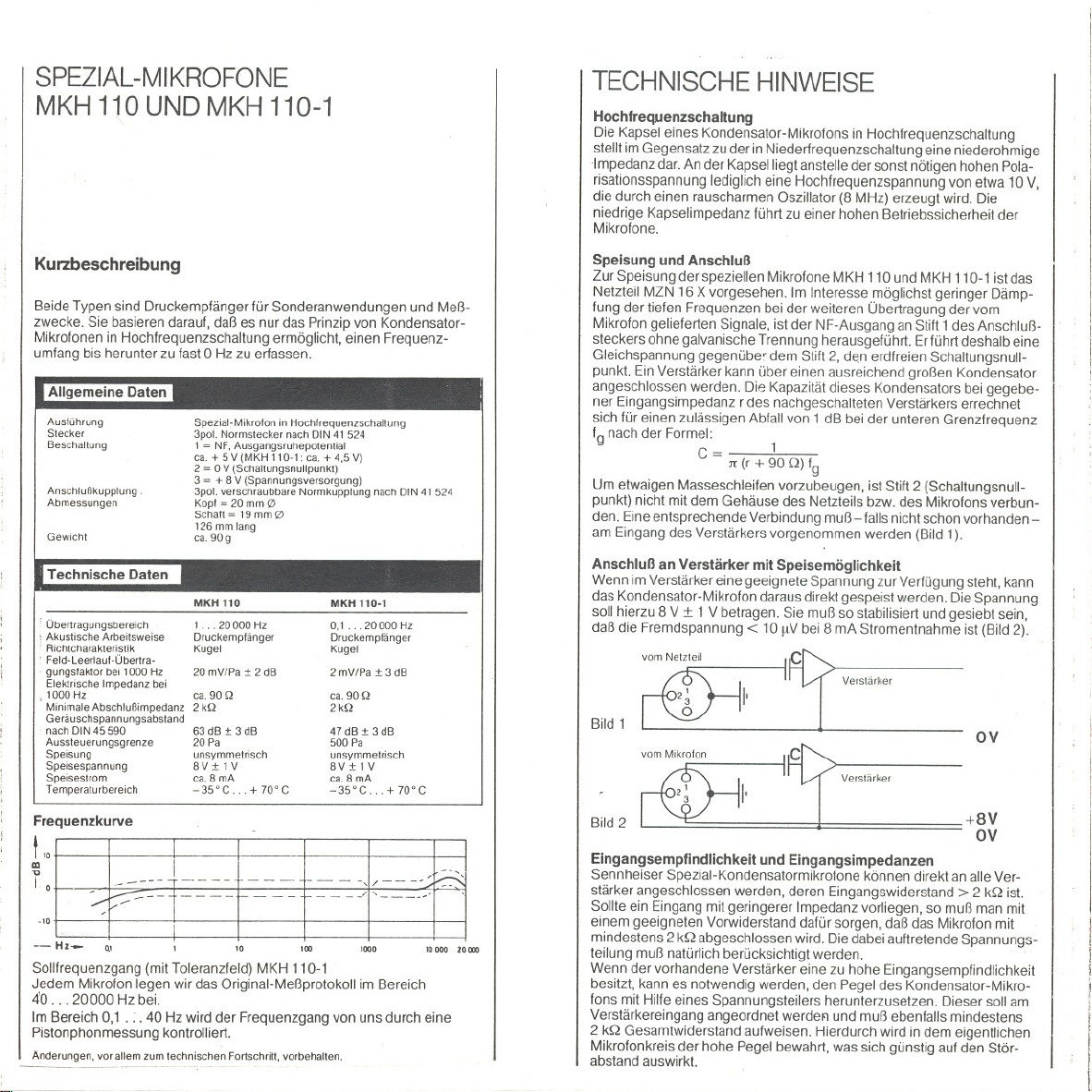
Frequenzkurve
-- Hz- Q'
Sollfrequenzgang (mit Toleranzfeld) MKH110-1
Jedem Mikrofon legen wir das Original-Meßprotokoll im Bereich
40. . . 20000 Hz bei.
Im Bereich 0,1 . - - 40 Hz wird der Frequenzgang von uns durch eine
Pistonphonmessung kontrolliert.
Änderungen, vor allemzum technischen Fortschritt,vorbehalten.
-~-----_.._------
Spezial-Mikrofon in Hochfrequenzschaltung
3pot.NormsteckernachDIN 41 524
1 = NF.Ausgangsruhepotential
ca. + 5 V(MKH 110-1: ca. + 4,5 V)
2 = 0 V (Schaltungsnullpunkt)
3 = + 8V (Spannungsversorgung)
3pot.verschraubbare Normkupplung nach DtN41 524
Kopf = 20mm 0
Schaft~ 19mm 0
126mm lang
ca. 90 9
MKH 110
1...20000Hz
Druckempfänger
Kugel
20 mV/Pa:!: 2dB
ca.90 Q
2kQ
63 dB :!:3 dB
20Pa
unsymmetrisch
8V:!:lV
ca.8 mA
-35'C. . + 70'C
10
MKH 110.1
0,1.. .20000 Hz
Druckempfänger
Kugel
2 mV/Pa:!: 3 dB
ca.90 Q
2kQ
47 dB :!:3 dB
500 Pa
unsymmetrisch
8V:!: 1 V
ca.8 mA
-35'C. . + 70'C
100
1000
10 000 10000
Speisung und Anschluß
Zur Speisung der speziellen Mikrofone MKH 110 und MKH 110-1 ist das
Netzteil MZN 16 X vorgesehen. Im Interesse möglichst geringer Dämp-
fung der tiefen Frequenzen bei der weiteren Übertragung der vom
Mikrofon gelieferten Signale, ist der NF-Ausgang an Stift 1des Anschluß-
steckers ohne galvanische Trennung herausgeführt. Erführt deshalb eine
Gleichspannung gegenübe' dem Stift 2, den erdfreien Schaltungsnulle
punkt. Ein Verstärker kann über einen ausreichend großen Kondensator
angeschlossen werden. Die Kapazität dieses Kondensators bei gegebe-
ner Eingangsimpedanz r des nachgeschalteten Verstärkers errechnet
sich für einen zulässigen Abfall von 1 dB bei der unteren Grenzfrequenz
fg nach der Formel:
Um etwaigen Masseschleifen vorzubeugen, ist Stift 2 (Schaltungsnull-
punkt) nicht mit dem Gehäuse des Netzteils bzw. des Mikrofons verbun-
den. Eine entsprechende Verbindung muß - falls nicht schon vorhanden-
am Eingang des Verstärkers vorgenommen werden (Bild 1).
Anschluß an Verstärker mit Speisemöglichkeit
Wenn im Verstärker eine geeignete Spannung zur Verfügung steht, kann
das Kondensator-Mikrofon daraus direkt gespeist werden. Die Spannung
soll hierzu 8 V :t 1 V betragen. Sie muß so stabilisiert und gesiebt sein,
daß die Fremdspannung< 10 IlV bei 8 mA Stromentnahme ist (Bild 2).
Bild 1
2
Bild
Eingangsempfindlichkeit und Eingangsimpedanzen
Sennheiser Spezial-Kondensatormikrofone können direkt an alle Ver-
stärker angeschlossen werden, deren Eingangswiderstand> 2 kQ ist.
Sollte ein Eingang mit geringerer Impedanz vorliegen, so muß man mit
einem geeigneten Vorwiderstand dafür sorgen, daß das Mikrofon mit
mindestens 2 kQ abgeschlossen wird. Die dabei auftretende Spannungs-
teilung muß natürlich berücksichtigt werden.
Wenn der vorhandene Verstärker eine zu hohe Eingangsempfindlichkeit
besitzt, kann es notwendig werden, den Pegel des Kondensator-Mikro-
fons mit Hilfe eines Spannungsteilers herunterzusetzen. Dieser soll am
Verstärkereingang angeordnet werdeFl und muß ebenfalls mindestens
2 kQ Gesamtwiderstand aufweisen. Hierdurch wird in dem eigentlichen
Mikrofonkreis der hohe Pegel bewahrt, was sich günstig auf den Stör-
abstand auswirkt.
c= 1
1t (r + 90 Q) fg
Verstärker
OV
Verstärker
+8V
OV
I
! I
! I
11
I.
Page 3

INSTRUMENTATIONMICROPHONES
MKH110ANDMKH110-1
Short Description
These microphones are especially designed pressure transducers lor
instrumentation purposes. Only the operating principle 01RF-condenser
microphones allows a Irequency response to extend down to 0 Hz.
Description
Outputplug
Wlring
Cableconneclor
Dimensions
Weight
Technical Data
Frequeneyresponse
Acoust:ealmode 01operation
Direetionaleharacteristie
Sensilivityat 1000 Hz
Eleetriealimpedance
al 1000 Hz
Minimalload impedanee
WeightedS/N ratioto
DIN45 590
MaximalSPL
Powering
Operatingvolt3ge
Currentdrawn
Temperalurerange
specialmicrophone in RF-technique
3-pln connector to DIN 41 524
1 = audio.nominalcircuit output voltageappx. + 5 V
(MKH 110-1: appx. + 4.5 V)
2 = 0 V(cireuit ground)
3 = + 8V (voltagesupply)
3-pin standardeonneetor10DIN41 524
Head = 20 mm 0
Tube = 19 mm 0
Length 126 mm
appx.90 9
MKH110
1.. 20000 Hz
pressuretransducer
omnidireelional
20 mV/Pa:t 2dB
appx. 90 Q
2kQ
63 dB :t 3 dB
20 Pa
unbalaneed
8V:t1V
appx.8 mA
-35'C . + 70'C
MKH 110-1
0.1...20000Hz
pressure transducer
omnidireetional
2mV/Pa:t3aB
appx.90 Q
2kQ
47dB:t 3dB
500 Pa
unbalaneed
8V:t 1V
appx.8 mA
-35'C. . + 70'C
TECHNICALNOTES
High Frequency Circuit
The capsule 01a RF-condenser microphone presents, contrary to
low Irequency circuits, a low impedance output. Instead 01the high
polarization voltage normally required, a high Irequency capsule needs
only a high Irequency voltage 01about 10 V, wh ich is produced by a
built-inlownoiseoscillator(8 MHz).The low capsule impedance leads 10
a high perlormance reliability 01the microphones.
Powering and Connection
For powering the special microphones MKH 110 and MKH 110-1 a
corresponding power supply MZN 16 X is provided. In order that the
Irequency response cannot be limited by the value 01the output coupling
capacitor, the audio output on pin 1 01the microphone is connected
directly to the output amplifier without a blocking capacitor. There is,
therelore, a DC-voltage on this pin against ground. An amplilier may be
connected using a corresponding capacitor. With a given amplilier input
impedance rand the -1 dS point at the lower Irequency limit Ig, the
capacitor value is determinated by the lormula: 1
. - Jt(r
:To prevent ground loops, pin 2 (circuit ground) is not connected with the
,housing 01the power supply respectively the microphone. Acorres-
ponding connection - il not already incorporated - has to be providep
(Fig.1).
Connection to Amplifiers with Powering Facilities
11anappropriate voltage source isavailable in the amplilier the condenser
microphone can be powered directly. The voltage should be 8 V :t 1 V.
It should be so stabilised and liltered, that the unweighted noise voltage
is< 10 ftV at 8 mA current consumption (Fig. 2).
Irom power supply
.~
2~ I'
I(QJI
Fig.1
.
C-
+ 90 Q) Ig .
amplifter
ov
amplrller
Frequency Response
~.:Ek~.~-~~~t~--l~.~I:~~~~
- Hz- QI I 10 100 1000 10000 '0000
Standard Irequency response with tolerance limits MKH 110-1.
The original diagram is delivered with each microphone 01this type,
measured lrom 40 to 20000 Hz.
The Irequency response in the range 010.1 Hz to 40 Hz is checked with
a piston-phone by uso
Wereserve the fight to alter specitications.in partieularwith regard to technieallmprove-
menls.
Fig.2
Input Sensitivity and Input Impedance'
Sennheiser special condenser microphones can be connected directly to
all amplifiers whose input impedance is > 2 kQ. 11the input impedance is
lower, a resistor 01appropriate value should be placed in series with the
microphone to provide correct matching. The voltage division caused by
this series resistor must 01course be considered.
11the amplilier being used has a too high input sensitivity, it can be
' necessary to reduce the output voltage Irom the microphone by means 01
I
i a voltage divider. This should be built atthe amplilier input and must have
a total impedance 01at least 2 kQ. Sy this means the large signal on the
microphone cable is maintained up to just belore the amplilier, wh ich
I
helps to increase the signal to noise ratio.
+8V
OV
Page 4

MICROPHONESSPECIAUX
MKH 110 ET MKH 110-1
Descriptionabregee
Les deux versions sont des capteurs de pression pour des applications
speciales et des mesures acoustiques. Seuls en effet les microphones
electrostatiques a montage HF sont capables de couvrir des frequences
tendant vers 0 Hz.
Caracteristiques generales
Type
Fiche
Broehage
Conneeteur
Oimensions
Poids
Caracteristiques techniques
Bandepassante
Prineipeaeoustique
Direetivlte
Faeteurde transmission
avide a 1000 Hz
Impedaneeeleetrique
a1000Hz -
Pluspetiteimpedaneede
chargeadmissible
Rapportsignal/bruit selon
DIN45590
Niveaumax.
Alimentation
Tensiond'alimentation
Courantd'alimentation
Plagede temperatures
mierophonespecialHF
tnpolalrevlssant normaliseeselon DIN 41 524
1 = BF.potentiel de reposde sortie env. + 5V
(MKH 110.1: env. + 4.5 V)
2 = 0 V(point zero)
3 = + 8V (alimentation)
tripolairevissant normaliseselon DIN 41 524
tete = 20 mm 0
tube=19mm0
longueur = 126mm
env. 90g
MKH110
1. .20000Hz
eapteurde pression
omnidireetlonnelle
20 mV/Pa :t 2 dB
env. 90 Q
env. 2 kQ env.2 kQ
63 dB :t 3 dB
20 Pa
asymetrique
8V:t1V
env. 8 mA
-35°C. + 70°C
MKH 110-1
0.1.. 20000 Hz
eapteurde pression
omnidirectionnelle
2 mV/Pa :t 3dB
env.90 Q
47dB:t3dB
500 Pa
asymetrique
8V:t 1 V
env. 8 mA
-35°C. . + 70°C
i INOICATIONSOESERVICE
Montage haute frequence
Contrairement au montage basse frequence, la capsule d'unmicro
electrostatique a haute frequence presente une faible impedance. A
la place de la tension de polarisation relativement elevee, la capsule
n'est soumise qu'a une faibletension d'environ 10 V,foumie par un
oscillateur a quartz (8 MHz).La faible impedance du systeme a pour
consequence un bruit de fond tres faible et une haute fiabilitedes
microphones.
Alimentation et branchement
Pour alimenter les micros speciaux MKH 110 et MKH 110-1 nous
avons prevu I'alimentation MZN 16 X. Pour atteindre une attenuation
minimale des basses frequences a la retransmission des signaux, la
sortie BF au point 1 de I'embasse de branchement ne comporte pas
de separation galvanique. Par rapport au point 2 qui est le point zero
du circuit (sans prise a lamasse) le point 1 sera donc a tension con-
tinue. En utilisant comme intermediaire un condensateur de grosse
capacite, on pourra se raccorder a un amplificateur. Pour une impe-
dance d'entree r de I'amplificateur, la capacite de ce condensateur,
avec une attenuation de 1 dB pour la frequence limite inlerieure Ig,
se calcule selon la formule suivante:
C = Jt(r + 90 Q) fg
Afin d'eviter les bouGIes de masse eventuelles, le point 2 (point zero)
n'est pas relie au boitier de I'alimentation resp. du micro. Une connexion
correspondante doit - sinecessaire -etre faiteaI'entree de I'amplificateur
(Fig.1).
Branchement ades amplificateurs avec possibilite d'alimentation
SiI'amplificateur possede une tension convenant, le micro electrostatique
peut en etre alimente directement. La tension doit etre de 8 V :!::1V. Elle
doit etre stabilisee et filtree de teile maniere que la tension non ponderee
soit< 10 ftV pour un courant de 8 mA (Fig. 2').
Fig.1
1
ampliliealeur
ov
amplilieateur
.,
~~l==~l.~~=--~:l==~~
-Hz-
~I 10 100 1000 '0000 20 000
Courbe de reponse de consigne (avec tolerances) MKH 110-1 .
Chaque microphone est livre avec I'original du proces-verbal des
mesures entre 40 et 20000 Hz.
Entre 0,1 et 40 Hz la reponse en frequence est contrölee en usine
avec un pistonphone.
Modllieations.surtout dans I'interet du progres teehnique. reservees.
Fig.2
Sensibilite d'entree et impedances d'entree
Les micros speciaux de Senn heiser electronic peuvent etre branches a
+8V
OV
tous les amplilicateurs dont I'impedance d'entree > 2 kQ. Si on est en
presence d'une impedance inferieure, iI faut choisir une resistance
additionnelle convenant afin que le micro «voie.. une charge de 2 kQ au
moins. Ladivision de tension qui s'ensuit doit etre prise en consideration.
Si I'amplificateur present possede une impedance trop elevee il peut etre
necessaire de diminuer la tension du microphone electrostatique a I'aide
d'un diviseur de tension. Celui-ci doil etre situe a I'entree de I'amplifica-
teur et doit avoir un impedance totale d'au moins 2 kQ. De cette fayon,
le niveau eleve est mainteou pour le circuit du micro proprement dit, ce
qui est propice a un rapport signal/bruit eleve.
Page 5
I
I
I
I
I
I
I
I
,
I
I
t
I
I
,
I
I
I
SENNHEISERELECTRONICKG
0-3002 WEOEMARK
TELEFON05130/600-0
TELEX924623
TELEFAX05130/6312
 Loading...