

Page 1
Page 2
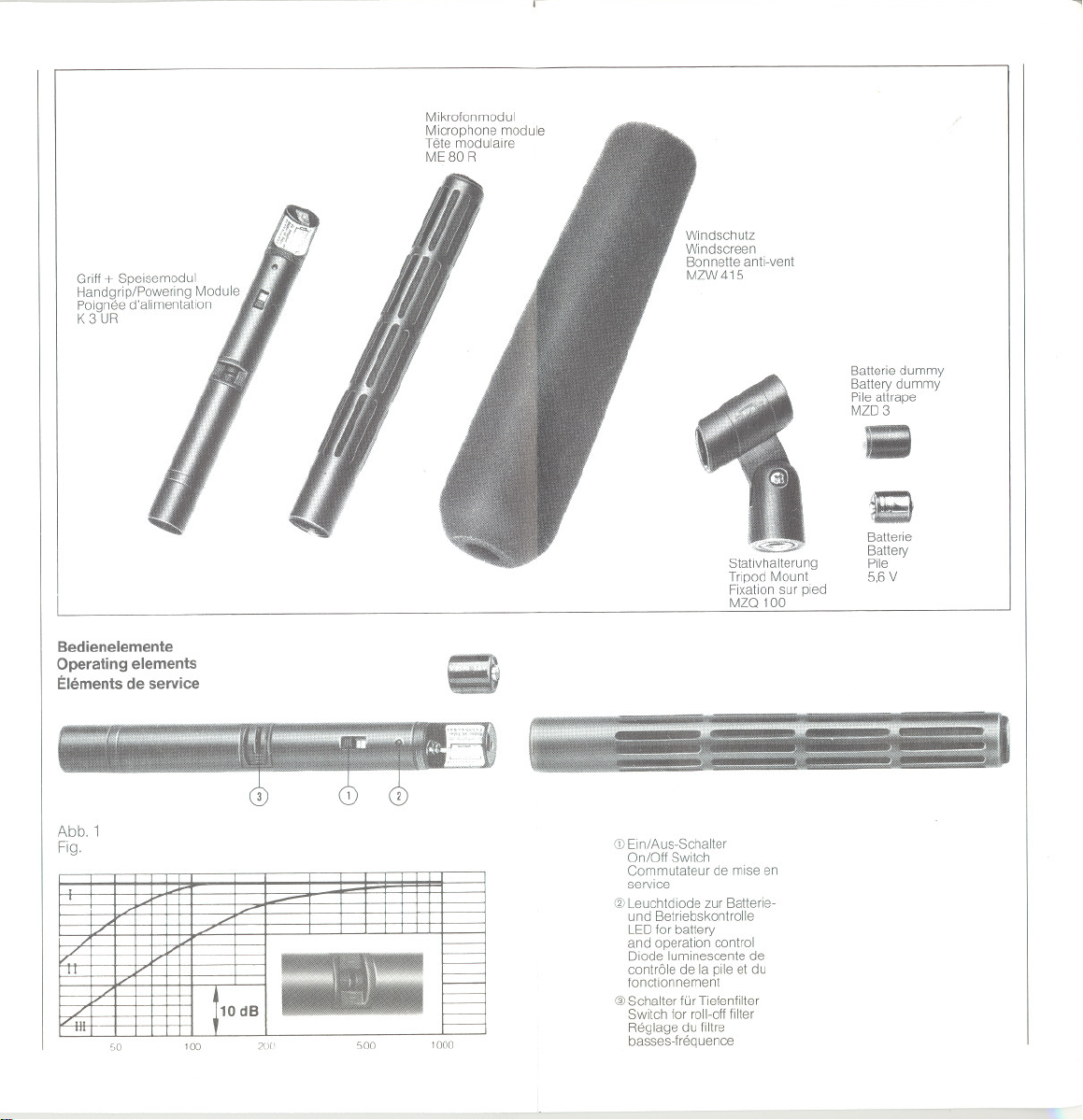
Griff + Speisemodul
Handgrip/Powering Module
Poignee d'alimentation
K3 UR
Mikrofonmodul
Microphone module
Tete modulaire
ME 80 R
I
Windschutz
Windscreen
Bonnette anti-vent
MZW 415
Batterie dummy
Battery dummy
Pile attrape
MZD3
Batterie
Battery
Stativhalterung
Tripod Mount
Fixation sur pled
MZO 100
Pile
5,6V
-,
Bedienelemente
Operating elements
Elements de service
Abb.1
Fig.
',0 100
200 500
1000
- --'--
CDEin/Aus-Schalter
On/Off SWltch
Commutateur de mise en
service
@ Leuchtdiode zur Batterie-
und Betrrebskontrolle
LED fm battery
and operation control
Diode luminescente de
contröle de la pile et du
fonctionnement
@Schalter für Tiefenfilter
Switch fm roll-off filter
Reglage du filtre
basses-frequence
Page 3
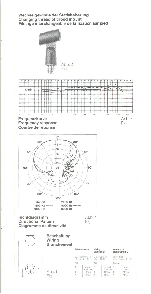
Wechselgewinde der Stativhalterung
Changing thread of tripod mount
Filetage interchangeable de la fixation sur pied
Abb.2
Fig.
.. -
I::::::!::ci-c=
110dB f--
==
"-
r====
f--
i--- i j
I-'--
-
---
--
-.
cc.:
=-- -
0 - - _0 _.-
..0 ----n-
t
_n
t=t--
--+
1=>
Frequenzkurve
Frequencyresponse
Courbe de reponse
-1= =
...
n
+
--'""
.n
-
ci
==
Abb.3
Fig.
i
90°.
"
250 Hz 2000 Hz -
500 Hz -.- 4000 Hz _.-
1000Hz- 8000Hz_n-
Richtdiagramm
Directional Pattern
180"'
Diagramme de directivite
Beschaltung
Wiring
Branchement
Abb.5
Fig.
90°
Abb.4
Fig.
SehellScheme U
3po1ige' Cannon- 3-",n Cannon
Sied«< XlR-3
S,,"
Wi,ing
Diag,em U
pl"9 XLR-3
S,.
Scheme de
.,anehement U
bome Inpo-
I
. laireCannonXLR-3
Contact
ma~~e.
bo"'"
8FI+1
BFI-)
Page 4
ELEKTRET-KONDENSATORMIKROFON
MKE 80 R
Lieferumfang: Griff + Speisemodul K 3 UR
Das MKE 80 R ist ein Elektret-Kondensatormikrofon, das »kom-
plett« ist. »Komplett«
gebrauchsfertige Einheit darstellt, die speziell für den Einsatz an
häufig wechselnden Aufnahmeorten ausgelegt ist. Lediglich
das Anschlußkabel muß ergänzt werden.
Die garantierten Daten des MKE 80 R welsen es als ein quali-
tativ hochwertiges Mikrofon aus, das die hohen Ansprüche
professioneller Anwender an die Tonqualität erfüllt.
Das MKE 80 R besteht im wesentlichen aus den Komponenten
+ Speisemodul K 3 UR und Mikrofonmodul ME 80 R.
Griff
Das Mikrofonmodul ist eine Kombination von Druckgradienten-
und Interferenzempfänger, dessen Richtcharakteristik für Fre-
quenzen unterhalb 2000 Hz die Form einer Superniere aufweist
und für Frequenzen oberhalb 2000 Hz die einer Keule. Die
resultierende Richtcharakteristik und der damit verbundene
hohe Bündelungsgrad sorgen dafür, daß Schallereignisse
außerhalb der Haupteinspracherichtung wirkungsvoll aus-
geblendet werden, so daß selbst bei größeren Besprechungs-
abständen gute Aufnahmen möglich sind. Aufgrund dieser
Eigenschaft läßt sich das Mikrofon vorteilhaft für Interviews,
Reportagen und in der Filmproduktion einsetzen.
Die zweite Komponente des MKE 80 R ist das Griff + Speise-
modul. Eine im Modul befindliche 5,6-V-Batterie versorgt das
Mikrofon mit der erforderlichen Betriebsspannung. Neben der
Spannungsversorgung aus der Battene besteht auch die Mög-
lichkeit der Phantomspeisung (12
Bedienung
Einsetzen der Batterie und Batteriekont"olle
Die 5,6-V-Batterie (z. B. Varta 23 PX) wird entsprechend der
Polaritätsangabe auf dem Battenefach-Aufkleber eingesetzt.
Kontaktangabe und Funktion können durch kurzzeitiges Ein-
und Ausschalten überprüft werden. Leuchtet die Diode (2) kurz-
zeitig auf, ist die Batterie richtig eingesetzt worden. Anschlie-
ßend wird das Mikrofonmodul mit dem Griff + Speisemodul
verschraubt.
Der Ein-lAus-Schalter (1) Ist so ausgelegt, daß beim Einschal-
ten (rotes Feld sichtbar) und Ausschalten des Mikrofons eine
zur Batteriekontrolle eingebaute Leuchtdiode (2) kurzzeitig hell
aufleuchtet, wenn die Betriebsspannung für das Mikrofon aus-
reichend ist (Abb. 1).
Läßt die Helligkeit erkennbar nach, ist noch eine Reserve von
ca. 20 Stunden vorhanden. Die Batterie sollte bei nächster
Gelegenheit gewechselt werden. Die normale Lebensdauer der
Batterie beträgt etwa 600 Stunden. Ersatzbattenen sind im ein-
schlägigen Fachhandel erhältlich. Zur Vermeidung einer unnöti-
gen Batterieentladung sollte das Mikrofon ausgeschaltet wer-
den, wenn es nicht benutzt wird.
Bei Phantomspeisung dient die LED der Betnebskontrolle.
Mikrofonmodul ME 80 R
Batteriedummy MZD 3
Stativhalterung MZO 100
Windschirm MZW 415
Batterie 5,6 V PX 23
- das heißt, daß dieses Mikrofon eine
- 48 V).
4
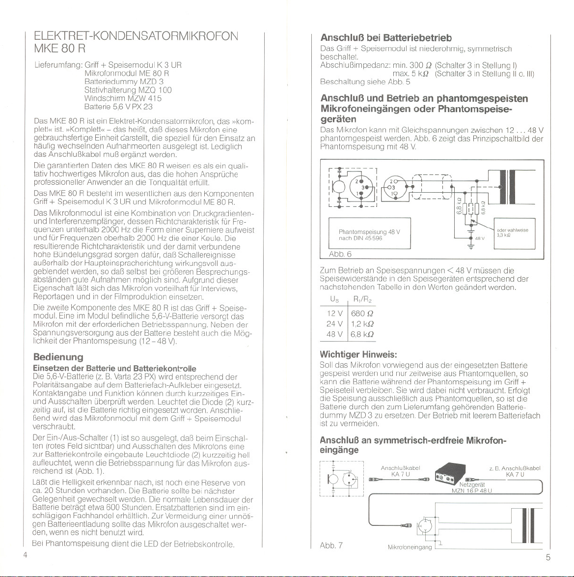
Anschluß bei Batteriebetrieb
Das Griff +Speisemodul ist niederohmig, symmetrisch
beschaltet.
Abschlußimpedanz: min. 300 Q (Schalter3 in Stellung I)
Beschaltung siehe Abb. 5
Anschluß und Betrieb an phantomgespeisten
Mikrofoneingängen oder Phantomspeise-
geräten
Das Mikrofon kann mit Gleichspannungen zwischen 12 .. . 48 V
phantomgespeist werden. Abb. 6 zeigt das Prinzipschaltbild der
Phantomspeisung mit 48 V.
~ 1
i
I 2 I
I 3 I
: I I
~
L+-- u:
Phanlomspeisung 48 V
nach DIN 45596
Abb.6
Zum Betneb an Speisespannungen < 48 V müssen die
Speisewiderstände in den Speisegeräten entsprechend der
nachstehenden Tabelle in den Werten geändert werden.
Us R1/R2
12V 680 Q
24V 1,2kQ
48 V 6,8 kQ
Wichtiger Hinweis:
Soll das Mikrofon vorwiegend aus der eingesetzten Batterie
gespeist werden und nur zeitweise aus Phantomquellen, so
kann die Battene während der Phantomspeisung im Griff +
Speiseteil verbleiben. Sie wird dabei nicht verbraucht. Erfolgt
die Speisung ausschließlich aus Phantomquellen, so ist die
Battene durch den zum Lieferumfang gehörenden Batterie-
dummy MZD 3 zu ersetzen. Der Betrieb mit leerem Batteriefach
ist zu vermeiden.
Anschluß an symmetrisch-erdfreie Mikrofon-
eingänge
r---r ,
i
: ' :~~ '\1'".- KA7U
: ,: '. Netzgerät
~
~---L--- --_J MZN16P48U
Abb.7
i Anschlußkabel
max.5 kQ (Schalter3 in Stellung IIo. 111)
[
z. B. Anschlußkabel
.
M"ro"""~~
nr
5
Page 5

Anschluß an unsymmetrische Mikrofon-
eingänge
,---r--- ,
i
: ,:~~.~.~.-
: ,:
~
L_--L--- ---J MZN 16 P 48 U
Abb.8
Anschluß an Tonaufzeichnungsgeräte mit
Speisemöglichkeit
r---r '
:
: ,: KA7 U
I I--
I ,I
I I
~
"---L--- ---J
Abb,9
i Anschlußkabel
i Anschlußkabel
"
NF
MIkrofoneingang
" Netzgerät
Besprechen des Mikrofons
Das MKE 80 R hat einen hohen Bündelungsgrad, d. h. das
Mikrofon nimmt überwiegend Schallereignisse auf, die direkt
von vorn auf das Mikrofon treffen (Abb. 4), Beim Ausrichten des
Mikrofons ist deshalb darauf zu achten, daß es möglichst in
Richtung der aufzunehmenden Schallquelle weist.
Tiefenfilter
Zur Reduzierung tieffrequenter Störeinflüsse durch Hantie-
rungsgeräusche, Trittschall- und Windgeräusche besitzt das
+ Speiseteil ein in 3 Stufen schalt bares Filter (3). Die
Griff
Absenkung im tieffrequenten Bereich beträgt in SchaltersteI-
lung 1I= 7 dB und in Schaltersteilung III= 20 dB bezogen auf
50 Hz (Abb. 1). In Schaltersteilung I ist das Filter ausgeschaltet,
der Frequenzverlauf wird nicht beeinflußt. Das Tiefenfilter unter-
drückt jedoch nicht nur Störungen, sondern beschneidet natür-
lich auch einen Tell des sonst nutzbaren Anteils im Tiefen-
bereich. Es sollte daher wirklich nur dann eingesetzt werden,
wenn es sich um Störgeräusche handelt, die durch andere
Maßnahmen nicht zu unterdrücken sind. Bei Aufnahmen im
Freien sowie bei Nahbesprechung ist stets der zum liefer-
umfang gehörende Windschutz MZW 415 einzusetzen, um ver-
meidbare Störungen ohne Einsatz des Tiefenfilters wirksam zu
reduZIeren.
Befestigung
Zur Befestigung des Mikrofons auf Stativen, Tischfüßen etc. mit
Yg",Y2"oder %"-Gewinde dient die mitgelieferte Stativklemme
MZO 100 (Abb. 2). Weitere Befestigungsmöglichkeiten sind im
Abschnitt »Zubehör" aufgeführt.
6
r
Technische Daten
Ubertrag ungsbereich
Akustische Arbeitsweise
Rlchtcharakterlstlk "'"
FeIdIeerlauf-Ubertragun9sfaktor
bei1000 Hz ,
Elektrische Impedanz
Mln, AbschlußImpedanz
Geräuschspann ungsabstand
nach DIN 45590
Stecker, ,
Steckerbeschaltung
Anschlußkupplung
Stromversorgung
Abmessungen in mm
Gewicht
Änderungen. vor allem zum technischen Fortschritt,
vorbehalten,
EmpfohlenesZubehör
Netzgerät MZN 16 P 48 U
(Art.-Nr.1241)
Stromversorgung für 48-V-
Phantomspeisung nach
DIN 45596. Ermöglicht
Betrieb von zwei Mikrofonen
mit XLR-Steckverbindern
(System Cannon). LED-
Betriebsanzeige. Netzspan-
nung 85-265 V/50-60 Hz.
Federhalterung MZS 415-3
(Art.-Nr.1956)
Federhalterung mit Yg"-Innen-
gewinde, passend für alle Sta-
tive, Tischfüße und Ausleger
mit Yg"-Gewinde. Mlkrofonhal-
terung gegenüber Außenge-
häuse schwingend gelagert.
Länge: 80 mm
Durchmesser: 35 mm
Federhalterung MZS 416
(Art-Nr.2071)
Halterung mit gummigelager-
ten Kunststoffklammern. Sehr
gute Körperschalldämpfung.
Mit Yg"-Gewindebohrung zur
Befestigung an Mikrofonan-
geln, Decken- oder Wandbe-
festigungen oder auf Stativen.
Länge: 350 mm
Gewicht: 200 g
50- 15000 Hz
Druckgradlenten-Interterenz-
empfänger
Supernlere/Keule
0,5 mVI,ubar'" 5 mV/Pa
ca. 200 Q
ca.300 Q (SchaltersteIlung I)
ca. 70 dB
3pol. Cannon XLR-3
1 - Gehäuse. 2 - NF,3 - NF
3pol. Cannon-Kupplung
XLR-3-11-C
5,6-V-Batterie-Spelsung
oder Phantomspeisung
nach DIN45596
für 12 .. . 48 V
ohne Umschaltung
19/22 (Z5x 313
ca. 205 g
MZN 16 P48 U
MZS415-3
~
MZS416
7
Page 6

MZG415-3
MZB415
~ ,
tQ M
L ~
XLR-3-11 C XLR-3-12 C
~
l- -~ ~ - - - --- -- - -- - - - -- ~ ~ - - J
XLR-3-11 C
T 3260001
8
Gelenkarm MZG 415-3
(Art.-Nr. 1955)
In Verbindung mit der Feder-
halterung MZS 415-3 dient
der Gelenkarm zur Befesti-
gung von Mikrofonen auf Sta-
tiven und Tischfüßen. Durch
ausschraubbaren Gewin-
deeinsatz passend für %", %"
oder Y2"-Gewinde. Gelenk um
1800 schwenkbar.
Farbe: schwarz.
Mikrofonangel MZB 415
(Art.-Nr. 0972)
Zweiteilige Glasfiber-
Mikrofonangel. Mikrofonbefe-
stigung mit einstellbarem Nei-
gungswlnkel und %"-
Gewinde. Aufnahmerichtung
durch Drehen des Angelsta-
bes um 3600 zu verändern.
Länge: min. 120 cm
Gewicht
Tischfuß MZT 100
(Art.-Nr. 1883)
Stabiler, weich umschäumter
Tischfuß mit hoher Standfe-
stigkeit und guter Körper-
schalidämpfung. Befesti-
gungsschraube %".
Tischfuß MZT 441
(Art.-Nr.0799)
Stabiler, standfester Tischfuß
aus Metall, mit %"-Befesti-
gungsschraube.
Farbe: grau.
Passend für MZG 415-3.
Anschlußkabel KA 7 U
(Art.-Nr.1777)
Kabel zum Anschluß von
Mikrofonen mit 3pol. XLR-3-
Stecker, System Cannon, an
symmetrische Mikrofonein-
gänge mit 3pol. XLR-Buchse,
System Cannon.
Kabellänge: 7,5 m.
Anschlußkabel KA 7 UN
(Art.-Nr. 2157)
Kabel zum Anschluß von
Mikrofonen mit 3pol. XLR-3-
Stecker, System Cannon, an
symmetrische Mikrofonein-
gänge mit 3pol. verschraub-
barer Buchse nach
DIN 41 524.
Kabellänge: 7,5 m.
max. 340 cm
ca. 640 9
ELECTRET CONDENSER MICROPHONE
MKE 80 R
Delivery Includes: handgrip/powenng module K 3 UR
The MKE 80 R is an electret condenser microphone. which is
"complete". "Complete" means that the microphone is a ready
far use unlt which is specially intended to work with at often
changing recarding places. Only the connecting cable has to
be added.
The guaranteed data of the MKE 80 R show that it is a high
qualified microphone which meets the high demands to sound
quality of professional users.
The MKE 80 R essentlally consists of the handgrip/powering
module K 3 UR and the microphone head ME 80 R.
The microphone combines the characteristics of apressure
gradient transducer with those of an interference receiver. Its
dlrectional pattern far frequencies below 2000 Hz has the
shape of a super cardloid pattern and becomes club-shaped
for frequencies above 2000 Hz. This directional pattern effi-
Clently eliminates all interfering and background noise thus
guaranteeing good recardlngs even at larger distances. It
should be used far interviews, reporting and in film production.
The second component is the handgrip/powering module,
which contalns a 5.6 V battery far powering the microphone
module. Besides battery powering, phantom powering is also
possible (12- 48 V).
Operation
Inserting the battery and battery voltage check
The 5.6 V battery (e. g. Varta 23 PX) is to be inserted according
to the label In the battery compartment. The battery contact and
function can be checked switching the mlcrophone on and off.
If the LED (2) Iights up, the battery has been inserted correctly.
Then the microphone module and the handgrip/powering
module are to be assembled.
The condltion of the battery IS checked every time the
microphone is sWltched on (red mark visible) ar off. When
switching on, a LED (2) lights up, Indicatlng sufficient supply
voltage (fig. 4).
Ifthe LED becomes dirn, the battery should be replaced. But
there is still areserve of approx. 20 h left - enough time to
optain a new battery. The normal operating time with one bat-
tery is approx. 600 h. New batteries are avallable from your
local dealer. When the microphone is not in use it should be
switched off to prevent the battery from belng unnecessarily
drained. For phantom powering the LED serves as an operation
control.
microphone module ME 80 R
battery dummy MZD 3
tripod mounting MZO 100
windscreen MZW415
battery 5.6 VPX23
9
Page 7

Connection with battery operation
The handgrip/powering module is low-impedance
and balanced.
Load impedance: min. 300 Q (switch 3 in position I)
Wiring see lig. 5.
ConnE!ction and operation at phantom-powered
microphone inputs or phantom-powering units
The microphone can be phantom-powered with DC-voltages
between 12. , .48 V. Fig. 6 shows the basic Clrcuit diagram lor
phantom powering with 48 V.
~ l
i
: 2 I
I 3 I
I 1 I
- - -_J
~
L+ I
Phantom-powering 48 V
accordmg to OIN 45596
Fig, 6
For operation with voltages 01 less than 48 V,the supply voltage
resistors in the supply device must lirst be changed over to the
values listes in the table below.
Us
R/R2
12V1680 Q
24 V 1,2kQ
48 V 6,8 kQ
Important note:
Should the microphone malnly be used with battery supply and
seldom with phantom powering, the battery can remain in the
handgrip/powering module during phantom powering. It will
not be drained. I1the microphone is exclusively phantom
powered the battery should be replaced by the battery dummy
MZD 3 included. Do not operate the mlcrophone with empty
battery compartment.
Connection to balanced-floating microphone
inputs
r-nr '
,
: 'I KA 7 U connectmg
: ' :-- .,.'@ KA7U
" ,I-- -
:' powersupplyunlt
~
L---L--- ---J MZN 16 P 48 U
max.5 kQ (switch 3 in position IIor 1'1)
~ 4SV
: connectlng cable
'
~
'
oe
3,3 kQ
[
'
,
Connection to unbalanced microphone inputs
r-
n n, connectinj U
r , : cableK~1,:-
i'i
' ,
~
L_--L-- m~
~
.,
]
\
..
Fig.8
Connection to sound recorders with supply
possibility
rn-rn_nu, connecting
I
, ,
, .,--
~
lmL--- --_J
Fig.9
Using the microphone
The MKE 80 R has a high sound directlonality, i,e. it primanly
picks up sound sources which are directly In Iront 01the micro-
phone (Iig. 4), Therelore, the mlcrophone should be directed in
direction to the sound source.
Roll-off filter
For reducing interferences caused by (Ior example) lootlall,
wind or handling noise the handgrip/powering module leatures
a 3-positlon switchable roll off lilter. Position II brings about a roll
off 017 dB and position 1'1a reduction 0120 dB at 50 Hz (Iig. 1).
In position I the lilter IS sWltched off, thus ensunng a Ilat
Irequency response, However, the roll off lilter reduces not only
Interfering noise, but also causes a reduction 01part 01the
otherwise useable low Irequency range, Therelore, the roll off
Illter should be used only I1interfenng noises cannot be ellmi-
nated by other means, For outdoor recording and close miking
the use 01the wlndscreen MZW 415 IS recommended In order
to effectively suppress avoldable interference without activating
the roll off lilter.
e
. : cableKA7U
"
,
",.'@e-
.
AF
microphone input
"
' unltMZN16P48U
,
power supply
)
[
Mounting
The quick release clamp MZO 100 is supplied with every mlcro-
phone enabllng it to be mounted on all tripods, desk stands
Fig.7
10
"'""',:::C-- ~
Input~
r
etc, wlth a SIg",Y/ or %" thread (Iig. 2). Further accessories are
Iisted under the appropriately headed chapter.
11
Page 8

Frequency response. . .
Acaustical mode ot aperatlan
Dlrectlanal charactenstic
Sensitivltyat 1000 Hz
Output impedance .
Minimum load impedance .
S/N accordlng ta DIN 45590
Cannectar. .
Pin cannections
Cable connector
Pawer supply
Dimensians in mm
Weight
We reserve the right to alter specifications, especlally with regard
to technical improvements.
50-15000Hz
pressure-gradient
Interterencetransducer
super cardiold/club
0,5 mV/I'bar "'" 5 mV/Pa
approx. 200 Q
approx. 300 Q (switch position I)
approx. 70 dB
3-pln, Cannon XLR-3
1 - hauslng, 2 - AF, 3 - AF
3-pin, Cannon-canneclor
XLR-3-11-C
5.6V battery powenng
or phantam-powenng
to DIN45596
tar 12 48 V,
seit adjusting
19/22 (2)x 313
approx. 205 9
R~commanded Accessories
MZG415-3
MZB415
Swivel adapter MZG 415-3
(Art.-No. 1955)
In connection with the shock
rnount MZS 415-3 the swivel
adapter is lar mounting micro-
phones on tripods and desk
stands. The thread insert lits
to %", %" ar Y2"threads.
Swivel rotatable about 1800.
Colour: black.
Telescopic microphone
boom MZB 415
(Art.-No. 0972)
Telescopic glass libre rnicro-
phone boorn. Microphone
mounting with adjustable tilt
angle and %" thread. Pick-up
direction changeable through
3600. by turning the boorn.
Length: rnin. 120 crn
Weight:
max. 340 cm
approx. 640 9
Power supply unit
MZN 16 P48 U
(Art.-No.1241)
Power supply unit lor 48 V -
phantom-powering according
to DIN 45596. For powering
two microphones. LED lunc-
tion switch. Supply voltage
85-265 VI 50-60 Hz.
Shock mount MZS 415-3
(Art.-No. 1956)
Shock mount with %" internal
thread, lits to all tripods, desk
stands and booms with %"
thread. The internal miero-
phone mount is suspended
away Irom the outer tube.
Length: 80 mm
Diarneter: 35 rnm
Shock mount MZS 416
(Art.-No. 2071)
Shock mount with rubber
suspended plastic clamps.
Excellent handling noise
darnping. %" thread lar
mounting on rnicrophone
boorns, sealing- or wall
attaehrnents or on tripods.
Length: 350 mrn
Weight: 200 9
12
~
MZN 16 P 48 U
MZS415-3
MZS 416
r ,
tO 01
L ~
XLR-3-11 C XLR-3-12 C
~
lu~~u--_u_u u_n- ~~uJ
XLR-3-11 C T 3260001
Desk stand MZT 100
(Art.-No. 1883)
Stable desk stand, soft
embedded in plastic, with
high stabillty and very good
handling noise suppression.
Mounting screw %".
Desk stand MZT 441
(Art.-No. 0799)
Very stable metal desk stand
with :;;8"mounting serew.
Suitable lar MZG 415-3.
Colour: grey.
Connecting cable KA 7 U
(Art.-No. 1777)
Cable lar connection rnicro-
phones with 3-pin XLR-3 plug,
system Cannon, to balanced
rnicrophone Inputs wlth 3-pin
XLR socket, system Cannon.
Cable length: 7.5 rn
Connecting cable KA 7 UN
(Art.-No.2157)
Cable lar connection 01micro-
phones wlth 3-pln XLR-3 plug,
system Cannon, to balanced
rnicrophone inputs with 3-pin
screwable socket according
to DiN 41 524.
Cable length: 7.5 rn
13
Page 9

MICROPHONE ELECTROSTATIQUE
A ELECTRETMKE80 R
La livraison comprend:
Le MKE 80 Rest un microphone electrostatique 8 electret
«complet». «Complet» c'est-8-dire que le microphone repre-
sente une unite prete pour I'utilisation, specialement pour des
enregistrement aux lieux qui change nt souvent. 11faut seule-
me nt suppleer le cable de raccordement.
Le MKE 80 Rest un microphone de haute qualite, garantit par
ses caracteristiques techniques, qui satisfait les pretentlons des
utilisateurs professioneis.
Le MKE 80 R se compose de la poignee d'alimentatlon K 3 UR
et de la tete modulaire ME 80 R.
La tete modu!aire est une combinalson de capteur de gradient
de pression et de capteur d'interference dont la directivite est
super-cardioide pour les frequences Inferieure 8 2000 Hz et en
forme de lobe pour les frequences superieures 8 2000 Hz. La
directivite et le taux de directlvlte eleve resultants de cette
combmaison, empechent que les sons ne provenant pas de la
direction principale d'enregistrement attelgnent le pavillon
acoustique. On obtient ainsi, meme avec une distance bouche-
micro elevee, de bons resultats. Cette propriete permet d'utiliser
la microphone pour des interviews, des reportages et en
production de film.
Le deuxieme composant du MKE 80 Rest la pOlgnee d'alimen-
tation. Elle contient une pile de 5,6 V qui alimente le micro. 11est
egalement possible d'utillser une alimentation fantöme
(12-48 V).
Mode d'emploi
Mise en place et contröle de la pile:
La pile de 5,6 V (p. ex. Varta 23 PX) est placee dans le comparti-
ment, dans le sens indique par la polarite. Le bon contact et le
fonctionnement de la pile seront testes en actionnement I'inter-
rupteur. Si la diode (2) s'allume pour un temps court, la pile est
bien placee.
poignee.
Le commutateur de service (1) permet un contröle de la pile. En
mettant le microphone en service (champ rouge visible) ou en
I'arretant, la diode luminescente (2) eclaire fortement, SI la
tension necessaire au fonctionnement du micro est 18(flg. 1).
Lorsque la luminosite s'affalbllt, la pile possede encore une
reserve d'environ 20 h. Elle devra etre changee 8 la prochame
occaslon. La duree de vie normale d'une pile, que I'on trouve
en commerce attemt env. 600 heures. Pour eviter un usage
inutile de la pile, le micro devra etre mls hors service lorsqu'il
n'est pas utilise.
En cas d'alimentation fantöme, la LED sert de contröle de
fonctlonnement.
14
La tete modulalre sera alors revissee sur la
une pOlgnee d'alimentation K 3 UR
une tete modulaire ME 80 R
une pile-attrappe MZD 3
une fixation rapide MZQ 100
une bon nette anti-vent MZW 415
une pile 5,6 V PX 23
Branchement en fonctionnement avec pile
La poignee d'allmentation est 8 faible resistanceet branchee
symetriquement (voirflg. 5).
Impedance de charge: 300 Q minimum (commutateur (3)en
Branchement et fonctionnement avec entrees
de micros alimentes par tension fantöme ou
avec bloc d'alimentation fantöme
Le microphone peut etre alimente par une tension continue
fantöme situee entre 12 et 48 V.
~ 1
i
I 2 I
I 3 I
: ' I
~
L-I--- --:
Alimentation lantöme 48 V
selan DIN 45596
SI la tension est Inferieure 848 V, les resistances du bloc
d'alimentation devront etre changees selon le tableau suivant:
Us R,/R2
12V1680 Q
24 V 1,2kQ
48 V 6,8 kQ
Remarque importante:
Si le microphone est alimente surtout par pile et seulement de
temps en temps par une alimentation fantöme, la pile peut
resterdans la poignee d'alimentation. Elle ne s'usera pas. Si,
par contre, I'alimentation se falt seulement par source fantöme,
il faudra remplacer la pile par une pile-attrappe.Lefonctionne-
ment avec un compartlment pile vide est 8 eviter.
Raeeordement a des entrees de miere
symetriques et sans mise a la terre
i---r i cable de
:
: ,:_- 'Ij'~....
:: bloGd'al,mental,on
~
L---L--- --J seeteul MZN 16P 48 U
fig.7
I cannexion KA 7 U
position I)
5 kQ maximum
(commutateur (3) en position 11ou 111)
[
p. ex. cable de
C
annexian KA 7 U
.
nr
'"M' ~
'.
.
.
15
Page 10
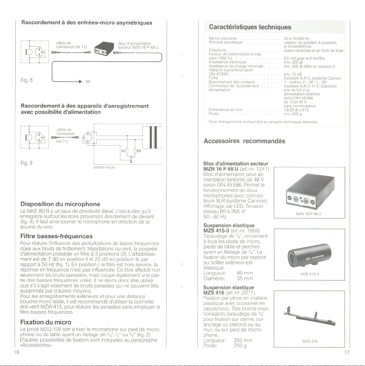
Raeeordement ades entrees-miero asymetriques
r---rn
nni
:
I I
: ~:--
I ,I
I I
~
: eonnexion KA 7 U
eable de
.i@~.-
..
bloc d'al,mentat,on
secteur MZN 16 P 48 U
,
.
. )
:~'8U' c
Raeeordement ades appareils d'enregistrement
avee possibilite d'alimentation
rn-r-n-Ui -
:
I . I eonnexlon ?
: o:--~
: ': KA7U
~
Ln-Ln- n_J
: cablede
Caracteristiques techniques
Bande passante
Prinelpe aeoustique
Facteur detransmission a vlde
pour 1000 Hz ...
Impedanee eleetnque . . .
Impedance de charge minimale
Rapport slgnal/bruit selon
DIN 45590 .
Flehe. . . . .
Branehement des contaets
Conneeteur de 'accordement .
Alimentation
Dimensions en mm
POlds
Taus changements, surtout dOsau progres technlque, reserves.
50 a 15000 Hz
capteur de gradient a pression
et d'lnterterenee
super-cardio'r'deet en form de lobe
0,5 mV/l'bar '" 5 mV/Pa
env. 200 Q
env. 300 Q (filtre en position I)
env. 70 dB
tnpolaire XLR-3,systeme Cannon
1 - boiller, 2 - BF, 3 - BF
tnpolaire XLR-3-11-C (Cannon)
pile de 5,6 V ou
alimentation tantöme
selon DIN45596
de 12 et 48 V
sans commutatlon
19/22 95x 313
env. 205 g
Accessoires recommandes
I
Fig.9
entree miero
Dispositiondu microphone
Le MKE 80 Ra un taux de directivite eleve, c'est-a-dire qu'il
emegistre surtout les sons provenant directement de devant
(fig. 4). 11faut ainsi tourner le microphone en dlrection de la
source du son.
Filtre basses-frequences
Pour reduire I'influence des perturbations de basse frequences
dOes aux bruits de frottement, trepidations ou vent, la poignee
d'alimentation possede un filtre a 3 positions (3). L'affaiblisse-
ment est de 7 dB en position 11et 20 dB en position 111,par
rapport a 50 Hz (fig. 1). En position I, le filtre est hors service, la
reponse en frequence n'est pas influencee. Ce filtre affaiblit non
seulement les bruits parasItes, mais coupe egalement une par-
tie des basses frequences utiles. 11ne devra donc etre utilise
que s'il s'agit vraiement de bruits parasites qui ne peuvent etre
supprimes par d'autres moyens.
Pour les emegistrements exterieurs et pour une distance
bouche-mlcro faible, il est recommande d'utiliser la bonnette
anti-vent MZW 415, pour reduire les parasites sans employer le
filtre basses frequences.
Fixation du micro
La pince MZO 100 sert a fixer le mlcrophone sur pled de micro-
phone ou de table ayant un filetage de %", Y/ ou o/g"(fig. 2).
D'autres possibilites de fixation sont tndiquees au paragraphe
«Accessoires».
16
Bloc d'alimentation secteur
MZN 16 P 48 U (art.-m. 1241)
Bloc d'alimentaion pour ali-
mentation fantöme de 48 V
selon DIN 45596. Permet le
fonctionnement de deux
mlcrophones avec connec-
teurs XLR (systeme Cannon).
Afflchage par LED. Tension
reseau 85 a 265 VI
50-60 Hz.
Suspension elastique
MZS 415-3 (art.-m. 1956)
Taraudage de %", convenant
a tous les pleds de mlcro,
pleds de table et perches
ayant un filetage de %". La
fixation du micro par rapport
au bOItier exterieur est
elastique.
Longueur:
DIametre:
Suspension elastique
MZS 416 (art.-m. 2071)
Fixation par pince en matlere
plastique avec cousslnet en
caoutchouc. Tres bonne inso-
norisatlon, taraudage de %"
pour fixation sur canne, sur
ancrage ou plafond ou au
mur, ou sur pied de micro-
phone.
Longueur:
Poids:
80 mm
35 mm
350 mm
250 9
MZN16P48U
MZS415-3
~
MZS416
17
Page 11

MZG415-3
MZB415
Articulation MZG 415-3
(alt-nr, 1955)
Elle sert, avec la suspension
elastique MZS 415-3 a la fixa-
tion des microphones sur
pied de microphone ou de
table, Grace a un filetage
interchangeable, convient aux
filetages %", %" ou Y/,
Privotesur 1800.
Couleur: nOlre,
Canne de microphone
MZB415 (art,-nr, 0972)
Canne en fibre de verre en
deux parties, Fixation du
microphone avec angle
d'inclinalson reglable et
filetage de %", Direction
d'enregistrement se regle en
toumant la canne de 3600.,
Longueur: repliee 120 cm
Poids:
Pieds de table MZT 100
(art,-nr, 1883)
Pled de table robuste, entoure
de mousse, tres grande stab i-
lite et bonne insonorisation,
Vis de fixation %",
etiree 340 cm
env, 640 9
MZT441
r ,
tO Qt
L ~
XLR-3-11 C XLR-3-12 C
3 3 I
~
I , I
l______-------------------
XLR-3-11 C T 3260001
18
Pied de table
(art,-nr, 0799)
Pied de table metallique,
robuste et stable, avec VIS%",
Convenant
Couleur: grise,
Cördon de raccordement
KA7 U (art,-nr, 1777)
Cordon de raccordement
entre microphone a fiche tri-
polaire XLR-3 systeme Can-
non et entrees-micro symetri-
ques avec borne tripolaire
MZT441
a MZG415-3,
XLR,systeme Cannon,
Longueur: 7,5 m
Cordon de raccordement
KA 7 UN (art,-nr, 2157)
Cordon de raccordement
entre microphones a fiche tri-
polaire XLR-3, systeme Can-
non et entrees-micro a borne
tripolaire vissante selon
DIN 41 524,
Longueur: 7,5 m
 Loading...