

Specifications and Main Features
- Microphones: MKE 203, MKE 403, MKE 803, MKE 883
- Powering Modules: K 3 N and K 3-U
- Suitable Battery Type: Mercury battery 5.6 V (e.g. Mallory PX 23, Varta 23 PX, Ucar EPX 23)
- Operating Time: Over 600 h
- Frequency Response: 50...15,000 Hz
- Acoustic Operation: Pressure transducer (MKE 203 and MKE 403), Pressure-gradient interference transducer (MKE 803, MKE 883)
- Directional Characteristics:
- MKE 203: Omnidirectional
- MKE 403: Supercardioid
- MKE 803: Supercardioid/lobe
- MKE 883: Cardioid/lobe
- Output Impedance: Around 200 Ohms
- Minimum Load Impedance: 300 Ohms (switch position I)
- Recommended Load Impedance: >5k Ohms (switch positions II and III).
- Bass Cut Filter: Switchable (included with K 3 N and K 3-U).
- Signal-to-Noise Ratio: About 64 dB to 70 dB.
- Connector Type:
- K 3 N: 3-pin DIN connector according to DIN 41524
- K 3-U: 3-pin Cannon XLR-3 connector
- Dimensions:
- MKE 203: 19/22 @ x 186 mm, Weight: About 160 g.
- MKE 403: 19/22 @ x 186 mm, Weight: About 160 g.
- MKE 803: 19/22 @ x 298 mm, Weight: About 195 g.
- MKE 883: 19/40 @ x 688 mm, Weight: Approximately or exactly:135 g
- Flea accessories: MZT 104 desk stand, MZT 105-1 desk stand, MZW 30 and MZW 415 windshields, MZA 406 microphone clamp, MZG 802 camera-microphone holder, MZS 802 special telescope and connection cables.
Frequently Asked Questions
- Q: What power supply operates MKE 203, MKE 403, MKE 803, and MKE 883?
A: The microphones can work with a mercury battery of 5.6 V or be phantom powered by external supplies giving 12…48 V.
- Q: How long would the battery be for during operation?
A: The battery lasts for over 600 hours of operation.
- Q: Are different microphone heads with one powering module usable?
A: Yes, the modular design enables mic heads to be fitted to appropriate powered modules.
- Q: What are the directional characteristics of the microphones?
A:
- MKE 203: omnidirectional characteristic.
- MKE 403: supercardioid characteristic..
- MKE 803: supercardioid and lobe characteristic.
- MKE 883: cardioid and lobe characteristic.
- Q: What steps do I take to determine the microphone’s battery voltage?
A: When the microphone is turned either on or off, the battery voltage can be checked and a light emitting diode will blink if the voltage is reasonable.
- Q: Which specific battery, for a microphone, do I need to acquire?
A: A 5.6 V mercury battery, including Mallory PX 23, Varta 23 PX or Ucar EPX 23, is required by the microphone.
User Manual
Page 1
Page 2
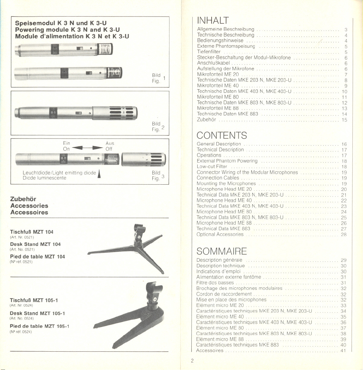
Speisemodul K 3 N und K 3-U
Powering module K 3 N and K 3-U
Module d'alimentation K 3 N et K 3-U
Leuchtdiode/Light emitting diode.
Diode luminescente
Zubehör
Accessories
Accessoires
Tischfuß MZT 104
(Art Nr.0521)
Desk Stand MZT 104
(Art.No.0521)
Pied de table MZT 104
(N°rel.0521)
Tischfuß MZT 105-1
(Art. Ne. 0524)
Desk Stand MZT 105-1
(Art.No.0524)
Pied de table MZT 105-1
(N°rel.0524)
Bild 1
Fig.
Bild
Fig.2
Bild
Fig.3
INHALT
Allgemeine Beschreibung
Technische Beschreibung
Bedienungshinweise. . . . .
Externe Phantomspeisung
Tiefenfilter. . . . . .. . .. ......
Stecker-Beschaltung der Modul-Mikrofone
Anschlußkabel. . .. .. ...
Aufstellung der Mikrofone
Mikrofonteil ME 20 .
Technische Daten MKE 203 N, MKE 203-U .
Mikrofonteil ME 40. . . . . . .. .....
Technische Daten MKE 403 N, MKE 403-U
Mikrofonteil ME 80 .......
Technische Daten MKE 803 N, MKE 803-U .
Mikrofonteil ME 88 ........
Technische Daten MKE 883
Zubehör
CONTENTS
General Description .
Technical Description
Operations. . . . . . . . . .. . . .
External Phantom Powering
Low-cut Filter. . . . . . . . . . . . . . . . . . . . . . .. .
Connector Wiring of the Modular Microphones
Connection Cables . . . . . . .
Mounting the Microphones
Microphone Head ME 20 .. . .......
Technical Data MKE 203 N, MKE 203-U
Microphone Head ME 40 . . . . . . . . . . . . . .
Technical Data MKE 403 N, MKE 403-U .
Microphone Head ME 80 .. . .
Technical Data MKE 803 N, MKE 803-U .
Microphone Head ME 88 .
Technical Data MKE 883
Optional Accessories
SOMMAIRE
Description generale.
Description technique
Indications d'emploi ........
Alimentation externe fantöme
Filtre des basses. ..............
Brochage des microphones modulaires
Cordon de raccordement . .. .
Mise en place des microphones
Element micro ME 20.. . ..
Caracteristiques techniques MKE 203 N, MKE 203-U
Element micro ME 40 . . . . . . . . . . . . . .. ...
Caracteristiques techniques MKE 403 N, MKE 403-U
Element micro ME 80 . . . .. . ........
Caracteristiques techniques MKE 803 N, MKE 803-U
Element micro ME 88 . . . . .. . . .. . . . . .
Caracteristiques techniques MKE 883
Accessoires.
2
3
4
4
5
5
6
6
6
7
8
9
10
11
12
13
14
15
16
17
17
18
18
19
19
19
20
21
22
23
24
25
26
27
28
29
30
30
31
31
32
32
32
33
34
35
36
37
38
39
40
41
Page 3
MKE 203, MKE 403, MKE 803,
MKE 883
BEDIENUNGSANLEITUNG
Allgemeine Beschreibung
Die Elektret-Kondensator-Mikrofone MKE 203, MKE 403, MKE 803
und MKE 883 bilden ein Modulsystem. Jedes Mikrofon dieser Typen-
reihe besteht aus einem Griffteil und einem MIkrofonkopf. Jedes
Griffteil kann wahlweise mit den verschiedenen Mikrofonköpfen,
kombiniert werden
Dieses System macht es daher möglich, zunächst den gewünsch-
ten Grundtyp zu erwerben und bei Bedarf die weiteren Mikrofon-
köpfe einzeln nachzubestellen. Das Griffteil bildet das Speiseteil des
Mikrofons und kann mit einer Batterie versehen werden oder aus
Studio-Stromversorgungen für Phantomspeisung fremdgespeist
werden.
Folgende Mikrofone entstehen durch die Kombination von Speise-
modul und Mikrofonkopf:
MKE 203 = Speisemodul K 3 + Kugelkopf ME 20
MKE 403 = Speisemodul K 3 + Supernierenkopf ME 40
MKE803 = SpeisemodulK3 + RichtrohrkopfME80
MKE 883 = Speisemodul K 3 + Richtrohrkopf ME 88
Die Mikrofone erhalten zur Kennzeichnung - je nach Steckeraus-
führung des verwendeten Speisemoduls - noch die Bezeichnung
N oder -U.
Zum Lieferumfang der Griffteile gehört eine Batterie und das Gelenk
104-1 für die Montage auf TischfüBen und Stativen.
MZG
3
Page 4
Technische Beschreibung
SPEISEMODUL K 3 N UND K 3-U
Die beiden Speisemoduln sind für Batteriespeisung und Phantom-
speisung nach DIN 45596 für Speisespannungen 12. . .48 V ohne
Umschaltung ausgelegt. Die Batterie reicht für etwa 600 Betriebs-
stunden. Die Betriebsbereitschaft wird beim Einschalten des Mikro-
fons durch eine Leuchtdiode angezeigt. Die Batteriekontrolle ist mit
dem knackfreien Ein/Aus-Schalter gekoppelt und erfolgt
bei jeder Betätigung des Schalters. Bei Phantomspeisung muß
die Batterie nicht entfernt werden.
Die Speisemoduln sind mit einem Übertrager für niederohmigen
symmetrischen Betrieb ausgerüstet. Ein in zwei Stufen schaltbares
Tiefenfilter erlaubt es, den Betrieb der tiefen Frequenzen entspre-
chend den abgebildeten Kurven (Bild 5) abzusenken. Bei Belastung
mit Widerständen< 5 kf! verschiebt sich die untere Grenzfrequenz
zu höheren Frequenzen und die Tiefenabsenkung erfolgt mit einer
geringeren Steilheit.
Das Speise modul K 3 N ist mit einem dreipoligen Normstecker aus-
gerüstet und nach Schema N beschaltet. Das Speisemodul K 3-U
besitzt einen dreipoligen Cannon-Stecker und ist nach Schema -U
beschaltet.
Batterietype: Ouecksilberoxyd-Batterie 5,6 V (z. B. Mallory PX 23,
Varta 23 PX, Ucar EPX 23) (siehe Bild 1)
Bedienungshinweise
Batteriespan nungsko ntrolle
Ein Ein/Aus-Schalter ist so ausgelegt, daß beim Einschalten (rotes
Feld sichtbar) und Ausschalten des Mikrofons die zur Batteriespan-
nungskontrolle eingebaute Diode kurzzeitig hell aufleuchtet, solange
die Betriebsspannung für das Mikrofon ausreichend ist.
Wenn die Helligkeit erkennbar nachläßt, soll die Batterie gewechselt
werden. Es ist jedoch noch eine Reserve von etwa 20 Stunden vor-
handen, Zeit genug, um eine Ersatzbatterie zu besorgen. Die nor-
male Lebensdauer der Batterie beträgt etwa 600 Stunden, Ersatz-
batterien sind in Fotofachgeschäften erhältlich. Ist das Mikrofon nicht
in Gebrauch, so soll es ausgeschaltet werden, um unnötiges Ent-
laden der Batterie zu vermeiden (siehe Bild 2)
Einsetzen der Batterie
Zum Batteriewechsel wird der Mikrofonkopf abgeschraubt, das Bat-
teriefach ist dann frei zugänglich. Die Ouecksilberoxydbatterie* wird
wie auf dem Batteriefach-Aufkleber gezeigt, eingesetzt.
Externe Phantomspeisung
Alle Mikrofonkombinationen mit den Griffteilen K 3 N und K3-U
können mit Spannungen zwischen 12 . . . 48 V aus externen Netz-
geräten phantomgespeist werden. Der Ein/Aus-Schalter muß bei
Betrieb des Mikrofons mit Phantomspeisung in der Stellung "Ein"
bleiben, da der Schalter auch die Tonfrequenz schaltet. Die Batterie
wird jedoch in diesen Fällen nicht verbraucht. Sollte aus irgendeinem
Grunde die externe Speisung ausfallen, so bleibt das Mikrofon in
Betrieb, wenn eine Batterie eingesetzt ist.
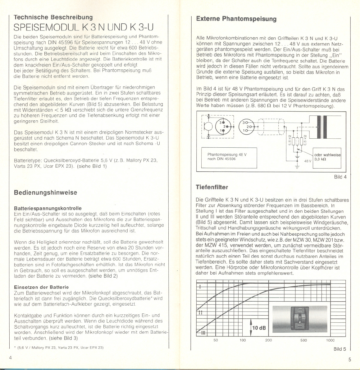
Im Bild 4 ist für 48 V Phantomspeisung und für den Griff K 3 N das
Prinzip dieser Speisungsart erläutert. Es ist darauf zu achten, daß
bei Betrieb mit anderen Spannungen die Speisewiderstände andere
Werte haben müssen (z. B. 680 f! bei 12 V Phantomspeisung).
--"-------
i
I -,
I 3 :
: 2
~
: 1 I
c_+ I
Phantomspeisung 48 V
nach DIN 45596
"
- 48V I 3,3 kn
-l-
[
oder wahlweise
Bild 4
Tiefenfilter
Die Griffteile K 3 N und K 3-U besitzen ein in drei Stufen schaltbares
Filter zur Absenkung störender Frequenzen im Bassbereich. In
Stellung I ist das Filter ausgeschaltet und in den bei den Stellungen
'I und 11'werden Störanteile entsprechend den abgebildeten Kurven
(Bild 5) abgesenkt. Damit lassen sich beispielsweise Windgeräusche,
Trittschall und Handhabungsgeräusche wirkungsvoll unterdrücken.
Bei Aufnahmen im Freien und auch bei Nahbesprechung sollte jedoch
stets ein geeigneter Windschutz, wie z.B. der MZW 30, MZW 201 bzw.
der MZW 415, verwendet werden, um zunächst vermeidbare Stör-
anteile auszuschließen. Das eingeschaltete Tiefenfilter beschneidet
natürlich auch einen Teil des sonst durchaus nutzbaren Anteiles im
Tiefenbereich. Es sollte daher stets mit Sachverstand eingesetzt
werden. Eine Hörprobe oder Mikrofonkontrolle über Kopfhörer ist
daher bei Aufnahmen stets empfehlenswert.
Kontaktgabe und Funktion können durch ein kurzzeitiges Ein- und
Ausschalten überprüft werden. Wenn die Leuchtdiode während des
Schaltvorgangs kurz aufleuchtet, ist die Batterie richtig eingesetzt
worden. Anschließend wird der Mikrofonkopf wieder mit dem Batterie-
teil verbunden. (siehe Bild 3)
. (5,6 V / Mallory PX 23. Varta 23 PX,Ucar EPX 23)
4
50
100
200
500 1000
Bild 5
5
Page 5
Stecker-Beschaltung der Modul-Mikrofone
Schaltschema N
Stecker. . . 3poliger Normstecker
nach DIN 41524 . Beschaltung
Stift ITonfrequenzI BeiexternerSpeisung
1:
NF(+)
2:
Masse,
Gehäuse
3:
NF(-)
nachDIN45596
Speisung(+)
Speisung(-)
Speisung (+)
- Masse
Schaltschema -U
Stecker. . . 3poliger Cannon-
Stecker XLR-3 . Beschaltung
Stift ITonfrequenz I Bei externer
1:
Masse,
Gehäuse
2:
NF (+)
3:
NF(-)
Phantomspeisung
Speisung (-)
Speisung (+)
Speisung (+)
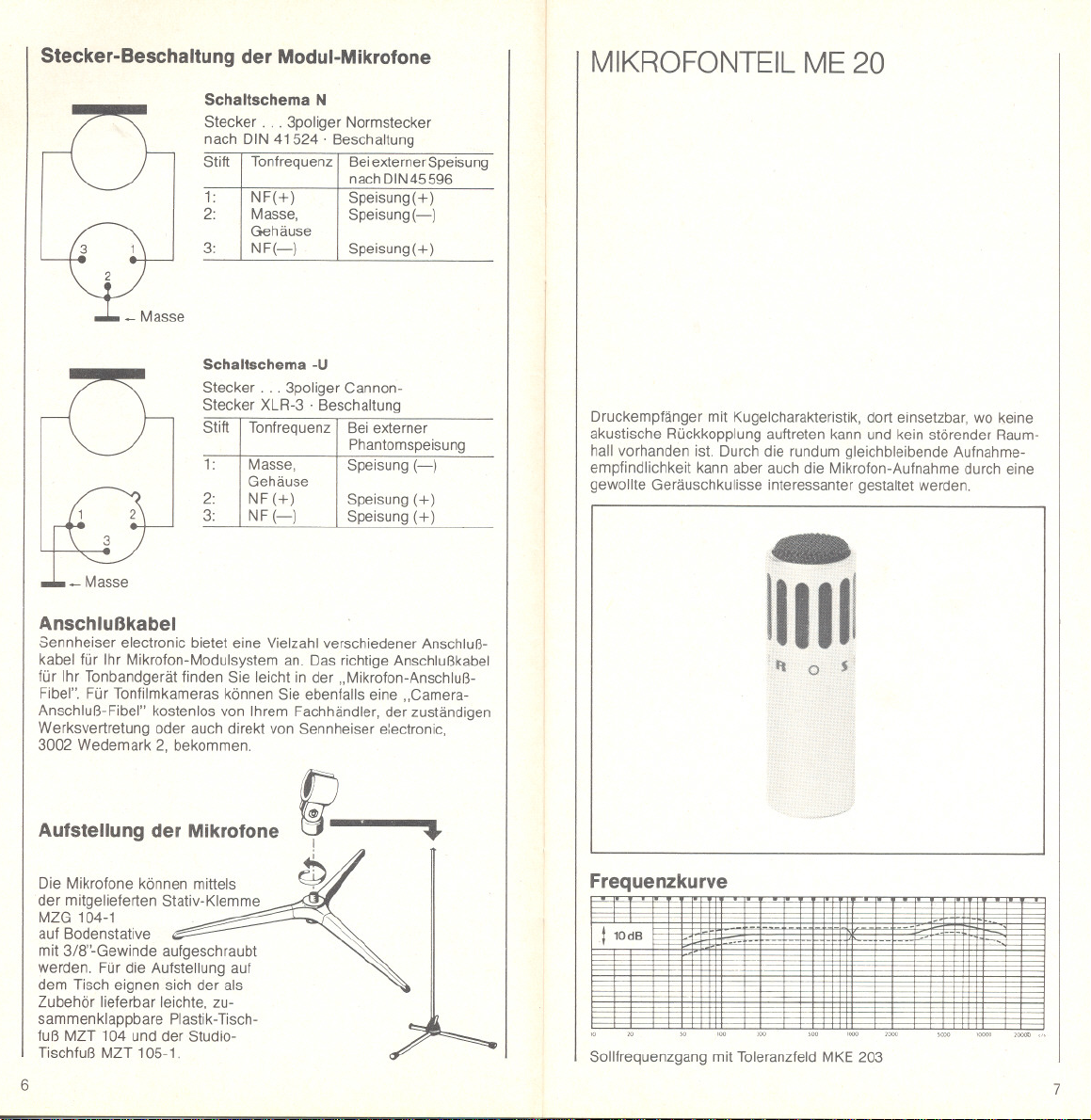
MIKROFONTEIL ME 20
Druckempfänger mit Kugelcharakteristik, dort einsetzbar, wo keine
akustische Rückkopplung auftreten kann und kein störender Raum-
hall vorhanden ist. Durch die rundum gleichbleibende Aufnahme-
empfindlichkeit kann aber auch die Mikrofon-Aufnahme durch eine
gewollte Geräuschkulisse interessanter gestaltet werden.
Anschlußkabel
Sennheiser electronic bietet eine Vielzahl verschiedener Anschluß-
kabel für Ihr Mikrofon-Modulsystem an. Das richtige Anschlußkabel
für Ihr Tonbandgerät finden Sie leicht in der "Mikrofon-Anschluß-
Fibel". Für Tonfilmkameras können Sie ebenfalls eine "Camera-
Anschluß-Fibel" kostenlos von Ihrem Fachhändler, der zuständigen
Werksvertretung oder auch direkt von Sennheiser electronic,
3002 Wedemark 2, bekommen.
Aufstellung der Mikrofone
Die Mikrofone können mittels
der mitgelieferten Stativ-Klemme
MZG 104-1
auf Bodenstative
mit 3/8"-Gewinde aufgeschraubt
werden. Fürdie Aufstellung auf
dem Tisch eignen sich der als
Zubehör lieferbar leichte, zu-
sammenklappbare Plastik-Tisch-
fuß MZT 104 und der Studio-
Tischfuß MZT 105-1.
6
fit.
~
Frequenzkurve
- - - - ---
- - -
110dS
Sollfrequenzgang mit Toleranzfeld MKE 203
-' --
- -
'
"
-
7
Page 6

Übertragungsbereich
Akustische Arbeitsweise
Richtcharakterlstik
Feld-Leerlaut-Übertragungs-
faktor bel 1000 Hz
Elektrische Impedanz
Minimale Abschlußimpedanz
Emptohlene
Abschlußimpedanz
Baßschalter
Geräuschspannungsabstand
nach DIN 45590
Stecker
Steckerbeschaltung
Anschlußkupplung
Stromversorgung
Betriebszeit der Batterie
Abmessungen In mm
Gewicht. . .
Obertläche
MKE 203 N
(K 3 N + ME 20)
50 15000 Hz
Druckemptänger
Kugel
0,3 mV/JLbar'" 3 mV/Pa 0,3 mV/JLbar'" 3 mV/Pa
:t 2,5 dB :t 2,5 dB
ca. 200 n ca.200 n
300 n (SchaltersteIlung I) 300 n (SchaltersteilungI)
>5kn >5kn
(SchaltersteIlungen11) (Schaltersteilungen11)
und 111) und 111)
siehe Technische Beschreibung K 3 N
ca. 64 dB
3 poliger verschraubbarer
Normstecker
nach DIN 41524
1~ NF,2~ Gehäuse,
3
~ NFnachDIN45594
3polige verschraubbare
nach DIN 41524,
z.B. T 3261001
5,6 V Batteriespeisung
oder Phantomspeisung
nach DIN 45596 tür
12. 48 V
ohne Umschaltung
mehr als600 Stunden
19/220 x 186
ca. 160 9
Satinnickel
MKE 203.U
(K3-U + ME20)
50.. 15000 Hz
Druckemptänger
Kugel
ca.64 dB
3poliger CannonXLR-3
1~ Gehäuse,
2~ NF, 3~ NF
3polige Cannonkupplung
XLR-3-11 C
5,6V Batteriespeisung
oder Phantomspeisung
nach DIN 45596 für
12...48 V
ohne Umschaltung
mehrals 600 Stunden
19/220 x 201
ca. 1709
Sabnnickel
MIKROFONTEIL ME 40
Mit Supercardioide-Richtcharakteristik. Vielseitig einsetzbar: In
akustisch ungünstiger und zur Rückkopplung neigender Umgebung,
bei starken Umweltgeräuschen und Raumhall. Bei günstiger Mikro-
fonaufstellung, etwa so, daß Störschall von schräg hinten auf das
Mikrofon auftrifft, kann Umgebungslärm wesentlich geringer aufge-
nommen werden.
0'
Änderungen, vor allem zum technischen Fortschritt, vorbehalten.
8
90'
180' 180'
250H,
_nn_-. . -- .'-
n n.
Frequenzkurve
110dB
-
_"'OOH,
n_n__- 4oooH, . 8oooH,
"
"- -- n - -
"
e-
Sollfrequenzgang mit Toleranzfeld MKE 403
- 5OOH,
n- 2oooH,
-
'"
--
90'
9
Page 7
MIKROFONTEIL ME 80
MKE 403 N
(K 3 N + ME 40)
Obertragungsbereich ...
Akustische Arbeitsweise
Richtcharakteristik . .
Feld-Leerlauf-Obertragungs-
faktor bei 1000 Hz
Elektrische Impedanz. .. ... ca. 20011 ca.20011
Minimale Abschlußimpedanz 30011 (SchaltersteilungI) 30011(SchaltersteilungI)
Empfohlene
Abschlußimpedanz >5k11 , >5k11
Baßschalter. . siehe Technische Beschreibung K 3 N
Geräuschspannungsabstand
nach DIN 45590
Stecker
Steckerbeschaltung.
Anschlußkupplung
Stromversorgung
Betriebszeit der Batterie.
Abmessungen inmm
Gewicht.
Oberfläche
50. 15000 Hz 50...15 0001-lz
DruckgradientenempfängerDruckgradientenempfänger
Superniere Superniere
0,3 mV/lLbar~ 3 mV/Pa 0,3 mV/lLbar~ 3 mVlPa
:t 2,5 dB :t 2,5 dB
(SchaltersteIlungen11 (SchaltersteIlungenII
und 111) und 111)
ca. 64 dB
3poliger verschraubbarer
Normstecker nach
DIN 41524
1 NF,2 Gehäuse,
3 NFnach DIN 45594
3polige verschraubbare
Normkupplung nach
DIN41524, z.B.
T 3261001
5,ß V Batteriespeisung
oder Phantomspeisung
nach DIN 45596 für
12...48 V
ohne Umschaltung
mehr als 600 Stunden
19/220 x 186
ca. 160 9
Satinnickel
MKE 403-U
(K3-U + ME40)
ca. 64 dB
3poliger CannonXLR-3
1 Gehäuse,
2 NF,3 NF
3polige Cannonkupplung
XLR-3-11 C
5,6 V Batteriespeisung
oder Phantomspeisung
nach DIN 45596 tür
12. 48 V
ohne Umschaltung
mehrals 600 Stunden
19/220 x 201
ca. 1709
Satinnickel
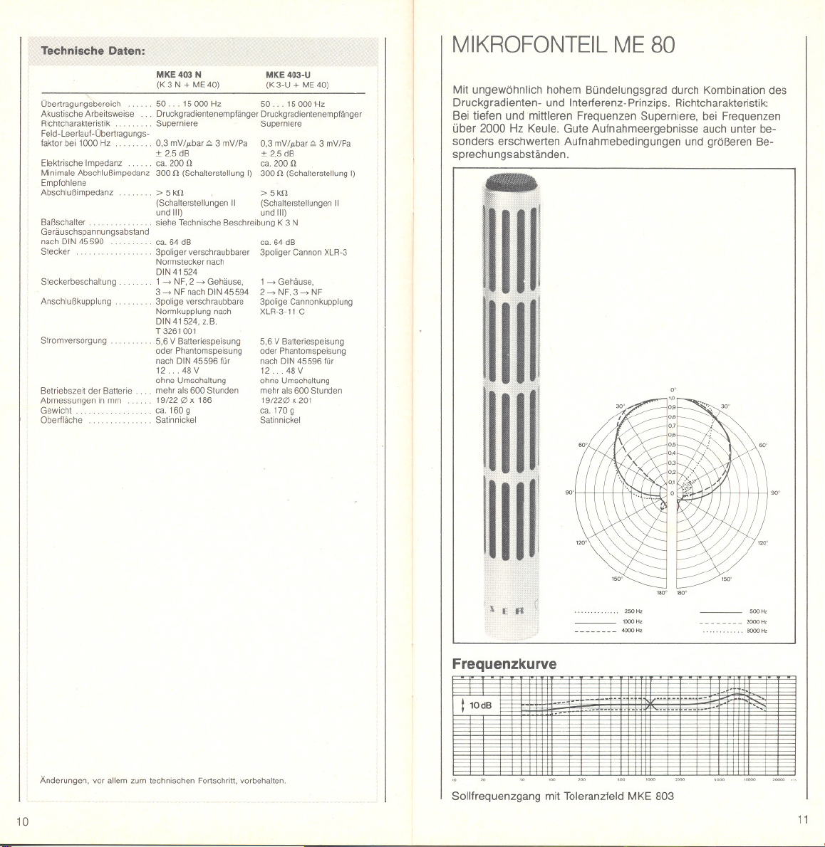
Mit ungewöhnlich hohem Bündelungsgrad durch Kombination des
Druckgradienten- und Interferenz-Prinzips. Richtcharakteristik:
Bei tiefen und mittleren Frequenzen Superniere, bei Frequenzen
über 2000 Hz Keule. Gute Aufnahmeergebnisse auch unter be-
sonders erschwerten Aufnahmebedingungen und größeren Be-
sprechungsabständen.
Änderungen, vor allem zum technischen Fortschritt, vorbehalten.
10
90'
18O' 18O'
- 1OOOH,
nu
4oooH,
Frequenzkurve
---
---
- - -
- --
-- -- ----
110dS
-
--
Sollfrequenzgang mit Toleranzfeld MKE 803
'50'
_5OOH,
n U - n - 2000 H,
---
. 8OOOH,
11
Page 8

MKE 803 N
(K 3 N + ME 80)
Übertragungsbereich
Akustische Arbeitsweise
Richtcharakteristik . Superniere/Keule
Feld-Lee rlauf -Übertragungs-
faktor bei 1000 Hz
Elektrische Impedanz. ... ca. 200 n ca. 200 n
Minimale Abschlußimpedanz 300 n (SchaltersteIlung I) 300 n (SchaltersteIlungI)
Empfohlene
Abschlußimpedanz
Baßschalter. .. .. . siehe TechnischeBeschreibung K 3 N
Geräuschspannungsabstand
nach DIN 45590
Stecker
Steckerbeschaltung
Anschlußkupplung
Stromversorgung
Betriebszeit der Batterie
Abmessungen inmm
Gewicht
Oberfläche
50..15000Hz
Druckgradienten-
Interferenzempfänger
0,5 mV/JLbar"" 5 mV/Pa 0,5 mV/JLbar"" 5 mV/Pa
:t 2,5 dB :t 2,5dB
>5kn >5kn
(SchaltersteIlungen11 (SchaltersteIlungen11
und 111) und 111)
ca. 70 dB
3poliger verschraubbarer
Normstecker nach
DIN 41524
1-> NF,2-> Gehäuse,
3 -> NF nach DIN 45594
3polige verschraubbare
Normkupplung nach
DIN 41524,
z.B. T 3261001
5,6 V Batteriespeisung
oder Phantomspeisung
nach DIN 45596 für
12. 48 V
ohne Umschaltung
mehr als600 Stunden
19/220 x 298
ca. 195 9
Satinnickel
MKE 803-U
(K 3-U + ME 80)
50. . 15000 Hz
Druckgradienten-
Interferenzempfänger
Superniere/Keule
ca. 70 dB
3poliger CannonXLR-3
1 -> Gehäuse, 2 -> NF,
3 -> NF
3polige Cannon-Kupplung
XLR-3-11 C
5,6 V Batteriespeisung
oder Phantomspeisung
nach DIN 45596 für
12 .48 V
ohne Umschaltung
mehrals 600 Stunden
19/220 x313
ca.205 9
Satinnickel
MIKROFONTEIL ME 88
Das ME 88 ist ein extrem leichtes Richtmikrofon mit fest montiertem
Windschutz. Der ungewöhnlich hohe Bündelungsgrad entsteht durch
Verwendung eines langen Interferenzrohres, Die Kombination von
Interferenzrohr und Druckwandler ergibt zwar eine frequenzabhän-
gige Richtcharakteristik, bringt aber wesentliche Vorteile bezüglich
Windempfindlichkeit und Körperschall. In Verbindung mit dem K 3
Griff ist es besonders für Tonband- und Tonfilmamateure geeignet.
Dank seines geringen Gewichts (ca. 56 g) ist auch die Verwendung
am Teleskop MZS 802 möglich.
Änderungen, vor allem zum technischen Fortschritt, vorbehalten.
12
90" 90'
180" 180'
- 1OOOH,
nnu_- 4000",
2SO",
Frequenzkurve
-
-
-
-
10 20 so
100
Sollfrequenzgang mit Toleranzfeld MKE 883
---
--
-- --- uu m- .m-
500 20000 cl,1000 2000 5000 10000
200
- 500",
-- - n _n 2000"'
... 8000"'
-
--
--
10dBI
!!KE883
13
Page 9

MKE 883 N
(K 3 N + ME88)
Übertragungsbereich. 50 15 000 Hz
Akustische Arbeitsweise Interferenzempfänger
Richtcharakteristik Niere/Keule
FeId-Leerlaut-Übertragungs-
faktor bei 1000 Hz 5 mV/Pa", 0,5 mV//Lbar 5 mV/Pa'" 0,5 mV//Lbar
Elektrische Impedanz.
Minimale AbschlußImpedanz
Empfohlene
Abschlu8impedanz > 5 kn > 5 kn
Baßschalter
Geräuschspannungsabstand
nach DIN 45590
Stecker
Steckerbeschaltung
Anschlußkupplung
Stromversorgung
Betriebszeit der Batterie
Abmessungen In mm
Gewicht
Oberfläche
:t 2,5 dB :t 2,5 dB
200 n 200 n
300 n (SchaltersteIlungI) 300n (SchaltersteilungI)
(SchaltersteIlung11 (SchaltersteIlung11
und 111) und111)
siehe Technische Beschreibung K 3 N
> 70 dB
3poligerverschraub-
barer Normstecker
nach DIN 41524
1 , NF, 2 , Gehäuse,
3 , NF nach DIN 45594
3polige verschraubbare
Normkupplung nach
DIN41524,
z.B. T 3261001
5,6 V Batteriespeisung-
oder Phantomspeisung
nach DIN 45596 für
12 48V
ohne Umschaltung
mehrals 600 Stunden
19/400 x 688
ca.135g
Satinnickelund Alu
schwarz eloxiert
MKE 883-U
(K 3-U + ME88) Tischfuß MZT 104
50 15000 Hz
Interferenzempfänger
Niere/Keule
> 70 dB
3 poliger CannonXLR-3
1 , Gehäuse,2 , NF,
3 , NF
3polige Cannon-Kupplung
XLR-3-11 C
5,6V Batteriespeisung-
oder Phantomspeisung
nach DIN 45596 für
12 48V
ohne Umschaltung
mehrals 600 Stunden
19/400 x 703
ca. 1359
Satinnickelund Alu
schwarzeloxiert
-z.B. PX 23, EPX23, 23 PX
Änderungen, vor allem zum technischen Fortschritt,vorbehalten.
14
ZUBEHÖR
Ein leichter, zusammenklapp-
barer Plastiktischfuß. Das ab-
schraubbare Oberteil paßt auf
alle Mikrofonstative mit 3/8"-
Gewinde.
Tischfuß MZT 105-1
Stabi ler und feststehende rTisch-
fuß für den Studiobetrieb.
Nahbesprechungs-und
Windschutz MZW 30
Ovaler Schaum netz-Windschutz
passend für die Kondensator-
Mikrofone MKE 203 und
MKE 403.
Nahbesprechungs-und
Windschutz MZW 415
Dieser Schaumnetz-Windschutz
ist speziell für Kondensator-
Mikrofone wie das MKE 803
bestimmt.
Mikrofon -Klemmvorrichtu n9
MZA 406
Die Mikrofon-Klemmvorrichtung
kann alle Mikrofone bis zu
30 mm 0 aufnehmen. Sie ist
besonders praktisch für Solisten
und Bühnenkünstler, die in Form
und Größe verschiedene Mikro-
fone benutzen wollen. Mit einem
3/8"-lnnengewinde paßt sie auf
alle Stative und Ausleger.
Ka mera-M ikrofon-Ha Iterung
MZG 802
Das Gelenk MZG 802 dient zur
Montage des "Telemike" (ME 80
bzw. ME 88 + MZS 802 + K 3 N)
an Kameras, wenn diese mit einem
104" -InnengewInde versehen
sind. Die Auflagefläche des Gelen-
kes ist zum Schutze des Kamera-
gehäuses mit einem elastischen
Polster versehen. Nach Lösen
der zwischen den bei den Klemm-
stücken für den Mikrofongriff
liegenden Schraube kann die
Klemmhalterung arretierbar um
90° gedreht wieder befestigt
werden und bildet sodann einen
kleinen seitlichen Ausleger. Da-
mit kann das Telemike auch an
Kameras angebracht werden, bei
denen das Gewinde z. B. hinter
dem Griff vorgesehen ist.
Spezial-Teleskop MZS 802
Das Spezial-Teleskop MZS 802
ist für die Sennheiser-Elektret-
Kondensator-Mikrofone in Modul-
technik entwickelt. Das Doppel-
teleskop kann von etwa 23 cm
bis auf ca. 68 cm ausgezogen
werden. Es verbindet die Mikro-
fonköpfe ME 20-40-80-88 mit dem
Speiseteil K 3. Die erreichbare
Gesamtlänge beträgt dann z.B.
für ME 80
+ K 3 N etwa 1 Meter.
Die Körperschalldämmung wird
durch eine Schwinggummi-Ent-
kopplung am oberen Teleskop-
ende erreicht. Der Mikrofonkopf
kann rastbar in drei Gebrauchs-
und eine Transportposition ge-
bracht werden. Die elektrische
Verbindung erfolgt kabel los über
inneres und äußeres Teleskop.
Dieser Teleskopausleger ist so-
wohl für den Handbetrieb als'
kleine Mikrofonangel als auch
für die Anbringung an geeignete
Tonfilmkameras gedacht.
Ausführung: verchromt,
Gewicht: ca. 140 g.
Anschlußkabel MZK 802,
MZK 802-1 und MZK 802-U
Das Anschlußkabel MZK 802 und
MZK 802-1 dient zum Anschluß
des Grillteiles K 3 N an Tonfilm-
kameras mit 3,5 mm Klinken-
buchse, bzw. 3pol. Mas 30
(MZK 802-1) als Mikrofonein-
gang. Die Typenvariante MZK
802-U ist für das Grillteil K 3-U
mit Cannon-Stecker bestimmt.
Das normalerweise kurze Wende-
kabel kann bis auf 1 m Länge
ausgezogen werden.
15
Page 10

MKE 203, MKE 403, MKE 803,
MKE 833
USERS GUIDE
General Description
The electret-condenser-microphones MKE 203, MKE 403 and
MKE 803 are part 01 a modular system. Each microphone consists
01two basic parts: the powering-module and the microphone head.
All different heads can be combined with the respective powe~ng-
module. The modular system therelore provides the user with a
microphone needed to start with and the possibility to extend the
set by adding different heads which are available separately.
The powering-module is the grip 01 the microphone and can be
litted with a battery or may be phantom-powered externally lrom
studio power supplies.
The lollowing microphones are available through combination 01 a
powering-module and a head:
MKE 203 = power-module K 3 + omnidirectional head ME 20
MKE403 = power-moduleK 3 + supercardioidheadME40
MKE 803 = power-module K 3 + directional-tube head ME 80
(shotgun-type)
MKE 803 = power-module K 3 + directional-tube head ME 88
(shotgun type)
Technical Description
POWERING MODULE
K 3 N AND K 3-U
Both powering modules are designed to operate with a battery or
phantom powering according to DIN 45596 with supply voltages
lrom 12 . . . 48 V. The lile 01one battery is approxirnately 600 hours.
When switching on the microphone the battery condition is monitor-
ed by me ans 01 a light emitting diode. This battery test lunction is
combined with a clicklree ON/OFF-switch. This way the battery is
automatically tested each time this switch is operated. The battery
does not have to be removed when the powering module is operat-
ed on external phantom power supplies.
The powering modules are litted with a balancing translormer and
have a low impedance output. They incorporate a switchable low-
cut lilter. The characteristics 01this two step lilter are shown in lig. 5.
II the modules are loaded with impedances < 5 kf1 the cut-off
Irequency moves towards higher Irequencies and the attenuation
characteristic is less steep.
The powering module K 3 N is litted with a 3-pin DIN-connector
and wired according to the scheme N. The powering module K3-U
has a 3-pin XLR connector and is wired to the scheme -U
Type 01 battery: Mercury battery 5.6 V (e.g. Mallory PX 23,
Varta 23 PX, Ucar EPX 23). (see lig. 1)
Operations
Battery Voltage Check
The condition 01 the battery is checked every time the microphone
is switched on (red mark visible) or off. When switching the light
emitting diode blinks indicating sufficient supply voltage.
The microphone can be operated with one battery lor more than
600 hours. II the signal 01 the diode becomes dirn, the battery is
coming to the end 01 its usable lile. But there is still areserve 01
twenty hours left providing enough time to obtain a new battery.
New batteries are available at shops lor photo equipment. When
the microphone is not in use it should be switched off to prevent
unnecessary discharging 01 the battery. (see lig. 2)
Inserting the Battery
To change the battery the microphone head must be screwed off.
The battery compartment is then accessible. The battery, mercury
type; should be inserted as shown on the label in the cornpartment.
The microphones are designated with the code N or -U dependent
on the powering-module being used.
The powering modules are delivered complete with battery and the
swivel mount MZG 104-1 lor rnounting on table stands and tripods.
16
Proper connection and lunction are checked by switching the micro-
phone on and off. When the light ernitting diode blinks the battery
has been inserted right. The microphone head and the battery part
are now reassembled. (see lig. 3)
.(5,6 V I Mallory PX 23, Varta 23 PX,Ucar EPX 23)
17
Page 11

External Phantom Powering
All micraphone combinations with the powering modules K 3 N and
K 3 -U m~y be phantom powered with voltages between 12. . .48 V
fram extern al power supplies. The ON/OFF-switch has to remain
in the position "ON" when the microphone is phantom powered
since the switch otherwise also disconnects the audio output. The
battery, in these cases, is not used up. If for any reason the ex-
ternal power supply fails the micraphone remains in operation if a
battery has been inserted.
The principle of phantom powering for 48 V and the powering
module K 3 N is shown in figA. Pie ase note: The feed resistors have
to have different values for other voltages than 48 V (e.g. 680 f! at
12 V supply).
i~l
,"iW:
l_..:o: J
Phantom-powenng 48 V
according 10DIN 45596
Low-cut Filter
- 48V ,3.3 kf!
-.L
[
alternatively
Fig.4
Connector-wiring of the Modular Microphones
Wiring diagram N
Connector . . .3 pin male connector
to DIN 41524 . Pin connections
Pin Audio
signal
1:
Audio (+) Supply (+)
2:
Ground
3:
Audio (-) Supply (+)
Wiring diagram -U
Connector . . . male XLR-3
Pin connections
Pin Audio
signal
1:
Ground
2:
Audio (+)
3:
Audio (-) Supply (+)
Externalpower
to DIN45596
Supply (-)
Extern al power
supply
Supply (-)
Supply (+)
The powering modules K 3 N and K 3-U have a switchable low-
cut filter with three positions to attenuate interfering low frequencies.
In position 1the filter is switched off and the two positions 11and 111
attenuate low frequency interferences corresponding with the ,
characteristics shown in fig. 5. This filter thus effectively reduces
wind noise, foot steps and handling noise. When recording outdoors
and also for close miking applications a suitable wind screen e. g.
MZW 30, MZW 201 and the MZW 415 resp. should be used in
order to first of all reduce avoidable interferences. If the low-cut
filter is inserted it, of course, also attenuates part of the otherwise
use~ble low-frequency range. Filters of that type should be always
usetJ intelligently and with discretion. It is always recommended to
check your recordings e.g. with headphones during the recording
process in order to avoid disappointments.
10 dB
18
50
100
200
500 1000
Fig.5
Connection cables
Sennheiser electronic offers a multitude of different connection
cables for your modular micraphone system. The correct connection
cable for your tape recorder may be easily found in our "Mikrofon-
Anschluß-Fibel". To connect these micraphones to sound film
cameras a "Camera-Anschluß-Fibel" may be obtained through your
dealer, the Sennheiser representation in your country or directly
fram Sennheiser electronic, 3002 Wedemark 2. The booklets
mentioned are free of charge.
Mounting the Microphones
The micraphones are supplied
with a quick release clamp
~
MZG104-1. This clamp pro-
vides mounting of the micro-
phone on standard 3/8" tripod
threads. Two cable
stands are
available as optional accessor-
ies to which the clamp may be
alternatively mounted. The
MZT 104 is a light collapsable
plastic desk stand and the
MZT 105-1 is asolid metal
studio-type desk stand.
19
Page 12

MICROPHONE HEAD ME 20
Omnidirectional pressure-transducer. May be used when acoustical
feedback is not likely to occur and in rooms with little or no reverber-
ation. The omnidirectional sensitivity may on the other hand ad-
vantageously be used to pick up any acoustical environment to
make the recording livelier and more interesting.
Frequency response. . . . ..
Acoustical mode of operation
Directional characteristic
Sensitivity at 1000 Hz
Output impedance .. .
Minimum load impedance
Recommended load
impedance
Bass attenuator .
S/N to DIN 45590
Connector . ..
Pin connections
Cable connector
Powersupply
50... 15000 Hz
pressure transducer
omnidirectional
0.3 mV/"bar ,G;3 mV/Pa
:t 2.5dB
appx. 200!1
300!1 (switch position I)
>5kf1 >5k!1
(switch positions 11and111) (switchpositions 11and 111)
see "Technical Description K 3 N"
appx. 64 dB appx.64 dB
3-pin, DIN41 524 3-pin Cannon XLR-3
1-. audio,2 -. housing/ 1-. housing/ground,
ground, 3-.audio to 2 -.audio,
DIN 45594 3-.audio
3-pin, DIN41 524 3-pin Cannon
(e.g. T 3261001) (e.g. XLR-3-11 C)
5.6 V battery powering 5.6 V battery powering
or phantom powering to or phantompoweringto
DIN 45596 tor DIN45596 for
12 48V, 12 .48V,
morethan 600 hours
19/220 x 186
appx. 160 9
Satin nickel
50 .. 15000 Hz
pressuretransducer
omnidirectional
0.3 mV/"bar,G; 3 mV/Pa
:t 2.5 dB
appx.200 !1
300!1 (switchposition I)
morethan 600 hours
19/220 x201
appx. 1709
Satinnickel
Frequency response
- -
- - -
110dB
Standard frequency response MKE 203
20
-- -
- ---
- -- -
-
-
--
--f--
We reserve the right to alter specifications, especially with regardto technical
improvements.
21
Page 13

MICROPHONE HEAD ME 40
Supercardioid directional pattern. This-head has multiple applicat-
ions: to be used in acoustically poor rooms to suppress reverber-
ant sound pickup and to avoid feedback from loudspeakers.
Effectively cuts out environmental noise. All sounds reaching the
microphone from the rear are effectively attenuated.
90' 90'
Frequency response. . . . . .
Acoustical mode 01operation
Directional characteristic
Sensitivity at 1000 Hz
Output impedance .. . .
Minimum load impedance
1
\
Recommended load
impedance
Bass attenuator ...
S/N to DIN 45590
Connector ....
Pin connections
Cable connector
Power suppiy
Battery operating time
Dimensions in mm
Weight
Finish
50.. .15 000Hz
pressure gradient
transducer
super cardioid
0.3 mV/lLbar,f>3 mV/Pa
:t 2.5 dB
appx. 200 n
300 n(switch positionI)
>5kfi >5kfi
(switchpositions11and 111). (switchpositions11and 111)
see "Technical DescriptionK 3 N"
appx.64 dB appx.64 dB
3-pin, DIN 41524 3-pin CannonXLR-3
1-->audio,2 --> housing/ 1-->housing/ground,
ground, 3 -->audio to 2--> aUdio,3 -->audio
DIN45594
3-pin, DIN41524
(e.g. T 3261001)
5.6 V battery powering
or phantom powering to
DIN 45596 lor
12. 48 V,
more than 600 hours
19/220 x 186
appx. 160 9
Satin nickel
50. . . 15000 Hz
pressure gradient
transducer
super cardioid
0.3 mV/ILbar ,f>3 mV/Pa
:t 2.5 dB
appx. 200 n
300 n (switch.position I)
3-pin Cannon
(e.g. XLR-3-11 C)
5.6V battery powering
or phantom poweringto
DIN45596 for
12. .48 V,
morethan 600 hours
19/220 x 201
appx. 1709
Satinnickel
_'000H,
Frequency Response
110dB
-
n- -- - - - -- -----
-
.-
- ---
-
n - - --n-
Standard frequency response MKE 403
22
4000H,
180' 180'
_500H,
--
n- 2000H,
-
. 8000H,
--
.-
1
\
We reserve the right to alter specifications, especially with regard to technical
improvements.
23
Page 14

MICROPHONE HEAD ME 80
IHighly directional through combination of the pressure-gradient and
the interference-tube principles.
The directional characteristic is cardioid at low to mid-frequencies
and narrow-beam-shaped at frequencies above 2000 Hz.
This head ensures excellent pickup even in acoustically poor en-
vironments and allows distant voice pickup.
Frequency response. . . . .
Acoustical mode of operation
Directional characteristic
Sensitivity at 1000 Hz
Output impedance .
Minimum load impedance
Recommended load
impedance
Bass attenuator ...
S/N to DIN 45590
Connector . .
Pin connections
Cable connector
Power supply
Battery operating time
Dimensions in mm
Weight
Finish
50 15000 Hz
pressure-gradient
interferencetransducer
super cardioid/lobe
0.5 mV/p.bar,Q,5mV/Pa
:t: 2.5 dB
appx.200 n
300 n (switchposition I)
>5kn >5kn
(switch positions 11and 111) (switch positions 11and 111)
see "Technical Description K 3 N"
appx. 70 dB appx. 70 dB
3-pin, DIN 41524 3-pin CannonXLR-3
1 --->audio, 2 --->housingl 1--->housing/ground,
ground, 3 --->audio to 2--->aUdio,3 --->audio
DIN45594
3-pin, DIN 41524
(e.g. T 3261001)
5.6 V battery powering
or phantom powering to
DIN 45596 for
12. .48 V,
more than 600 hours
19/220 x 298
appx. 1959
Satin nickel
50. 15000Hz
pressuregradient
interferencetransducer
super cardioid/lobe
0.5 mVIp.bar,Q,5 mVIPa
:t:2.5 dB
appx. 200 n
300 n (switch position I)
3-pin Cannon
(e.g. CannonXLR-3-11C)
5.6V battery powering
or phantompoweringto
DIN45596 tor
12 .48 V,
morethan 600 hours
19/220 x313
appx.205 9
Satinnickel
- 1oooH,
nnnn 'oooH,
Frequency Response
110dS
-f-
-
--
["
Standard frequency response MKE 803
24
- - -
--- --- - - -
1800 180'
on
-- - - --
n n _n -
-5OOH,
nnnn 2oooH,
-
f--
We reserve the right to alter specifications, especially with regard to technical
improvements.
25
Page 15

MICROPHONE HEAD ME 88
The ME 88 is an extremely lightweight directional microphone with
fixed windscreen. Highly directional characteristic is achieved by
using a long interference tube. The combination of interference tube
and pressure transducer gives a directional characteristic which is
indeed frequency-dependent but essential advantages are obtained
regarding the sensitivity to wind and handling noises In combination
with the powering module K 3 it is especially suitable for recording
and sound film amateurs. Due to its small weight (appx. 56 g) it may
also be used with the telescope MZS 802.
Frequency response
Acoustical mode ot operation
Directional characteristic
Sensitivity at 1000 Hz
Output impedance .
Minimum load impedance
Recommended load
impedance
Bass attenuator ..
S/N to DIN 45590
Connector
Pin connections
Cable connector
Power supply
Battery operating time
Dimensions in mm
Weight
Finish
MKE 883-U
(K 3-U + ME 88)
50 15000 Hz
interference transducer
cardioid/lobe
0.5 mV//Lbar~ 5 mV/Pa
:t 2.5 dB
200 n
300 n (switch position I)
5 kn 5 kn
(switch position I1and 111)(switchposition II and 111)
see "Technical DescriptionK 3 N"
> 70 dB > 70 dB
3-pin. DIN41 524 3-pin CannonXLR-3
1~ audio.2~ housing/ 1~ housmg/ground,
ground,3~ audioto 2~ audio,3~ audio
DIN 45594
3-pin, DIN 41524
(e.g. T 3261001)
5.6 V battery powering'
or phantom powering to
DIN 45596 for
12 48 V,
more than 600 hours
19/400 x 688
appx 135 9
Satin nickel and
aluminium black
anodized
50 15000 Hz
interferencetransducer
cardioid/lobe
0.5 mV//Lbar~ 5 mV/Pa
:t 2.5 dB
200 n
300 n (switch position I)
3-pin Cannon
(e.g. CannonXLR-3-11 C)
5.6V battery powerlng"
or phantom poweringto
DIN45596 for
12 48V,
morethan 600 hours
19/400 x 703
appx. 1359
Satinnickeland
aluminiumblack
anodized
.e.g. PX23, EPX 23. 23 PX
90"
-- -- --- - 4000 H,
Frequency Response
-
-
.
-
-- --
10 20 50
100
Standard frequency response MKE 883
26
..-
--
200 500 1000 2000 5000 10000
250H,
1000H,
180" 180"
- 5OOH,
_nhn- 2000'"
-
- -. - -
.
8000'"
10dB!
90'
!!KE883
20000 cl,
We reserve the right to alter specifications, especially with regard 10 technical
improvements.
27
Page 16

OPTIONAL ACCESSORIES
Desk Stand MZT 104
A lightweight plastic stand. The
swivel clip may be detached
and mounted on all floor stands
having a 3/8" thread.
Desk Stand MZT 105-1
A stable and unobtrUsive stand
for studio use.
Wind- and Poppscreen
MZW 30
Effectively reduces wind and
popp interferences when used
with the microphones MKE 203
and MKE 403.
Windscreen MZW 415
Effectively reduces wind noise
and popp-interferences at Glose
talking applications. To be used
with the MKE 803.
Quick Release Clamp
MZA 406
This clamp will accept all micro-
phone shaft diameters up to
30 mm. Especially suited for
stage and work and soloists.
The 3/8" thread fits all stands
or booms.
Ca me ra-M icrophone-Mount
MZG 802
The microphone mount MZG 802
serves to mount the "Telemike"
(ME 80 resp. ME 88
K 3 N) to cameras as far as
these are fitted with a 1/4"
thread. To protect the surface of
the camera housing the screw-
on surface of the mount has
been fitted with an elastic pad.
If the screw between the two
clamps is loosened the whole
bar-part may be turned by 900.
If fastened in this position it
forms a small boom-type mount.
+ MZS 802 +
28
This way the "Telemike" can
also be mounted to cameras
which have the thread e.g.
behind the grip.
Special Telescope MZS 802
The special telescope MZS 802
has been developed for the
Sennheiser electret condenser
microphone modular system.
The double telescopic rod of
normally appx. 23 cm length
can be extended to appx. 68 cm.
It links the microphone heads
ME 20-40-80-88 wlth the power
module K 3. The total length for,
e.g. ME 80
comes appx. one meter. Shock
damping is accomplished through
use of a rubber-damper at the
tip of the telescope. The micro-
phone head will rest in three
clickstop positions for use and
one position for transport. The
electrical connection is made
without cable via an inner and
outer telescopic rod. This new
module can be used either
handheld as a small boom micro-
phone or mounted on suitable
sound film cameras.
Finish: chrome-plated
Weight: appx. 140 g.
Connection cable MZK 802,
MZK 802-1 and MZK 802-U
The connection cable MZK 802
and MZK 802-1 serves to con-
nect the power module K3 N
to sound film cameras with
3.5 mm jack socket resp. 3-pin
MAS 30 (MZK 802-1) as micro-
phone input. The model MZK
802-U is suited for the power
module K 3 -U with Cannon
connector. The normally short
spiral cable can be extended up
to a length of 1 m.
+ K 3 N thus be-
MKE 203, MKE 403, MKE 803,
MKE 833
MODE D'EMPLOI
Description generale
Les mlcrophones electrostatiques a electret MKE 203, MKE 403,
MKE 803 et MKE 883 forment un systeme a modules. Chaque micro
de cette serie est compose d'un element poignee et d'un element
tete de micro Chaque element poignee peut etre combine au choix
avec les differentes tetes de micro.
Ce systeme vous donne la possibilite de vous procurer d'abord le
type de base souhaite et de completer ensuite tour a tour selon
vos besoins par les autres tiHes de micro. La poignee servant
d'alimentation, peut loger une pile ou peut etre alimente de maniere
externe par circuit fantöme par des alimentations studio.
Voici la denomination des micros en fonction de la combinaison
module d'alimentation et tete de micro:
MKE 203=
omnidirectionnelle ME 20
MKE 403=
super-cardio"ide ME 40
MKE 803
directionelle ME 80
MKE 883 = moduled'alimentationK 3 + tete adirectivite
directionnelle ME 88
Le micro est caracterise encore par la lettre N ou -U en fonction
des connecteurs du module d'alimentation utilise.
La livraison de I'element d'alimentation comprend une pile et I'arti-
culation MZG 104-1 pour le montage sur pieds de table ou pieds
de micro.
module d'alimentation K 3 + tete a directivite
module d'alimentation K 3 + tete a directivite
= module d'alimentation K 3 + tete a directivite
29 I
Page 17

Description technique
Alimentation externe fantöme
MODULE D ALIMENTATION
K 3 N ET K 3-U
Ces deux modules d'alimentation sont prevus pour des alimentations
a piles et des alimentations fantömes selon DIN45596, pour des
tensions d'alimentation de 12. . .48 V sans commutation.L'auto-
nomie de la pile est d'environ 600 heures. La mise sous tension
du micro est indiquee par une diode luminescente. Le contröle de
la pile est couple au commutateur, libre de claquements, et se fait
a chaque commutation. Dans le cas d'une alimentation
fantöme, la pile peut rester en place.
Les modules d'alimentation sont equipes d'un transformateur pour
le branchement symetrique a basse impedance. Un filtre attenua-
teur des basses, commutable en deux pas, permet d'attenuer les
basses frequences selon les diagrammes (voir fig. 5). En mettant
une charge< 5 kfl, la valeur de la frequence critique inferieure
est deplacee vers des valeurs plus grandes, avec une inclinaison
moins prononcee.
Le module d'alimentation K 3 Nest equipe d'une fiche tripolaire
normalisee et branche selon le schema N. Le module d'alimentation
K 3-U est equipe d'une fiche tripolaire Cannon et branche selon le
schema -U.
Type de batterie: pile a oxyde de mercure 5,6 V (p.ex. Mallory PX 23,
Varta 23 PX, Ucar EPX 23). (voir fig. 1)
Indications d'emploi
Contröle de la tension de la pile
Le commutateur marche-arriH est con<;u de teile fa<;on, que la ,
diode de contröle de la tension d'alimentation brille pour un court
instant aussi longtemps que la tension est suffisante, si on met en
circuit (champ rouge visible) ou hors circuit le micro.
Si la luminosite diminue de maniEne perceptible, il est conseille de
changer de pile. 11y atout de meme encore une reserve d'environ
20 heures, c.a.d. assez de temps pour se procurer une pile de
rechange. La pile permet environ 600 heures de fonctionnement;
les piles de rechange sont disponibles dans les magasins speciali-
ses photo-cinema. Si le microphone n'est pas en service, il est
preferable de le mettre hors circuit afin d'eviter toute decharge
superflue de la pile. (voir fig. 2)
Toutes les combinaisons de micro a poignee K 3 N et K3-U peu-
vent iHre alimentees par circuit fantöme avec des tensions de
12 . . . 48 V par des alimentations externes. Le commutateur
marche-arriH doit rester en position «marche»en cas d'alimentation
fantöme du micro, car le commutateur coupe en meme temps la
basse frequence. La pile ne subit pas de decharge dans ces cas.
S'il y a, pour une raison quelconque, une coupure de I'alimentation
externe, le micro reste en service s'il y a une pile d'alimentation.
La fig. 4 montre le principe de I'alimentation fantöme a48 Vavec
la poignee K 3 N. Attention! pour des tensions differentes, les
resistances d'alimentation doivent avoir des valeurs differentes
(p.ex. 680fl pour une tension fantöme se 12 V).
_.!o_- i
,- I
I 3
: 2
I 1 I
I I
~
I I
,-+--- ~ [
Alimentation fantöme 48 V
selon DIN 45596
~
ou
alternativement
I
48V 3,3 kO
Fig.4
Filtre des basses
Les alimentations K 3 N et K 3-U possMent un filtre commutable
en trois pas pour I'attenuatiori des basses. En position I, le filtre est
hors service, dans les positions I1et IIlles frequences parasites
so nt attenuees selon les courbes cl-dessous (fig. 5). Ce filtre per-
met d'attenuer efficacement les bruits de vent, de pas et de manie-
ment. Pour des prises de son a I'exterieur et a faible distance source
sonore-micro, nous vous conseilions de vous servir d'une bonnette
anti-vent appropriee comme p.ex. MZW 30, MZW 201 resp.
MZW 415, pour eviter les bruits avant tout evitables. Le filtre atte-
nue naturellement aussi une partie des basses frequences normale-
ment utilisees. Ce qui veut dire, qu'il faut utiliser ce filtre avec pre-
caution et en connaissance de cause. Un essai d'ecoute ou une
ecoute continue par casque est toujours a conseiller lors d'une
prise de son.
Mise en place de la pile
Pour changer de pile, la tete de micro est devissee, le comparti-
ment des piles est accessible. La pile a oxyde de mercure* est mise
en place comme indique sur I'etiquette dans le compartiment.
Le contact et les fonctions peuvent etre contröles par une mise en
et hors circuit de courte duree. Si la diode brille alors pendant un
court instant, la pile est logee correctement. Revisser la tete de
micro avec la partie alimentation. (voir fig. 3)
, (5,6V I MalloryPX23,Varta23 PX,UcarEPX23)
30
50
100
200
500
1000
Fig.5
31
Page 18

Brochage des microphones modulaires
Schema de branchement N
Fiche. . . tripolaire normalisee
selon DIN 41524 . Brochage
Broche Basse Encasd'alimentation
frequence externeselon
0lN45596
1:
2:
3:
BF(+)
Masse,boitier
BF(-)
Alimentation(+)
Alimentation(-)
Alimentation(+)
- Masse
Schema de branchement -U
Fiche. . . tripolaire Cannon
XLR-3 . Brachage
Basse
Brache
I
frequence
1:
Masse, boitier
2:
BF(+) Alimentation(+)
3:
BF(-) Alimentation(+)
En casd' alimentation
fantöme externe
Alimentation(-)
I
ELEMENT MICRO ME 20
Capteur de pression a directivite omnidirectionnelle. Ce module
peut etre utilise dans les locaux ou jl n'y a aucun risque de reaction
acoustique ou de reverberation perturbatrice. En outre sa sens i-
bilite uniforme et omnidirectionnelle permet de realiser des effets
interessants, par exemple des enregistrements avec un fond sonore
deliberement choisi.
Cordon de raccordement
Sennheiser electronic vous offre un grand nombre de cordons de
raccordement differents pour votre systeme a micros modulaires.
Vous trouverez facilement le cordon de raccordement correct po'ur
votre magnetophone dans la documentation «Guide de branchement
pour micros». Pour votre camera vous pouvez egalement recevoir
gratuitement la documentation «Guide de branchement pour
cameras», en vous adressant a votre specialiste Hi-Fi, au represen-
tant local ou directement a Sennheiser electranic, 0-3002 Wede-
mark 2, Rep. FM. d'Aliemagne.
Mise en place des
microphones
A I'aide de la pince MZG 104-1,
comprise dans la livraison, les
micros peuvent etre visses sur
des pieds de sol
a filet 3/8".
Pour un montage sur table, les
pieds de table MZT 104 (en
matiere plastique, leger et pliant)
et MZT 105-1 (pied de table de
stUdio) livrables en tant qu'
accessoires sont particuliere-
ment appropries.
32
(t.
1-
Courbe de reponse
- - -
110dB
-f-
Courbe de reponse de consigne avec tolerances MKE 203
-
--' --
_n -
-
-
u
-
.
--
'
-,'
"
-
-
..-
33
Page 19

ELEMENT MICRO ME 40
Bande passante. . .
Principe acoustique
Directivite ...........
Facteur de transmission
a vide a 1000 Hz
Com mutateu r des basses
Rapport signal/bruit selon
DIN45590 ...
Fiches
Sode necessaire au
branchement
50 .15000Hz
capteur de pression
omnidirectionnelle
0,3 mV/lLbar~ 3 mV/Pa
:t 2,5 dB
appx. 200 n
300n
(commutateur en pos. I)
>5kn >5kn
(commutateur en pos. 1'1 (commutateur en pos. II
et 111) et 111)
voir description technique K 3 N
appx. 64 dB
Fiche tripolaire
normalisee vissable
selon DIN 41 524
1 -> BF, 2 -> bOItier,
3 -> BFselon DIN 45594
tripolaire normalisee
vissable selon
DiN 41524, p.ex.
T 3261 001
pile 5,6 Vou alimentation
fantöme selon
DIN 45596,12. 48 V
sans commutation
plus de 600 heures
19/220 x 186
appx. 160 g
nickelee satinee
50 .. . 15000 Hz
capteur de pression
omnidirectionnelle
0,3 mV/lLbar ~ 3 mV/Pa
:t 2,5dB
appx. 200 n
300n
(commutateur en pos. I)
appx. 64 dB
Cannon tripolaire XLR-3
1 -> bo1tier, 2 -> BF,
3 -> BF
Cannon tripolaire
XLR-3-11 C
pile 5,6 V ou alimentation
fantöme selon
DIN45596,12...48 V
sans commutation
plus de 600 heures
19/220 x 201
appx. 170 9
nickelee satinee
Directivite: super-cardioide. Utilisations multiples en conditions
acoustiques defavorables (haut niveau de bruit defond, reverberation).
En choisissant un emplacement favorable pour le microphone (bruit
de font venant de derriere en biais, par exemple) le bruit de fond
incident sera reduit considerablement.
0'
90'
Modifications, surtout dans I'interetdu progres technique reservees.
34
180' 180'
_'000H,
n_n_n 4000H,
Courbe de reponse
110dB
- -
-
-
1---
--- -- -- -----
_n
n - - -- n -
- _n
-
_5OOH,
nu 2000H,
-
--
-
Courbe de reponse de consigne avec tolerances MKE 403
--
35
Page 20

Bande passante. ..
Principe acoustique
Directivite ...........
Facteurde transmission
a vide a 1000 Hz
Impedance de charge
conseillee
Commutateur des basses.. voir description technique K 3 N
Rapportsignal/bruit selon
DIN 45590
Fiches
Sode necessaireau
branchement
50. ..15000 Hz
capteurde gradient
de pression
super-cardio';de
0,3 mV/JLbar'" 3 mV/Pa
:t 2,5dB
appx.200 n
300n
(commutateuren pos. I)
>5kO >5kn
(commutateuren pos. I1 (commutateuren pos. 11
et 111) et 111)
appx.64 dB
Fichetripolaire
normalisee vissable
selon DIN 41524
1-->BF,2 -->boitier,
3 -->BF selon DIN 45594
tripolaire normalisee
vissable selon
DIN41524, p.ex.
T 3261001
pile 5,6 V ou alimentation
fantöme selon
DIN 45596,12. . .48 V
sanscommutation
plus de 600 heures
19/220 x 186
appx. 1609
nickelee satinee
50.. .15000Hz
capteurde gradient
de pression
super-cardio"ide
0,3 mV/JLbar'" 3 mV/Pa
:t 2,5dB
appx.200 n
300n
(commutateuren pos.I)
appx.64 dB
CannontripolaireXLR-3
1 --> boitier, 2 --> BF;
3 --> BF
Cannontripolaire
XLR-3-11 C
pile 5,6 V ou alimentation
fantöme selon
DIN45596, 12. . .48 V
sanscommutation
plus de 600 heures
19/220 x201
appx. 170g
nickelee satinee
ELEMENT MICRO ME 80
Taux de directivite exceptionnellement eleve par combinaison des
principes (a gradient de pression et d'interference). Micro "canon».
Directivite: super-cardio'ide aux basses et moyennes frequences,
en forme de lobe au-dessus de 2000 Hz.
Bonnes prises de son dans des conditions particulierement defa-
vorables et ades distances voix/micro assez importantes.
Modifications, surtout dans l'interE!tdu progres technique reservees.
36
90'
180' ,"0'
_"JOOH,
250H,
u_- 4000H,
_500H,
-- -- -- - - 2000H,
Courbe de reponse
110dS
-'
--
Courbe de reponse de consigne avec tolerances MKE 803
- - - ----- no.-
..-
-'-
- - -
---- ----
90'
. 8000H,
-
37
Page 21

Bande passante. ..
Principe acoustique
Directivite ...........
Facteurde transmission
avidea1000 Hz
Impedance de charge
conseillee
Commutateur des basses
Rapportsignal/bruit selon
DiN 45590
Fiches
Brochage
Socie necessaire au
branchement
Alimentation
Duree de lapile. .
Dimensions en mm
Poids ..
Surface
50. 15000 Hz
capteur de gradient
d'interference
super-cardio"ide/lobe
0,5 mV/JLbar~ 5 mV/Pa
:t 2,5dB
appx.200 a
300a
(commutateuren pos. I)
>51<{} >5ka
(commutateuren pos. I (commutateuren pos. I
et 111) et Ili)
voir description technique K 3 N
appx. 70 dB
Fichetripolaire
normaliseevissable selon
DIN 41524
1-> BF, 2-> boUier,
3 -> BFselon DIN 45594
tripolaire normalisee
vissable selon
DIN41524, p.ex.
T 3261001
pile 5,6 V ou alimentation
fantöme selon
DIN 45596,12...48 V
sans commutation
plus de 600 heures
19/220 x 298
appx. 195 g
nickelee satinee
50. . . 15000 Hz
capteurde gradient
d'interference
super-cardio'ide/lobe
0,5 mV/JLbar~ 5 mV/Pa
:t 2,5dB
appx.200 a
300a
(commutateuren pos. I)
appx.70 dB
CannontripolaireXLR-3)
1-> boitier, 2-> BF,
3 -> BF
Cannontripolaire
XLR-3-11C
pile 5,6 V ou alimentation
fantöme selon
DIN 45596, 12. .48 V
sanscommutation
plus de 600 heures
19/220 x 313
appx.205 g
nickeleesatinee
ELEMENT MICRO ME 88
Le ME 88 est un microphone directionnel extremement leger avec
bon nette anti-vent, montee a demeure. Le taux de directivite excep-
tionnellement eleve resulte de I'utilisation d'un tube a interferences
long. 11est vrai que la combinaison du tube a interferences et du
capteur de pression mene a un directivite qui depend de la fre-
quence, mais qui apporte des avantages essentiels par rapport a la
sensibilite aux bruits du vent et aux bruits d'origine mecanique. En
association avec I'element K 3 (poignee), il est particulierement
approprie pour les preneurs de son et a la sonorisation directe de
films. Grace a son poids insignifiant (env 56 g) il peut aussi etre
fixe a la perche telescopique MZS 802.
Modifications, surtout dans I'interet du prog.es technique reservees.
38
900 90'
180' 180'
250H,
nnn_- 4OOOH,
1000H,
- 5OOH,
n_nn- 2000",
Courbe de reponse
-
-
-
---
--
--- --- uu uu .----
200 20000 oh500 1000 2000 5000 10000
10 20 50
-
-
100
Courbe de reponse de cousigne avec tolerances MKE 883
-
-- - -
-
. 8000"'
KE883
10dB!
39
Page 22

MKE 883 N
(K 3N + ME 88)
Bande passante. .
Principe acoustique
Directivite ... .
Facteurde transmission
a vide a 1000 Hz
Impedanceelectrique.. ..
Impedancedechargemin.
Impedance de charge
conseillee
Commutateur des basses
Rapportsignal/bruit selon
DIN 45 590
Fiche
Socle necessaire au
branchement
Alimentation
50 ..15000 Hz
capteur
d'interferences
cardio"ide/lobe
5 mV/Pa ~ 0,5 mV/ILbar
:f 2,5dB
200n
300n
(commutateuren pos. I)
>5kn >5kn
(commutateuren pos. 11 (commutateuren pos. 11
et 111) et 111)
voir description technique K 3 N
> 70 dB
Fichetripolaire
normaliseevissable selon
DIN41 524
1~ BF,2~ boHier,
3
~ BFselonDIN45594
tripolaire normalise
vissable selon
DIN 41 524, p.ex.
T.3261 001
pile 5,6 V'ou alimentation
lantöme selon
DIN45596,12 48V
sans commutation
plus de 600 heures
19/400 x 688
env. 135 g
nickelee satinee et
Alu anodise noir
.p.ex.PX23,EPX23,23PX
Modilications, surtout dans I'interet du progres technique, reservees.
40
MKE 883-U
(K 3-U + ME88)
50.. .15000Hz
capteur
d'interferences
cardio'ide/lobe
5 mV/Pa ~ 0,5 mV/lLbar
:t 2,5 dB
200n
300n
(commutateuren pos. I)
> 70 dB
Cannontripolaire XLR-3
1~ baltier, 2 ~ BF
3~ BF
Cannon tripolaire
XLR-3-11 C
pile 5,6 V'ou alimentation
lantömeselon
DIN45 596, 12 .48 V
sanscommutation
plus de 600 heures
19/400 x 703
env. 135 g
nickeleesatinee et
Alu anodise noir
ACCESSOIRES
Pied de table MZT 104
En matiere plastique, leger et
pliant. La fixation est devissable
et peut iHre montee sur tous les
supports de micro a filet de
3/8",
Pied de table MZT 105-1
Pied de table de studio robuste
et stable,
Bonnette de proximite et
anti-vent MZW 30
En mousse acoustique speciale.
Pour les microphones electro-
statiques MKE 203 et MKE 403.
Bonnette de proximite et
anti-vent MZW 415
En mousse acoustique speciale.
Specialement pour les micro-
phones electrostatiques comme
p. ex. le MKE 803.
Pinee de miere MZA 406
Oestinee a tous les microphones
dont le diametre est inferieur a
30 mm. Particulierement prati-
que pour les artistes qui doivent
utiliser plusieurs microphones
sur scene. Taraudage:3/8".
S' adapte a tous les pieds et
perches.
Fixation-miero pour eameras
MZG 802
L'articulation MZG 802 sert a fixer
le "Telemike» (ME 80 resp. ME 88
+ MZS 802 + K 3 N) ades came-
ras a taraudage 1/4". Pour pro-
teger la camera, la surface de
support de I'articulation est
equipee d'une couche protec-
trice elastique. Apres avoir des-
serree la vis situee entre les
deux elements de serrage, cette
partie peut etre tournee de 900
et reste encliquetee dans cette
position. Resserrer la vis. Oe
cette fa<;:on,il est possible de
fixer le Telemike ades cameras
dont le taraudage se trouve
derriere la poignee.
Perehe teleseopique speeiale
MZS 802
La perche telescopique speciale
a ete developpee pour les mi-
cros modulaires a electret
Senn heiser. La longueur du
double telescope peut etre choi-
sie entre 23 et 68 cm. La perche
relie les elements micro
ME 20-40-80-88 a I'alimentation
K 3. La longueur max. atteinte
est d'environ 1 m pour le
ME 80 + K 3 N. Les bruits pa-
rasites d'origine mecanique sont
attenues par un element amor-
tisseur situe a I'extremite supe-
rieure de la perche. L'articula-
tion permet trois positions de
travail et une position de trans-
port. La connexion electrique se
fait, sans cable, par I'intermedi-
aire d'un telescope interieur et
exterieur. La perche peut servir
aussi bien de perche a main
(perche a dimensions reduites)
que de perche pour cameras
sonores appropriees
Presentation: chrome
Poids: appx. 140 g.
Cordon de raeeordement
MZK 802, MZK 802-1 et
MZK 802-U
Le cordon de raccordement
MZK 802 et MZK 802-1 relie
I'element d'alimentation K 3 N
ades cameras sonores a entree-
micro jack 3,5 mm resp. tripo-
laire Mas 30 (MZK 802-1). La
variante MZK 802-U est reser-
vee a I'element d'alimentation
K 3-U a fiche Cannon. La lon-
gueur du cable helicoldal,
normalement court, peut attein-
dre 1 m.
41
Page 23

 Loading...