

Page 1
Page 2
Allgemeine
Beschreibung:
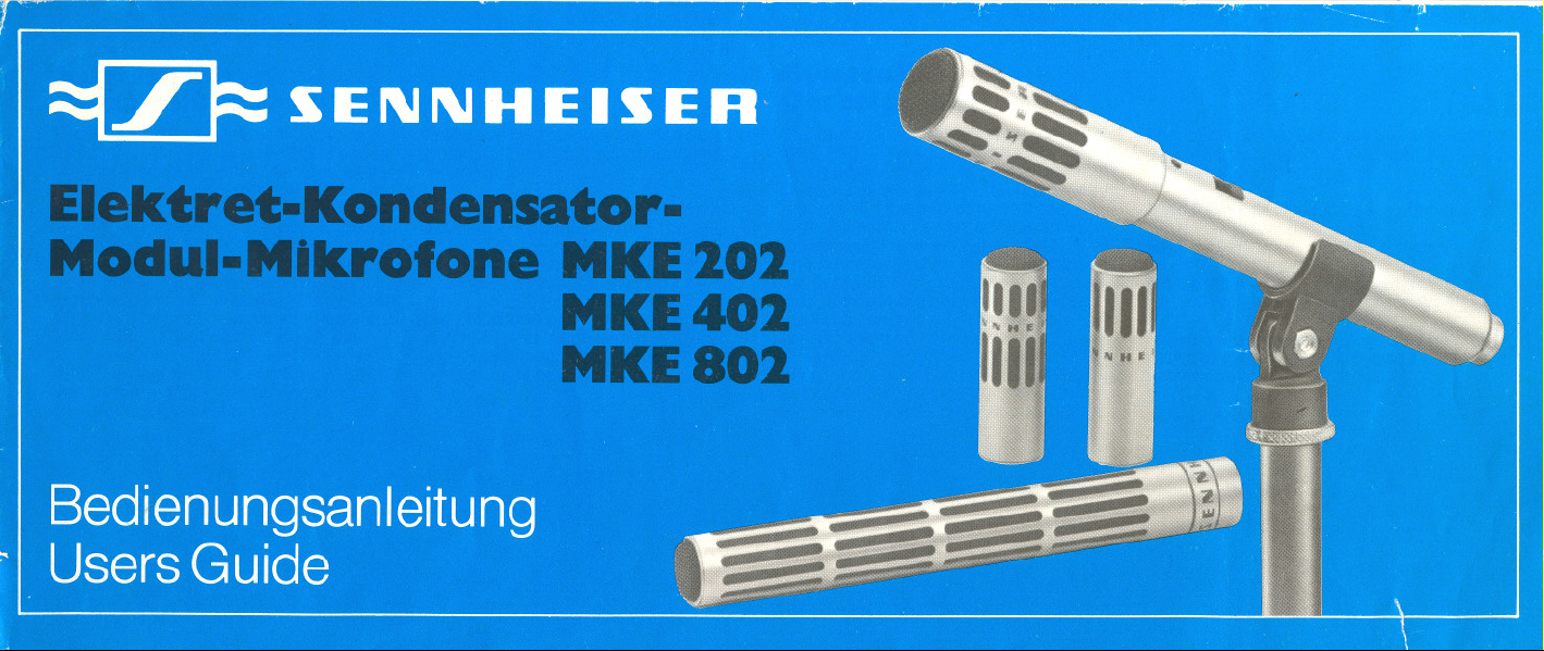
Die Elektret-Kondensator-Mikrofone
MKE 202, MKE 402 und MKE 802 bilden
ein Modulsystem. Jedes Mikrofon dieser
Typenreihe besteht aus dem Griffteil und
dem Mikrofonkopf. Jedes Griffteil kann
wahlweise mit den verschiedenen Mikro-
fonköpfen kombiniert werden.
Dieses System macht es daher möglich.
zunächst den gewünschten Grundtyp
zu erwerben und bei Bedarf die weiteren
Mikrofonköpfe einzeln nachzubestellen.
Das Griffteil bildet das Speiseteil des
Mikrofons und kann mit einer Batterie
versehen werden oder aus Studio-Strom-
versorgungen für Phantomspeisung
fremdgespeist werden.
Folgende Mikrofone entstehen durch die
Kombination von Speisemodul und
Mikrofonkopf:
MKE 202 = Speisemodul+ Kugelkopf
MKE402 = Speisemodul+ Super-
nierenkopf
MKE 802 = Speisemodul+ Richtrohr-
Kopf
Die Mikrofone erhalten zur Kennzeich-
nung - je nach Ausführung des ver-
wendeten Speisemoduls - noch die Be-
zeichnung N oder U.
General
Descrlptlon:
The electret-condenser-microphones
MKE 202, MKE 402 and MKE 802 belong
to a modular system. Each microphone
consists of two basic parts: the powering-
module and the microphone head. All
different heads can be combined with
the respective powering-module.
The modular system therefore provides
the user with a microphone needed to
start with and the possibility to extend
the set by adding different heads which
are available separately.
The powering-module is the grip of the
microphone and can be fitted with a
battery or may be phantom-powered
externally from studio power supplies.
The following microphones are available
through combination of a powering-
module and a head:
MKE 202 = power-module+ omnidi-
MKE 402 = power-module+ super-
MKE 802 = power-module+ directional-
The microphones are designated with
the code N or -U dependent on the
powering-module being used.
rectionalhead
cardioid head
tube head (shotgun type)
3
Page 3
~ -~-~ - . - .- -~- - -- ~ ~ I .
Technische
Beschrei bung:
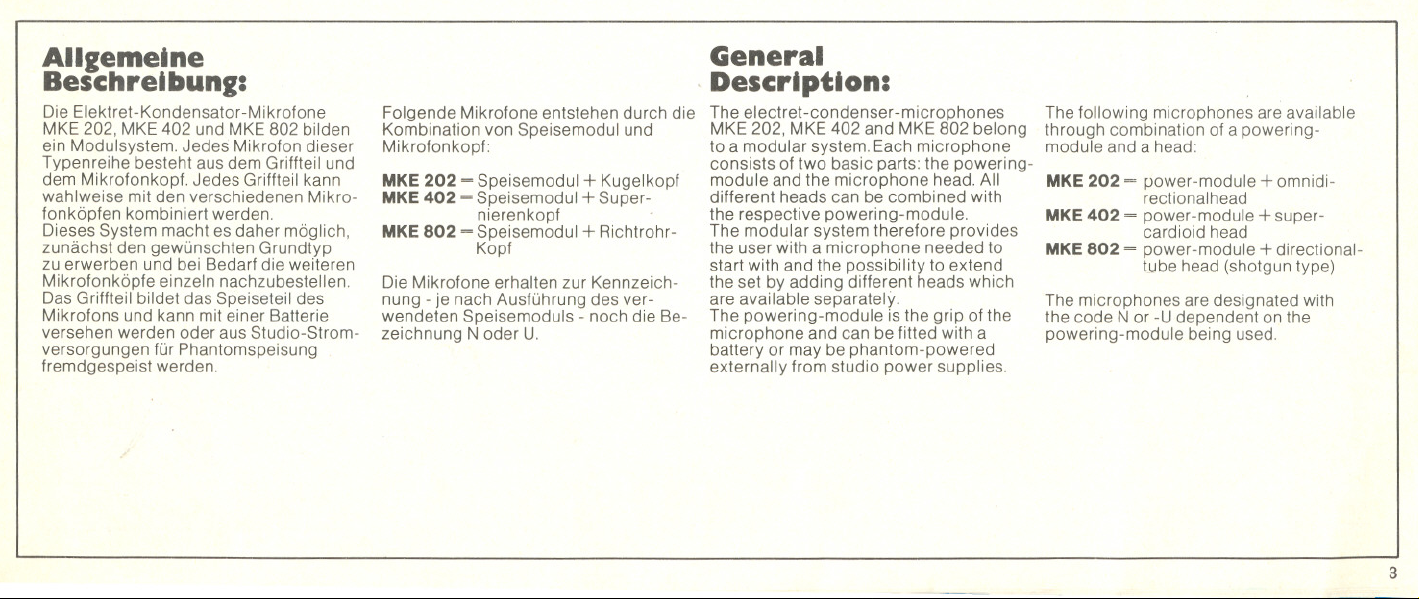
Speisemodul K 2 N und K 2-U
Die beiden Speisemodule sind mit einer
Batterie für die Stromversorgung und
einem Übertrager für niederohmigen-
symmetrischen Anschluß ausgerüstet.
Die Batterie reicht für etwa 600 Betriebs-
stunden. Die Betriebsbereitschaft wird
beim Einschalten des Mikrofons durch
eine Leuchtdiode angezeigt. Die Batterie-
kontrolle ist mit dem knackfreien Ein-
Aus-Schalter gekoppelt und erfolgt
zwangsweise bei jeder Betätigung des
Schalters. Zusätzlich kann das
Mikrofon auch an Phantomspeisungs-
Einrichtungen mit12oder 48 V
nach DIN45 596 ohne Umschaltung an-
geschlossen werden. Die Batterie muß
dabei nicht entfernt werden. Das Speise-
modul K2 N ist mit dreipoligem Norm-
stecker ausgerüstet und nach Schema
N beschaltet. Das Speise modul K2-U
besitzt einen dreipoligen Cannonstecker
und ist nach Schema Ubeschaltet.
Batterietype: Quecksi Iberoxyd-Battery
5,6 V (z.B Mallory PX 23)
4
Technical
Description:
Powering module K 2 N and K2-U
The two powering modules available
are fitted with a battery and a balancing
transfarmer for low impedance outputs.
The battery life is approximately 600
hours. When activating the on-off switch
the proper functlon is being chec-ked by
means of a light emitting diode. This
battery test is combined with a switch
for disconnecting the modulation output
of the microphone without switching
transients The microphones mayaiso
be powered on external power supplies
providing 12or 48 Vphantom feeding
according to DIN45596 without any
switching. The battery may stay in its
compartment when the extern al power is
applied.
The powering module K2 N isfitted with
a 3 pin DINconnector wired to the
scheme N.The K2-U has a XLR3 connec-
tar wired to the sc heme U.
Type of battery: Mercury-battery 5,6 V
(e g Mallory PX 23)
Speisemodul K 1 N und K 1.U
Powering module K 1 N and K 1.U
Page 4
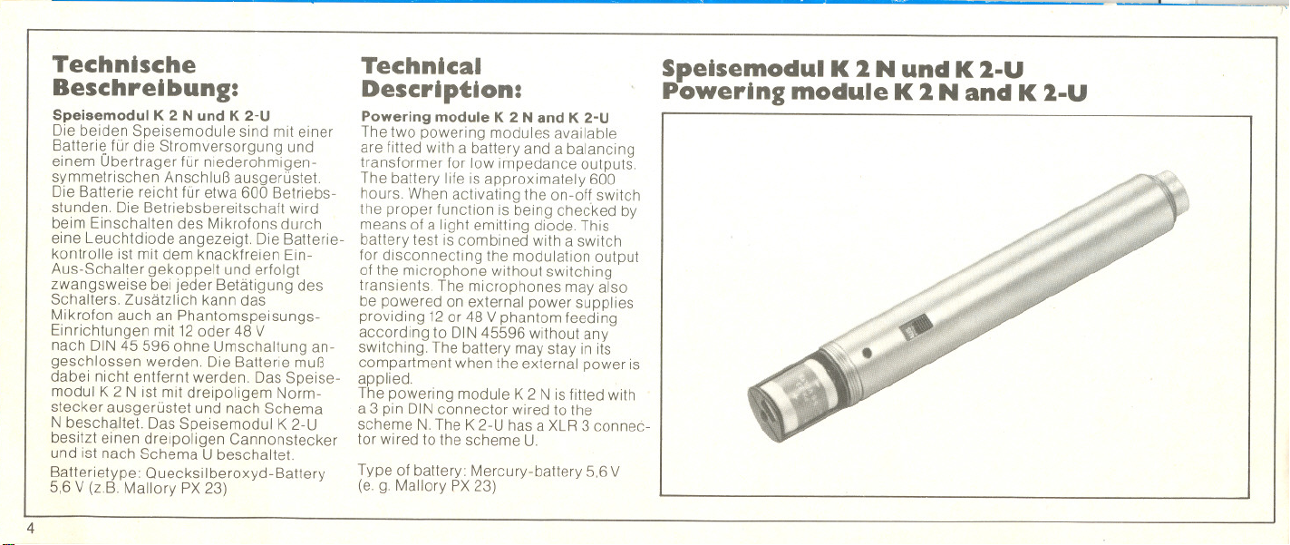
Stecker-BeSChaltun
Connector-wlrlng 0 the Modular Mlcrophones
Schaltschema N
Wiring Diagram N
der Modul-Mikrofone
f
: . 1 :
:9-CBi
I I
L_+ ~
Schaltschema-U
Wiring Diagram-U
[
3
Masse
Ground
Stecker 3poliger Normstecker
nach DIN 41524 . Beschaltung....
Siitil Tonfrequen~ Bei externer Speisung
1:
NF(+)
2:
Masse,
Gehäuse
3:
NF(-)
nach DIN 45 596
Speisung (+)
Speisung (-)
Speisung (+)
Phantomspeisung 48 V
nach DIN 45596
Phantom.powering 48 V
accordlng to DIN 45596
Connector 3 pin male connector
to DIN 41 524 . Pin connections
Pin
Audio
sianal to DIN 45 596
1:
audio (+) Supply (+)
2:
ground
3:
audio (-) Supply (+)
External power
Supply (-)
oder wahlweise
- 48 V Ialternatively
3.3 kQ
~
Stecker...3poliger Cannon-
Stecker XLR-3 . Beschaltung....
Siiii1 Tonfrequenzl Bei externer
1:
Masse,
Gehäuse
2:
NF(+)
3:
NF(-)
Phantomspeisung
Speisung (-)
Speisung (+)
Speisung (+)
Masse
Ground
Connector male XLR-3
Pin connections
Pin
Audio
signal
1: Ground.
2:
3:
Audio -
Audio i+
External power
supply
Supply (-)
Supply (+)
Supply (+)
2
5
Page 5
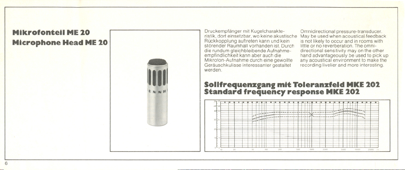
MIkrofonteIl ME20
Mlcrophone Head ME20
Druckempfänger mit Kugelcharakte-
ristik, dort einsetzbar, wo keine akustische
Rückkopplung auftreten kann und kein
störender Raumhall vorhanden ist. Durch
die rundum gleichbleibende Aufnahme-
empfindlichkeit kann aber auch die
Mikrofon-Aufnahme durch eine gewollte
Geräuschkulisse interessanter gestaltet
werden.
Omnidirectional pressure-transducer.
May be used when acoustical feedback
is not likely to occur and in rooms with
liltle or no reverberation. The omni-
directional sensitivity may on the other
hand advantageously be used to pick up
any acoustical environment to make the
recording livelier and more interesting.
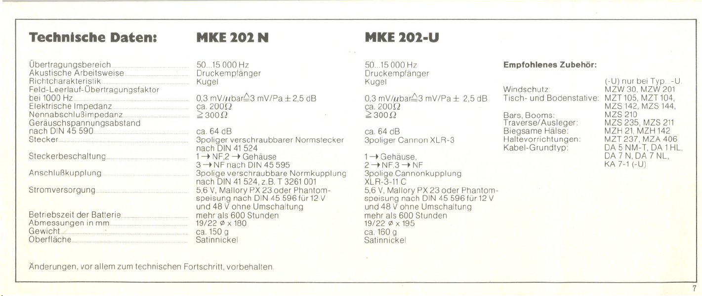
Sollfrequenzgang mit Toleranzfeld MKE202
Standard frequency response MKE202
50..25,
- -
-
30~"
20...
- -
-
.- -
-
-
---
.-
OL 0
..
6
'000
Page 6
......
Technische Daten: MKE101.UMKE 101 N
Übertragungsbereich ... .....
Akustische Arbeitsweise..
Richtcharakteristik ...
Feld -Leerlauf -Übertrag ungsfaktor
bei 1000 Hz .....
Elektrische Impedanz. ....
Nennabschlußimpedanz ... ....
Ge rä usc hs pan nun 9sabstan d
nach DIN 45
Steckerbeschaltung.
Anschlußkupplung.
Stromversorgung..
50...15000 Hz
Druckempfänger
Kugel
0,3 mVIl.tbar~3 mVIPa:!: 2,5 dB
ca. 200D
2300[2
ca. 64 dB
3poliger verschraubbarer Normstecker
nach DIN41524
1-t NF,2-~ Gehäuse
3 -~ NFnach DIN45 595
3polige verschraubbare Normkupplung
nach DIN41524, z.B.T 3261001
5,6 V,MalloryPX 23 oder Phantom-
speisung nach DIN45 596 für 12V
Betriebszeit der Batterie. .
Abmessungen in
Oberfläche....
und 48 Vohne Umschaltung
mehr als 600 Stunden
19/22 </>x 180
ca. 150 9
Satinnickel
Anderungen, vor allem zum technischen Fortschritt, vorbehalten.
50...15000 Hz
Druckempfänger
Kugel
0,3 mV/l!bar~3 mV/Pa:!: 2,5 dB
ca 200D
2 300 Q
ca. 64 dB
3poliger Cannon XLR-3
1-~ Gehäuse,
2 -t NF,3-~ NF
3polige Cannonkupplung
XLR-3-11C
5,6 V,Mallory PX23 oder Phantom-
speisung nach DIN45 596 für 12V
und 48 Vohne Umschaltung
mehr als 600 Stunden
19/22 </>x 195
ca. 160 9
Satinnickel
Empfohlenes Zubehör:
Windschutz:
Tisch- und Bodenstative:
Bars, Booms:
Traversel Ausleger:
Biegsame Hälse:
Haltevorrichtungen:
Kabel-Grundtyp:
(-U) nur bei Typ U.
MZW 30, MZW 201
MZT 105, MZT 104,
MZS 142, MZS 144,
MZS 210
MZS 235, MZS 211
MZH 21, MZH 142
MZT 237, MZA 406
DA 5 NM-T, DA 1 HL,
DA 7 N, DA 7 NL,
KA 7-1 (-U)
7
Page 7

Technlcal Data:
MKE 202 N
MKE202-U
Frequency response. ... ... m
Acoustical mode 01 operation....
Directional characteristic
Sensitivity at 1000 Hz
Output impedance
Nominal load.. ....
S/N to DIN 45 590....
ConnectoL .........
Pin connections
Cable connector..
Power supply...
Battery operating time
I
Dimensions in mm ..
Weight..
11
Finish
III1
111
II111
We reserve the right to alter specillcation, especially with
11
regard to technical improvements
11
.~ 8
50...15000 Hz
Pressure transducer
Omnidirectionel
0,3 mV/ ,ubar~3 mV/Pa::!: 2,5 dB
appx. 20M2
;;;:3000
appx. 64 dB
3 pin, DIN 41524
1audio, 2 housing/ground,
3 audio to DIN 45595
3 pin, DIN 41524 (e. g. T 3261001)
5,6 V, Mallory PX 23 or phantomleeding
to DIN 45596 lor 12V and 48 V,
seil adjusting
more than 600 hours
19/22 'l>x 180
appx. 150 g
Satin~Nickel
50...15000 Hz
Pressure transducer
Omnidirectional
0,3 mV/,ubar~3 mV/Pa::!: 2,5 dB
appx. 2000
;;;:3000
appx. 64 dB
3 pin Cannon XLR-3
1hOl,1sing/ground, 2 audio,
3 audio
3 pin Cannon (e. g. XLR-3-11 C)
5,6 V, Mallory PX 23 or phantomleeding
to DIN 45596 lor 12 Vand 48 V
seil adjusting
more than 600 hours
19/22 'l>x 195
appx. 160 g
Satin-Nickel
Recommended accessories:
Wind screen MZW 30, MZW 201
Table stands,
Tripods:
MZT 105,MZT 104,
MZS 142,MZS 144,
MZS 210,
Bars, Booms:
Goose necks:
Mounts:
Cables:
MZS 211,MZS 235
MZH 21, MZH 142
MZT 237, MZA 406
DA 5 NM-T, DA 1 HL
DA 7 N, DA 7 NL,
KA 7-1 (-U)
Page 8

MikrofonteU ME40
Microphone Head
ME40
MitSupercardioide-Richtcharakteristik. Supercardioid directional pattern.
Vielseitig einsetzbar: In akustisch ungün- This head has multiple applications:
stiger und zur Rückkopplung neigender to be used in acoustically poar raoms to
Umgebung, bei starken Umweltgeräuschen suppress reverberant sound pickup
und Raumhall. Beigünstiger Mikrofonauf- and to avoid feedback from loud-
stellung, etwa so, daß Störschall von schräg speakers. Effectively cuts out environ-
hinten auf das Mikrofonauftrifft,kann mental noise. Allsounds reaching the
Umgebungslärm wesentlich geringer auf- microphone fram the rear are effectively
._,"
genommen werden, attenuated.
Sollfrequenzgang mit Toleranzfeld MKE402
Standard frequency response MKE402
OL0
< ~~-.
+._.-
"
9
Page 9

Technische Daten:
MKE 402 N
MKE402.U
Übertragungsbereich
Akustische Arbeitsweise.
Richtcharakteristik ..
Feld-Leerlauf-Übertragungsfaktor bei
1000 Hz
Elektrische Impedanz
Nennabschlußimpedanz.
Geräu schspan nungsabstand
nach DIN45
Steckerbeschaltu ng
Anschlußkupplung
Stromversorgung
50...15000 Hz
Druckgradientenempfänger
Superniere
0,3 mV/~bar,Q3 mV/Pa:t 2,3 dB 2,5
ca. 200 [2
2:300Q
ca. 64 dB
3poliger verschraubbarer Norm-
stecker nach DIN41524
1-~ NF,2-~ Gehäuse,
3 -~ NFnach DIN45 595
3polige verschraubbare Norm-
kupplung nach DIN41524, z.B.
T 3261 001
5,6 V,Mallory PX23 oder Phantom-
speisung nach DIN45 596 für 12V
und 48 Vohne Umschaltung
Betriebszeit der Batterie
Abmessungen in mm
Gewicht
Oberfläche
mehr als 600 Stunden
19/22 C/Jx 180
ca. 150 9
Satinnickel
Anderungen, vor allem zum technischen Fortschritt, vorbehalten.
10
50...15000 Hz
Druckgradienten empfänger
Superniere
0,3 mV/llbar,Q3 mV/Pa:t 2,5 dB
ca. 200 n
2:300Q
ca. 64 dB
3poliger Cannon XLR-3
1-~ Gehäuse,
2 -~ NF,3 -~ NF
3polige Cannonkupplung
XLR-3-11C
5',6V,MalloryPX23 oder Phantom-
speisung nach DIN45 596 für 12V
und 48 Vohne Umschaltung
mehr als 600 Stunden
19/22 C/Jx 195
ca. 160 9
Satinnickel
Empfohlenes Zubehör:
Windschutz:
Tisch- und
Bodenstative:
Traverse/ Ausleger:
Biegsame Hälse:
Haltevorrichtungen:
Kabel-Grundtyp
(-U) nur bei Typ U
MZW 30, MZW 201
MZT 105, MZT 104,
MZS 142, MZS 144,
MZS 210
MZS 235, MZS 211
MZH 21, MZH 142
MZT 237, MZA 406
DA 5 NM-T, DA 1 HL,
DA 7 N, DA 7 NL,
KA7-1 (-U)
Page 10

Technical Data:
MKE 402 N
MKE402.U
Frequencyresponse .. .
Acoustical mode ot operation.
Directional characteristic
Sensitivity at 1000 I
Output impedance
Nominal load
S/N to DIN45
Pin connections
Cable
Power
Batteryoperating
Dimensions in
We reserve the right to alter specitication, especially with regard to
technical improvements.
50...15000 Hz
Pressure-gradient transducer
Supercardioid
0,3 mV/,ubar~3 mV/Pa:!:: 2,5 dB
appx.200Q
;;;;300Q
appx. 64 dB
3 pin, DIN41524
1audio, 2 housing/ground, 3 audio
to DIN45 595
3 pin, DIN41524 (e.g. T3261001)
5,6 V,MalloryPX23 or phantom-
teeding to DIN45 596 tor 12V
and 48 V,seit adjusting
more than 600 hours
19/22 C/Jx 180
appx. 150 g
Satin-Nickel
50...15000 Hz
Pressure-gradient transducer
Supercardioid
0,3 mV/,ubar~3 mV/Pa::l::2,5 dB
appx. 200Q
;;;;300[2
appx. 64 dB
3 pln Cannon XLR-3
1housing/ground, 2 audio,
3 audio
3 pin Cannon (e.g. XLR-3-11C)
5,6 V,Mallory PX23 or phantom-
teeding to DIN45 596 tor 12V
and 48 V,seit adjusting
more than 600 hours
19/22 C/Jx 195
appx 160 g
Satin-Nickel
Recommended accessories:
Windscreen: MZW30, MZW201
Table stands,
Tripods:
Bars, Booms:
Goose necks:
Mounts:
Cables:
MZT 105, MZT 104,
MZS 142, MZS 144,
MZS 210,
MZS 211, MZS 235
MZH 21, MZH 142
MZT 237, MZA 406
DA 5 NM-T, DA 1 HL
DA 7 N, DA 7 NL,
KA7-1(-U)
11
Page 11

MIkrofonteIl ME80
Mlcrophone Head
ME80
00
IUI
.m.----.
Mit ungewöhnlich hohem Bündelungs-
grad durch Kombination des Druck-
gradienten- und Interferenz-Prinzips.
Richtcharakteristik: Bei tiefen und mitt-
leren Frequenzen Superniere, bei Fre-
quenzen über 2000 Hz Keule. Gute Auf-
nahmeergebnisse auch unter besonders
erschwerten Aufnahmebedingungen
und größeren Besprechungsabständen.
-.
Highly directional through combination
of the pressure-gradient and the inter-
ference-tube principles.
The directional characteristic is cardioid
at low to mid-frequencies and narrow-
beam-shaped at frequencies above
2000 Hz.
This head ensures excellent pickup even
in acoustically poor environments and
allows distant voice pickup.
Sollfrequenzgang mit Toleranzfeld MKE802
Standard frequency response MKE802
12
Im
1111
~
30~"
"~'O
0.°
-
-
-
-="
-
"
. .. u- -- -
---
- - .
.--
--
--
-
,--
500 "°0 0000
n.-.
- -- - -
--+-
-
.n
---
f---
Page 12

Technische Daten:
MKE 802 N
MKE802.U
Übertragungsbereich
Akustische Arbeitsweise.
Richtcharakteristik .
Fel d- Lee rlauf -0 bertrag ung s-
faktor bei 1000 Hz . ... .
Elektrische Impedanz. .
Nennabschlußimpedanz. .
Geräuschspan nungsabstan d
nach DIN45
Steckerbeschaltung
Anschlußkupplung
Stromversorgung
50...15000 Hz
Druckg rad iente n-Inte rferenzem pfänger
Superniere/Keule
0,5 mV/,l./bar~5 mV/Pa:!:: 2,5 dB
ca.200!2
~300Q
ca. 70 dB
3poliger verschraubbarer Norm-
stecker nach DIN41524
1-~ NF,2 -~ Gehäuse, 3 -~ NF
nach DIN45595
3 polige verschraubbare Norm-
kupplung nach DIN41524
z B.T3261 001
5,6 V,Mallory PX23 oder Phantom-
speisung nach DIN45 596 für 12V
Betriebszeit der Batterie
Abmessungen in
Oberfläche.
..
und 48 Vohne Umschaltung
mehr als 600 Stunden
19/22 rpx 292
ca. 185 g
Satinnickel
Änderungen, vor allem zum technischen Fortschritt, vorbehalten.
50...15000 Hz
Druckgradienten-I nterferenzem pfänger
Superniere/Keule
0,5 mV/,ubar~5 mV/Pa:!:: 2,5 dB
ca. 200 r2
~ 300 Q
ca. 70 dB
3poliger Cannon XLR- XLR-3
1-~ Gehäuse, 2 -~ NF,3-~ NF
3polige Cannon-Kupplung
XLR-3-11 C
5,6 V,MalloryPX 23 oder Phantom-
speisung nach DIN45 596 für 12V
und 48 Vohne Umschaltung
mehr als 600 Stunden
19/22 rpx 307
ca. 195 g
Satinnickel
Empfohlenes Zubehör:
Windschutz: MZW415
(-U) nur bei Typ .. -U.
Tisch- und Boden- MZT105, MZS142,
stative: MZS144, MZS210
Traverse/ Ausleger: MZS 235, MZS211
Biegsame Hälse: MZH21
Haltevorrichtungen: MZT237, MZA406,
MZB415
Kabel-Grundtyp DA5 NM-T,DA1 HL,
DA7 N, DA7NL,
KA 7-1 (-U)
13
Page 13

----
------- -
1
Technical Dataa
Frequency response. ..... ... .
Acoustical mode ot operation.
Directionalcharacteristic
Sensitivity at 1000 Hz..
Output impedance .
Nominal load .
S/N to DIN 45 590.
Connector... ....
Pin connections.
Cable connector
Power supply.
Batteryoperating time.
Dimensions inmm
Weight
Finish..
We reserve the righlto alter specitication, especially with regard to
technical improvements.
...
.
MKE 802 N
50.,,15000 Hz
Pressure-gradient interterence
transducer
Supercardioi9\Lobe
0,5 mV 1,ubar=5 mV/Pa::J:2,5dB
appx.2000
~ 3000
appx. 70 dB
3 pin, DIN 41 524
1 audio, 2 housing/ground,
3 audio to DIN 45 595
3 pin, DIN 41 524 (e.g. T 3261001)
5,6 V, Mallory PX 23 or phantom-
teeding to DIN 45 596 tor 12 V
and 48 V, seit adjusting
more than 600 hours
19/22 ~ x 292
appx. 185 9
Satin-Nickel
14
MKE 802.U
50".15000 Hz
Pressure-gradientinterterence
transducer
Supercardioid-Lobe
0,5 mV 1,ubar~5 mV IPa::J: 2,5 dB
appx.2000
~3000
appx. 70 dB
3 pin Cannon XLR-3
1 housing/ground, 2 audio,
3audio
3 pin Cannon (e.g. XLR-3-11 C)
5,6 V, Mallory PX 23 or phantom-
teeding to DIN 45 596 tor 12 V
48 and 48 V, seit adjusting
more than 600 hours
19/22 ~ x 307
appx. 195 9
Satin-Nickel
Recommended accessories
Wind screen: MZW 415
Table stands, MZT 105, MZS 142,
Tripods: MZS 144, MZS 210
Bars; Booms: MZS 235, MZS 211
Goose necks: MZH 21
Mounts: MZT 237,MZA 406,
Cables:
MZB 415
DA 5 NM-T, DA 1 HL,
DA 7 N, DA 7 NL,
KA 7-1, (-U)
Page 14

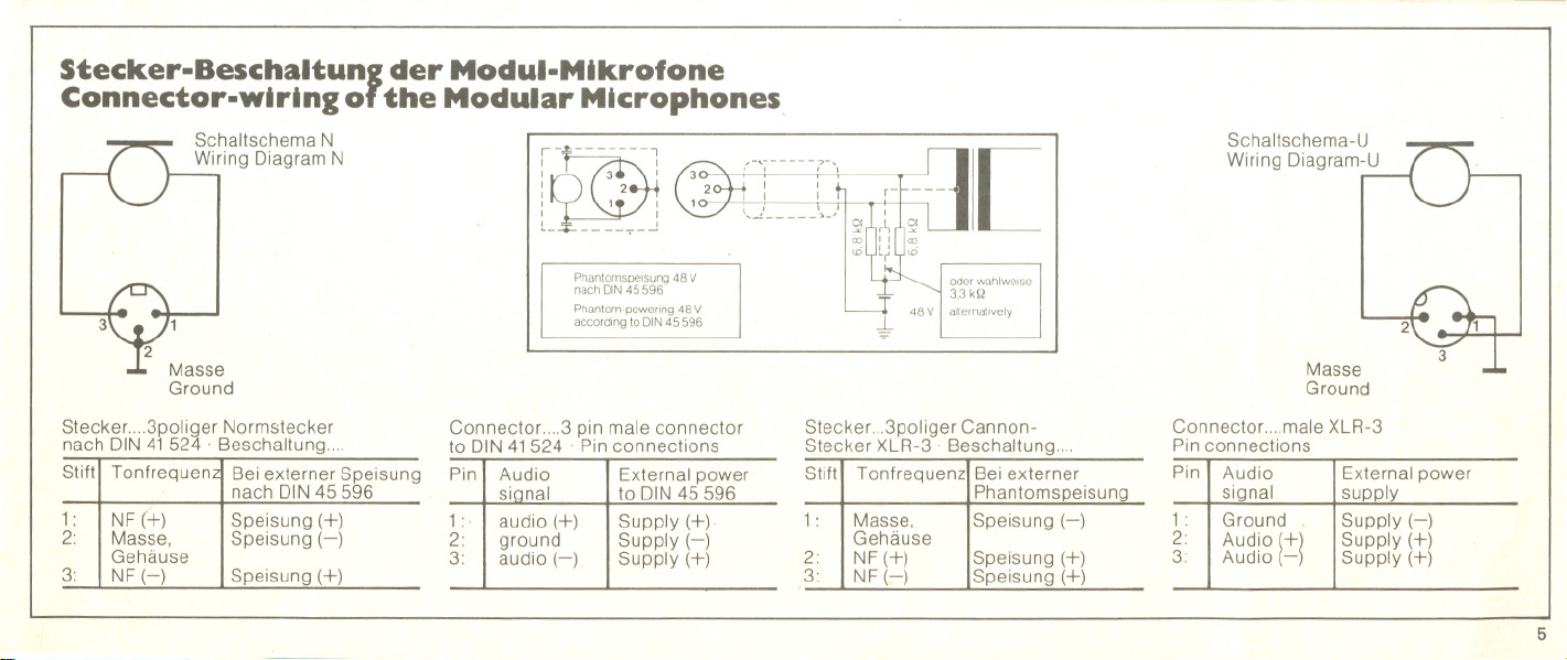
Bedienungshinweise:
Operations:
Batteriespa nnu ngskontrolle
Der Ein/A us-Schalter ist so ausgelegt,
daß beim Einschalten (rotes Feld sichtbar)
und Ausschalten des Mikrofons die zur
Batteriespannungskontrolle eingebaute
Diode kurzzeitig hell aufleuchtet, solange
die Betriebsspannung für das Mikrofon
ausreichend ist.
Wenn die Helligkeit erkennbar nachläßt, eingesetzt:
soll die Batterie gewechselt werden. Es Kontaktgabe und Funktion können durch
ist jedoch noch eine Reserve von etwa ein kurzzeitiges Ein- und Ausschalten
20 Stunden vorhanden, Zeit genug, um überprüft werden. Wenn die Leuchtdiode
eine Ersatzbatterie zu besorgen. Die während des Schaltvorgangs kurz auf-
normale Lebensdauer derBatterie be- leuchtet, ist die Batterie richtig einge-
trägt etwa 600 Stunden, Ersatzbatterien setzt worden. Anschließend wird der
sind in Fotofachgeschäften erhältlich. Mikrofonkopf wieder mit dem Batterie-
Ist das Mikrofon nicht in Gebrauch, so teil verbunden.
Ein'---Mus
On Off
soll es ausgeschaltet werden, um un-
nötiges Entladen der Batterie zu ver-
meiden.
Einsetzen der Batterie
Zum Batteriewechsel wird der Mikrofon-
kopf abgeschraubt, das Batteriefach ist
dann frei zugänglich.
Die Batterie, Typ Mallory PX 23, wird wie
auf dem Batteriefach-Aufkleber gezeigt,
-~
--~IiIl-
-~~-,
Leuchtdiode/Light emitting diode
Battery Voltage Check
The condition of the battery is checked
every time the microphone is switched on
(red mark visible) or off. When switching
the light emitting diode blinks indicating
sufficient supply voltage.
The microphone can be operated with one Proper connection and function are
battery for more than 600 hours. If the checked by switching the microphone on
signal of the diode becomes dim, the and off. When the light emitting diode
battery is coming to the end of its usable blinks the battery has been inserted right.
life. But there is still areserve of twenty The microphone head and the battery
hours left providing enough time to obtain part are now reassembled.
a new battery. New batteries are available
at shops for photo equipment. When the
microphone is not in use it should be
switched off to prevent unnecessary
discharging of the battery.
.. --_oe' ,
~
;:WI~! ...,...,.'. 11 ~:o .. .. I' .." j
.
...~ . - - -.- -................
f _Z ~~ ,
~
Inserting the Battery
To change the battery the microphone
head must be screwed off. The battery
compartment is then accessible.
The battery, type Mallory PX 23, should
be inserted as shown on the label in the
compartment.
15
Page 15

Aufstellung der
Mikrofone
Mountlng the
Mlcrophones
16
Die Mikrofone können mittels der mitge-
lieferten Stativ-Klemme MZG 104-1 auf
Bodenstative mit 3/8" Gewinde aufge-
schraubt werden. Für die Aufstellung auf
dem Tisch eignen sich der als Zubehör
lieferbare leichte. zusammenklappbare
Plastik- Tischfuß MZT 104 und der Studio-
Tischfuß MZT 105-1.
The microphones are supplied with a
quick release clamp MZG 104-1.This
clamp provides mounting of the micro-
phone on standard 3/8" tripod threads.
Two table stands are available as
optional accessories to which the clamp
may be alternatively mounted. The
MZT 104 is a light collapsable plastlc desk
stand and the MZT 105-1 is asolid metal
studio-type desk stand.
Page 16

Zubehör
Optlonal Accessorles
Tischfu8 MZT104 (Art.-Nr.0521)
Ein leichter, zusammenklappbarer Plastik-
tischfuß. Das abschraubbare Oberteil
paßt auf alle Mikrofonstative mit 3/8"-Ge-
winde.
Desk Stand MZT 104 (Art.-Nr. 0521)
A lightweight plastic stand. The swivel
clip may be detached and mounted on all
floor stands having a 3/8" thread.
Tischfu8 MZT105-1 (Art.-Nr. 0524)
Stabiler und feststehender Tischfuß für
den Studiobetrieb.
Desk Stand MZT105-1 (Art.-Nr.0524)
A stable and unobtrusive stand for studio
use.
17
Page 17

 Loading...