

Sennheiser HME 46-3PTT-LA, HME 46-3PTT-6, HME 46-ATC, HME 46-3PTT-M, HME 46-31 Service Manual
...
Service manual
Product variants
500857 HME 46-3
500467 HME 46-3-6
500874 HME 46-3PTT-M
500468 HME 46-3PTT-6
500469 HME 46-3PTT-L
502172 HME 46-3PTT-LA
500851 HME 46-ATC
502484 HME 46-31
500849 HMD 46-3
500466 HMD 46-3-6
500873 HMD 46-3PTT-M
502483 HMD 46-31
502594 HMD 46-3(5)
Cable variants
500836 -6
502360 -7
502365 -L
500844 -PTT-6
502418 -PTT-6-1
500845 -PTT-L
502187 -PTT-LA
500930 -D-3PTT-M
500931 -E-3PTT-M
Revision
02/2008
Air Traffic Control
HME 46-3
HMD 46-3
SA 070401
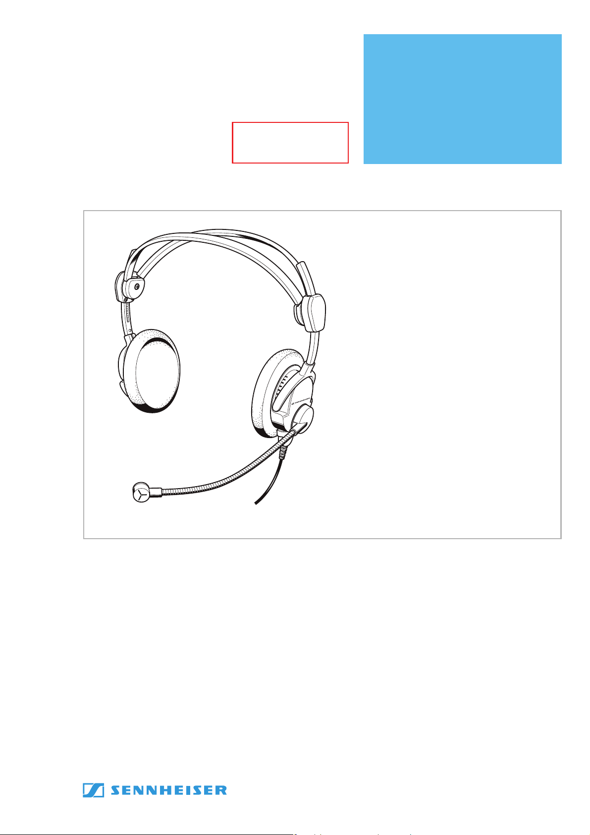
Short description
This headset features dynamic, open headphones. The noise-compensating
microphone ensures excellent speech transmission even in noisy
environments. Designed for air traffic control, intercom systems and other
communication purposes.
Features
• ActiveGard™ (not HME 46-31 and HMD 46-31)
• “Flip-away“ earcup
• Automatic two-piece headband
• Flexible microphone boom can be worn on either left or right-hand side
• Single-sided cable
• Comfortable wearing earpads
• PTT button integrated in the cable (HME/HMD 46-3PTT-x only)
Subject to alterations
Sennheiser electronic GmbH & Co. KG • 30900 Wedemark, Germany
Phone: +49 (5130) 600 0 • Fax: +49 (5130) 600 300 1/25

Safety requirements
Observe safety regulations.
Observe ESD instructions while handling electrostatically endangered components.
Only skilled perso
approved components according to the current spare parts list are allowed.
For safety and certification reasons it is forbidden to alt
authorization. Otherwise, the person who has
consequential damage.
repairs/exchanges The following instructions for overhaul and testing must
In case of unusual problems please contact yo
ns are allowed to alter and repa
ir. For repairs and exchanges only
altered the product is liable for any
ur Sennheiser distributor.
er the product without
be followed.
HME 46-3, HMD 46-3
2/25 02/2008

Contents
1 Outline dimension ..........................................................................................5
2 Technical Data.................................................................................................6
2.1 Headphones........................................................................................................... 6
2.2 Microphone of HMD 46-3.................................................................................... 6
2.3 Microphone of HMD 46-3(5) .............................................................................. 6
2.4 Microphone of HME 46-3 (with preamplifier) ................................................ 6
2.5 General data .......................................................................................................... 6
3 Disassembly ....................................................................................................7
3.1 Removal of the cable ........................................................................................... 7
3.2 Disassembly of the cap........................................................................................ 7
3.3 Disassembly of the cable .................................................................................... 7
3.4 Disassembly of the microphone arm ................................................................ 8
4 Assembly .........................................................................................................9
4.1 Assembly of the cap............................................................................................. 9
4.2 Assembly of the -PTT-x cable............................................................................. 9
4.3 Assembly of the cable to the headset............................................................10
4.4 Assembly of the microphone arm ...................................................................10
5 Testing and fault isolation......................................................................... 11
5.1 Tools and test equipment .................................................................................11
5.2 Operational test of the audio system............................................................. 11
5.2.1 Audio testing the headset with cable ............................................................11
5.2.2 Operational testing of the pre-polarized m
at the headset with cable (HME 46-3-x only) .............................................. 11
5.2.3 Testing of the dynamic microphone
a
t the headset with cable (HMD 46-3-x only)..............................................12
5.2.4 Operational testing of the headset cables .................................................... 12
Audio testing of the headset without cable .................................................12
5.2.5
5.2.6 Testing of the ActiveGard™ of the PCB (not HMD/E 46-31)...................... 13
icrophone
6 Wiring diagrams .......................................................................................... 15
6.1 Wiring diagram for cable -E-3PTT-M, -D-3PTT-M.........................................15
6.2 Wiring diagram for cable -PTT-L...................................................................... 16
6.3 Wiring diagram for cable -PTT-6..................................................................... 17
6.4 Wiring diagram for cable -PTT-LA................................................................... 18
6.5 Printed circuit boards ........................................................................................ 19
6.6 Block diagram......................................................................................................20
7 Exploded views with spare part lists........................................................ 21
7.1 Exploded view HME 46-3 / HMD 46-3 ............................................................ 21
7.2 Spare part list for HME 46................................................................................. 22
7.3 Spare part list for HMD 46 ................................................................................ 22
7.4 Exploded view of the system module ............................................................ 23
7.5 Spare part list of the system module
not microphone side (525764) .......................................................................23
7.6 S
7.7 E
7.8 Spare part list of the cap, microphone side...................................................24
7.9 Exploded view cable -PTT-x .............................................................................. 25
7.10 Spare part list for cable -PTT-x ........................................................................ 25
pare part list of the system module
microphone side (525763)............................................................................... 23
xploded view of the cap, microphone side ..................................................24
HME 46-3, HMD 46-3
02/2008 3/25
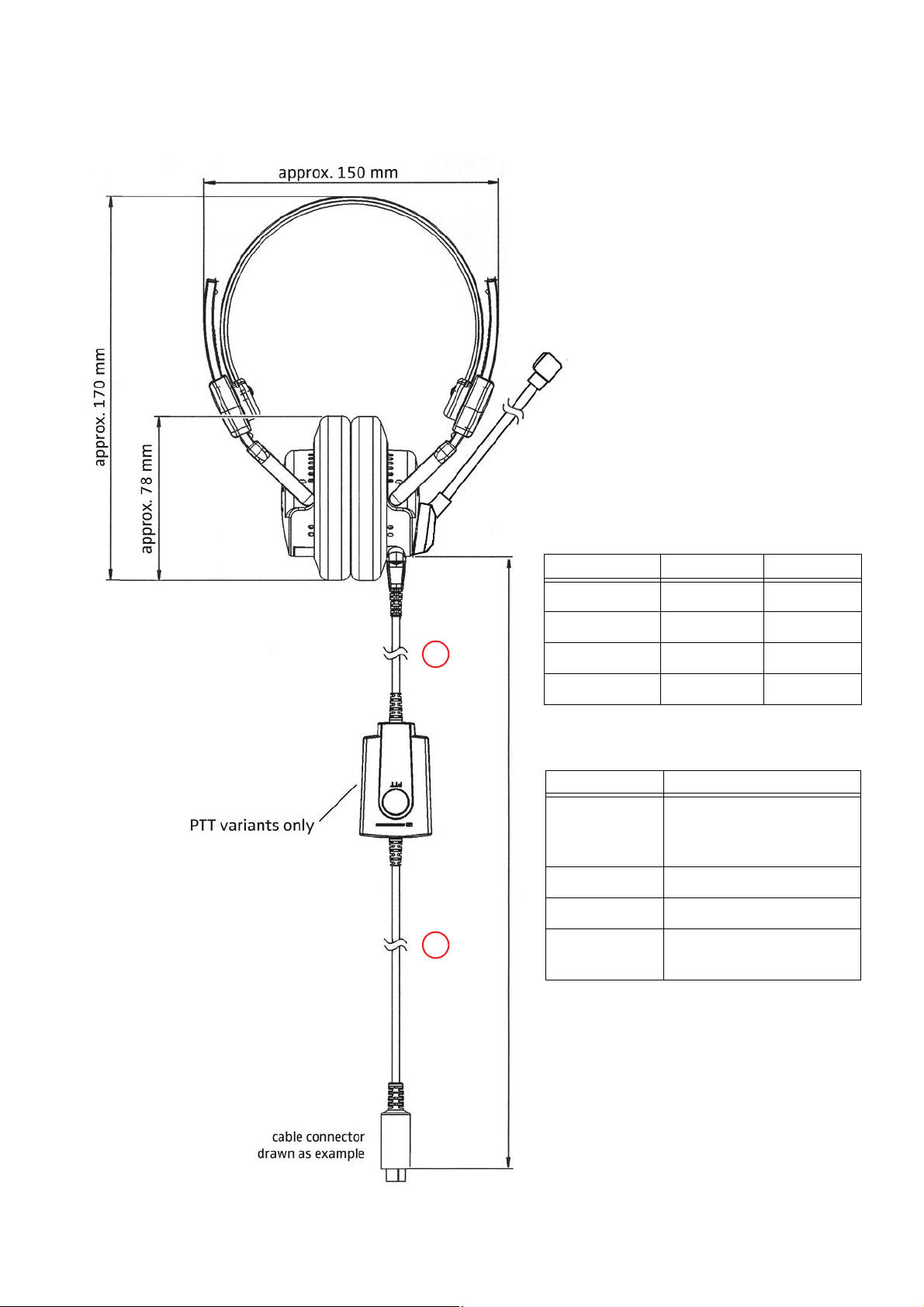
1 Outline dimension
1
2
Cable type Complete cable length
-PTT-6,
-PTT-6-1,
-PTT-L
1.85 m
-PTT-LA
2.30 m
-E/D-3PTT-M
2.45 m
-7,
-ATC / -L
2.00 m
Cable type
Length of
Length of
-E/D-3PTT-M 0.80 m
1.60 m
-PTT-LA 0.50 m
1.75 m
-PTT-L, -PTT-6 1.50 m
0.30 m
-PTT-6-1 0.80 m
1.00 m
HME 46-3, HMD 46-3
02/2008 5/25

2 Technical Data
2.1 Headphones
Transducer principle_______________________ dynamic, open
Ear coupling_____________________________ supra-aural
Frequency response _______________________ 20 to 14.000 Hz
Impedance _____________________________300 ohms per system
Sensitivity
HMD/E 46-3 _______________________ 95 dB/SPL at 1 kHz, 1 mW mono
83 dB/SPL at 1 kHz, 1 V
HMD/E 46-31 ______________________ 95 dB/SPL at 1 kHz, 1 mW mono
103 dB/SPL at 1 kHz, 1 V
THD
HMD/E 46-3 _______________________ < 1 % at 95 dB SPL (350 to 3.000 Hz)
HMD/E 46-31
Contact pressure _________________________aprx. 3.0 N
2.2 Microphone of HMD 46-3
Type _______________________________ MD 46-413
Transducer principle
Frequency response
Output voltage
Impedance
____________________________ 200 ohms
______________________< 1 % at 110 dB SPL (350 to 3.000 Hz)
_____________________ dynamic, noise compensating
______________________ 100 to 12.000 Hz
_________________________ 0.5 mV/Pa
2.3 Microphone of HMD 46-3(5)
Type _______________________________ MD 46-413_5 ohms
Transducer principle
Frequency response
Output voltage
Impedance
____________________________ 5 ohms
_____________________ dynamic, noise compensating
______________________ 100 to 12.000 Hz
_________________________ 0.125 mV/Pa
2.4 Microphone of HME 46-3 (with preamplifier)
Type _______________________________ MKE 46
Transducer principle
Frequency response
Output voltage
HME 46-3, -3-6, -3PTT-M,
-3PTT-6, -3PTT-L, HME 46-31
HME 46-3PTT-LA, -ATC adjustable from 17 to 215 mV/Pa,
Terminating impedance
Supply voltage
_____________________ pre-polarized condenser microphone, noise compensating
______________________ 350 to 6.000 Hz
__________ adjustable from 17 to 100 mV/Pa,
80 mV/Pa (factory pre-set) ≅ 800 mV at
152 mV/Pa (factory pre-set) ≅ 1520
___________________ 150 to 2.200 ohms
_________________________ 8 to 16 V DC
114 dB SPL
mV at
114 dB SPL
2.5 General data
Ambient temperature
operating mode ___________________ -15°C to 55°C
stocking
Weight, without cable
6/25 02/2008
_________________________ -55°C to 70°C
____________________ aprx. 150 g
HME 46-3, HMD 46-3

3 Disassembly
3.1 Removal of the cable
Reference:
• see “Exploded view HME 46-3 / HMD 46-3”, page 21.
1. Loosen the screws of the cable.
2. Remove the cable from the cable holder (110).
3.2 Disassembly of the cap
Reference: see “Exploded view HME 46-3 / HMD 46-3”, page 21.
1. Remove the earpad (90) from the relevant cap (20 or -25).
2. Lift the sides of the discs (80), now the screws (70) are visible
caps (20 or -25) completely if necessary.
3. Remove the screws (70).
4. Pull out the the resonator (60) with capsule.
5. Remove the center (50).
6. Remove the felt plate (40).
7. Unsolder the leads of the cable (TP1 to TP4) of t
see “Printed circuit boards”, page 19.
8. Unsolder the leads from the capsules (TP8, TP9), see “Printed circuit boards”, page 19 or see “Exploded view of the system module”, page 23.
9. Unsolder the cable from the microphone arm (100 or -105) (TP5 to TP7)*.
10.
Remove the cable holder (110) from the cap (20)*.
11. Remove the cap (20 or -25) from the split headband (10).
he split headband (10) from the PCB,
or remove the discs (80) from the
3.3 Disassembly of the cable
Reference: see “Exploded view cable -PTT-x”, page 25.
1. Remove the four screws (40) of the housing (10).
2. Open the housing (10, 30).
3. Remove the inserts (50).
4. Take out the PCB (60) and the cables (90, 100) of the
5. Desolder the cables (90, 100) from the PCB (60).
housing (10).
* Only microphone side.
HME 46-3, HMD 46-3
02/2008 7/25
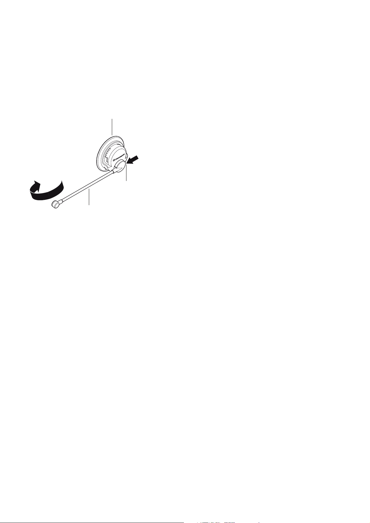
3.4 Disassembly of the microphone arm
100
20
10 (of the cap module)
Reference: see “Exploded view HME 46-3 / HMD 46-3”, page 21 or see “Exploded view of the cap, microphone
side”, page 24.
1. Rotate the microphone arm (100 or
-105) to the side position if necessary
(see figure below).
2. Screw the threaded pin (10 of the cap module) completely into the microphone arm fixing
3. Disassemble the microphone arm (100 or -105) from the cap (20) by
moving the microphone down
towards to the other cap (-25) of the headset .
.
HME 46-3, HMD 46-3
8/25 02/2008

4 Assembly
4.1 Assembly of the cap
Reference:
• see “Exploded view HME 46-3 / HMD 46-3”, page 21.
1. Attach the relevant cap (20 or -25) to the headband (10).
2. Solder the relevant leads of the split headband cable to the PCBs (TP1 to TP4), see “Printed circuit boards”, page 19 and see “Block diagram”, page 20.
3. Solder the microphone cable (TP5 to TP7) at the microp
and see “Block diagram”, page 20.
4. Put the center (50) over the resonator (60) and solder
(TP8 and TP9) to the PCB , see “Printed circuit boards”, page 19 and see “Block diagram”, page 20.
5. Install the felt plate (40) on the PCBs
6. Turn the center (50) into the cap (20 or -25).
7. Set the capsule with resonator (60)
8. Install the screws (70) with a torque of 25 Ncm
9. Install the label (120) on the cap (-25), if applicable.
10. Install the disc (80) on the resonator (60) if necessary.
11. Install the earpad (90) over the disc (80) on the cap (20 or -25).
(20 of the system module).
into the cap (20 or -25).
±3 Ncm.
4.2 Assembly of the -PTT-x cable
hone arm PCB, see “Printed circuit boards”, page 19
the orange and brown leads at the relevant pins
Reference: see “Exploded view cable -PTT-x”, page 25
1. Solder the cables (90, 100) at the PCB (60), see “Wiring diagrams”, page 15 et sqq.
2. Install the PCB (60) with the cables (90, 100) into the housing (10).
3. Close the housing (10) with the cover (30).
4. Install the inserts (50) at the top of the housing (10).
5. Fasten the screws (40) of the housing (10) with a torque of 25
Ncm ±3 Ncm.
* Only for microphone side.
HME 46-3, HMD 46-3
02/2008 9/25
 Loading...