

Sennheiser GuidePort, GuidePort SR 3000-2, GuidePort AM 3000, GuidePort Receiver, Identifier Transmitter System Manual
Page 1

GuidePort – EMP
System Manual
Version 1.0 of 27 July 2000
Sennheiser electronic GmbH & Co. KG
Am Labor 1
30900 Wedemark
Germany
Page 2

GuidePort: System Manual 27. November 2000 Seite 2
1 GuidePort Wireless Audio Transmission
GuidePort is a local area broadcast system for use in museums, visitor centers and at
exhibitions. GuidePort features a characteristic cell structure, the so-called cells being
defined areas of information and entertainment. These areas are supplied by Cell
Transmitters which send digitally coded information via an Active Antenna Unit to
portable Receivers. The transmitted data can be any audio information, for example
comments or music. The audio signals are picked up by bodypack receivers which play
the audio program directly via headphones. The various audio programs (events) can
be triggered automatically by magnetic field identifiers.
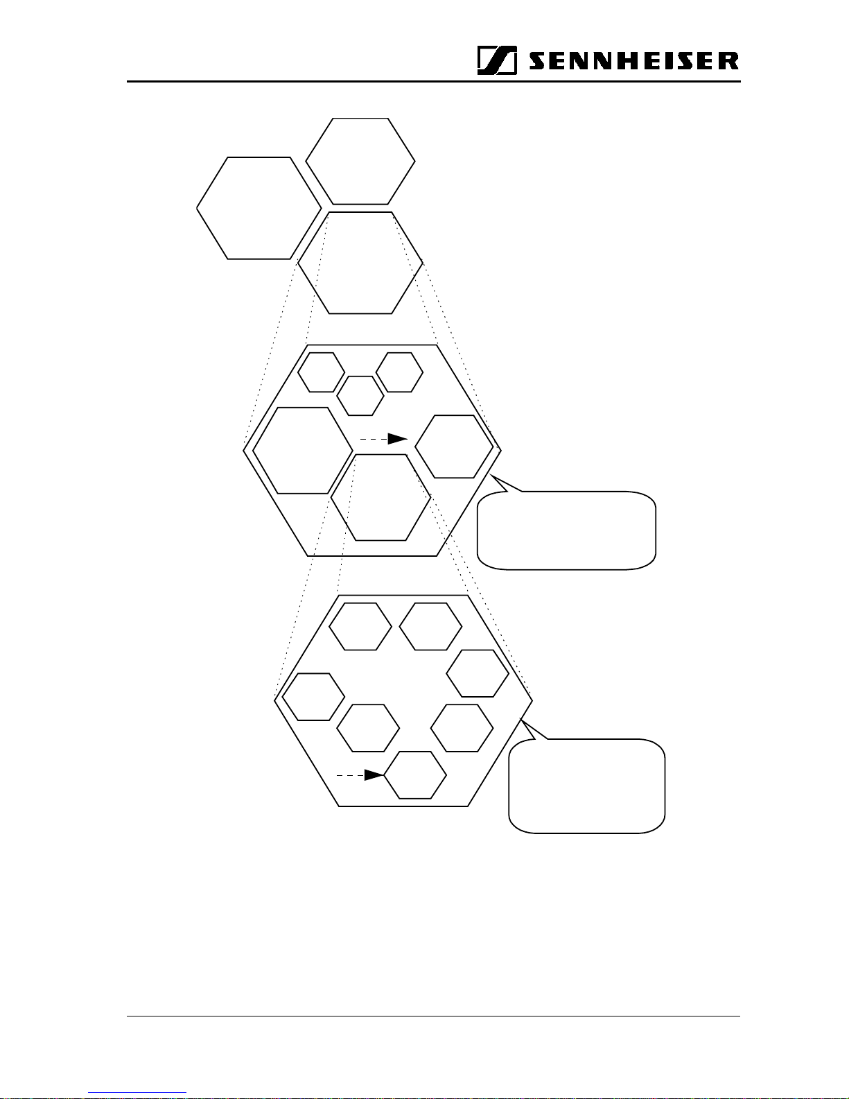
The diagram on the next page shows GuidePort’s system hierarchy. At the top level are
the GuidePort installations. Each installation carries a specific code transmitted via RF.
Whenever a GuidePort receiver recognizes a new installation code, it will automatically
collect the installation-specific control data. This data is mainly the so-called Event
Assign Table which defines the receiver’s “reactions” to the 255 possible event
numbers available in each installation, making the receiver compatible with other
separate, independent GuidePort installations.
An installation can be seen as a macro cell. Each installation can be organized in up to
255 cells and contains up to 255 real-time audio events.
Page 3
GuidePort: System Manual 27. November 2000 Seite 3
GuidePor
t
Installation
INST. No. 1
GuidePor
t
Installation
INST. No. 3
GuidePor
t
Installation
INST. No. 2
cell 1
cell 2
cell 3
cell 4
…
cell 255
cell 5
GuidePort Cell
with one or more
Cell Transmitters
Event 1 Event 2
Event 3
Event 5
Event 4
Event 6
Event
One installation
can handle up to 255 events
which may be organized in
up to 255 cells
GuidePort System Hierarch
y
One
cell transmitter
can handle up to 4
mono audio channels
and transmit them on
one RF channel
Page 4
GuidePort: System Manual 27. November 2000 Seite 4
Cell Transmitte
r
Central Unit PC with
• GP Central Unit
Software
• Sound card with a
samplingrateof
32 kHz
• G7++ converter and
announcement
software
Base Station PC
with
Cell Transmitter
Loader Software
Base Station PC
with
Cell Transmitter
Loader Software
Audio Source 1 -4
PC Network
Base Station PC
with
Cell Transmitter
Loader Software
USB Hub
USB
USB Hub
Audio Source 1 -4
Active
Antenna Unit
RF CH 1
Cell Transmitte
r
Active
Antenna Unit
RF CH 4
Cell Transmitte
r
Event
#3
Event
#4
Event
#5
Event
#6
GP
Receiver
Ext.
Antenna
(
opt.
)
Event
#2
Event
#1
Exhibition
room 1
Exhibition
room 2
Exhibition
room 3
Exhibition
room 7
Technical
room 1
LVDS
LVDS
USB
Exhibition
room 5
Exhibition
room 6
Exhibition
room 4
Technical equipment required for an exhibition with GuidePort
Supervisor
Page 5
GuidePort: System Manual 27. November 2000 Seite 5
2 Hardware Components of the System
2.1 Central Unit PC
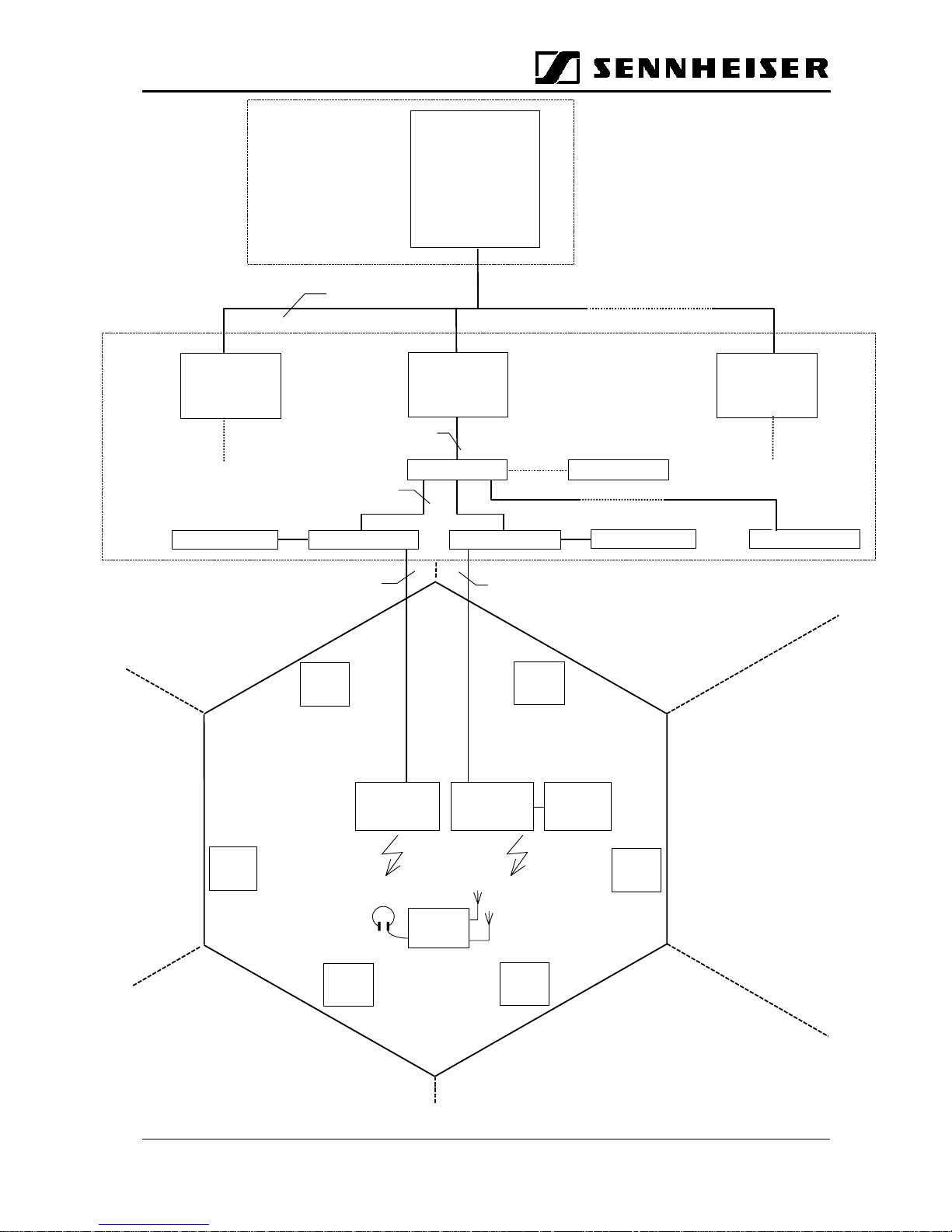
The Central Unit PC with its Central Unit Software is at the heart of the GuidePort
system. It serves to configure the entire GuidePort installation with its cells,
transmitters, events and identifiers. Via a network, the Central Unit PC is connected
with all Base Station PCs of the GuidePort installation.
2.2 Base Station PC
The Base Station PC with its Cell Transmitter Loader Software detects the IDs of all
Cell Transmitters connected to it via a USB. The Base Station PC will transmit the
configuration files created by the Central Unit Software to the Cell Transmitters.
2.3 Cell Transmitter
2.3.1 Description
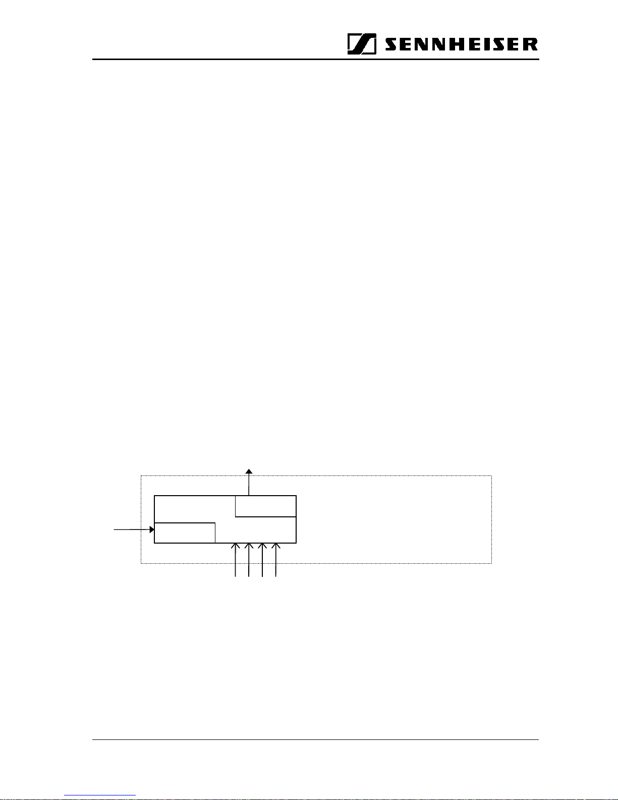
A Cell Transmitter is a digital unit which picks up prepared MTS data and combines
them with installation-specific control tables and the real-time audio information from its
four analog audio inputs. Via an LVDS interface, the entire data stream is sent to an
Active Antenna Unit where FSK modulation and RF conversion take place. The
transmission of the MTS data is done in a cyclic manner. The cable length between the
Cell Transmitter and the Active Antenna Unit may amount to up to 150 m, which
ensures a convenient installation of the local antennas.
1234
Analog RTA Inputs
Cell Controller
Unit
USB
Interface
LVDS
Interface
Data
Download
To Active Antenna Unit
Base Station
Page 6
GuidePort: System Manual 27. November 2000 Seite 6
2.3.2 Hardware Interfaces
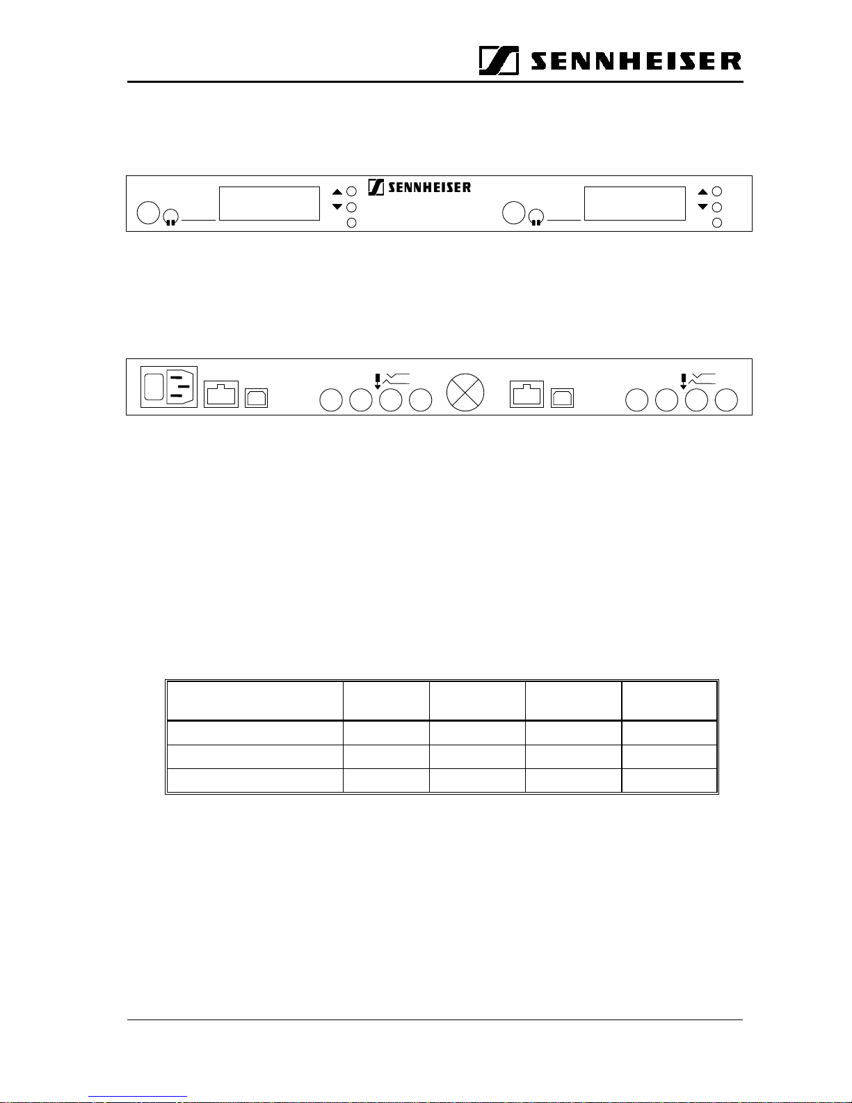
a) Front panel
Headphone Outputs
Allow you to monitor the audio signals transmitted to the receivers.
b) Rear panel
USB IN:
Input socket for the USB cable from the Base Station PC.
ANALOG IN SYM.:
Inputs for connecting your audio sources to the transmitter. There are four balanced
inputs, you can either connect 4 mono sources, 2 mono sources and 1 stereo source or
2 stereo sources. For a stereo audio source, you will need two sockets (left and right
channel), please use inputs 1 & 2 and/or 3 & 4. Connect the left audio channel to
socket No. 1 or 3, the right audio channel to No. 2 or 4, respectively.
The following table shows how to connect your audio sources to the GuidePort Cell
Transmitter:
Number and kind of audio
sources
Input No. 1 Input No. 2 Input No. 3 Input No. 4
4 mono (m) m m m m
2mono(m),1stereo(s) m m s,left s,right
2 stereo (s) s, left s, right s, left s, right
AAU OUT
Output for connection of an Active Antenna Unit. Use a shielded, 8-wire twisted pair
cable (4 individually twisted pairs) for connection. This cable supplies the Active
Antenna Unit with DC and the digital data stream to be transmitted.
SET SET
GuidePortSR3000
-2
TX I TX II
TX II
AAU OUT
0
I
USB IN
ANALOG IN SYM.
TIP: +
-
1
234
TX I
AAU OUT
USB IN
ANALOG IN SYM.
TIP: +
-
1
234
Page 7
GuidePort: System Manual 27. November 2000 Seite 7
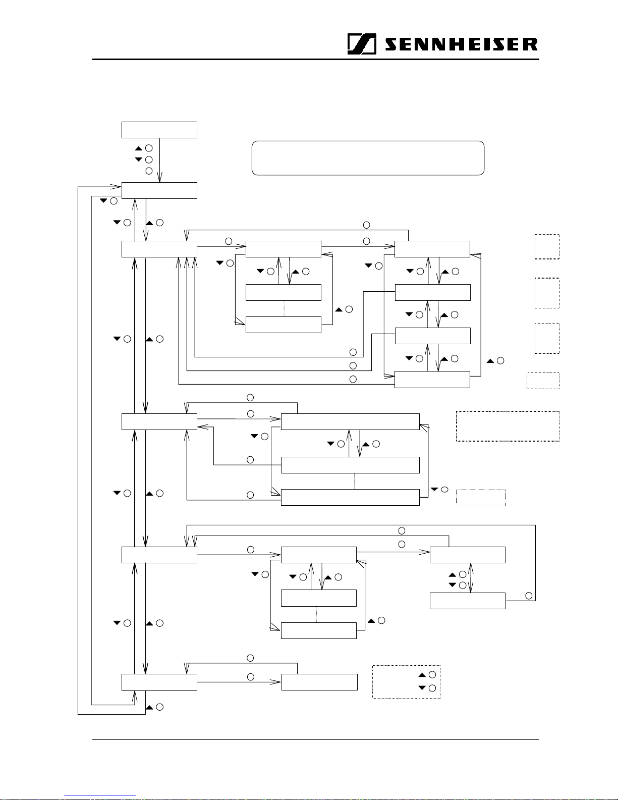
2.3.3 User Interface (Display and Controls)
Menu layout of the GuidePort Cell Transmitter:
AAU SETTINGS
SET SET
AAU 01
AAU 02
AAU 08
RF CHxx
EXT ANT xx
MTS xx
RF ATTEN xx
SET
SET
SET
1...95
NC
ON
OFF
NC
01
02
OFF
00...06
TX OK
CCU ID xxx
SET
SET
RTA VOL VOL xx
SET
Max. 32
Default 16
Min. 1
SET
RTA CH ON
OFF
SET
SET
SET
CH 01 xx
CH 02 xx
CH 04 xx
SET
N.B.: If there is no input for about 90 secs
the display will show “TX OK”
SET
SET
RTA ID
SET
CH 01 {event name} { event ID}
CH 02 {event name} { event ID}
CH 12 {event name} { event ID}
SET
e.g.
CH 01 Jimi Hendrix 005
N.B.: Text will be scrolled.
CH 12 NC
Page 8

GuidePort: System Manual 27. November 2000 Seite 8
2.3.4 Technical Data
AF IN
Frequency 40 - 14,000 Hz
Input level mV
rms
Impedance 660
Ω
balanced input
Audio sources 4 mono
2stereo
1 stereo, 2 mono
AF IN 1, 2, 3, 4
AFIN1&2(1=left,2=right)
3&4; (3 = left, 4 = right)
AF IN 1&2 or 3&4 (stereo);
remaining inputs for mono
sources
USB IN
AAU OUT
DC output +15 V
I
ma
x
200 mA
Data rate 1,024 Mbit/s
Output level 350 mV
pp
LVDS standard
Headphone Output
Output level mV
pp
AF input level 350mV
rms
Output impedance 32
Ω
Page 9
GuidePort: System Manual 27. November 2000 Seite 9
2.2 Active Antenna Unit
2.2.1 Description
The Active Antenna Unit receives the data stream from the Cell Transmitter via an
LVDS interface. The data stream is then FSK modulated onto an RF carrier in the 2.4
GHz ISM Band and transmitted to the GuidePort receivers. Settings for transmission
frequency, RF output power and the antenna to be used (internal or external antenna)
are controlled by the Cell Transmitter.
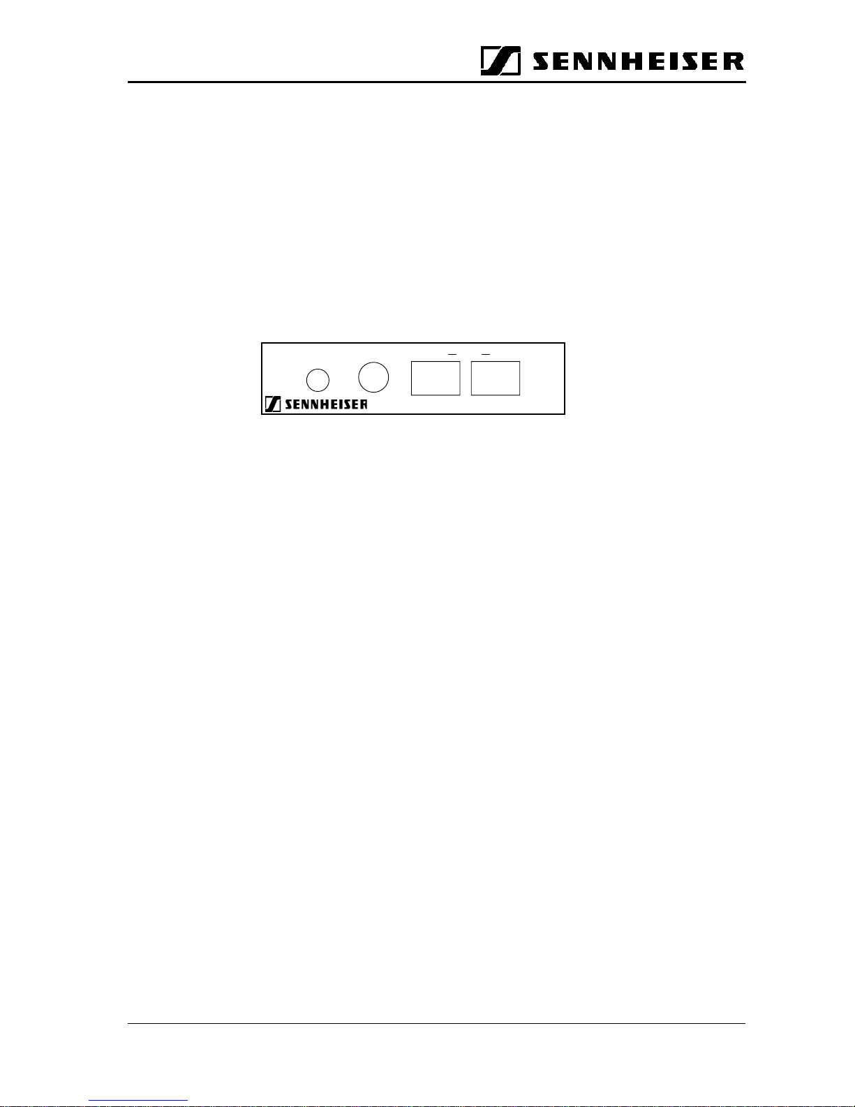
2.2.2 Hardware Interfaces
MTS IN
Connects the Active Antenna Unit to the GuidePort Cell Transmitter. The connection
cable supplies the Antenna Unit with both DC and the digital data stream to be
transmitted. When the associated Cell Transmitter is switched on, it will automatically
configure the Antenna Unit.
MTS OUT
For connecting (daisy-chaining) a second Active Antenna Unit. The second Antenna
Unit will transmit the same data stream, but on another RF carrier. This feature is not
available in this customized version, instead you can connect measuring equipment to
MTS OUT.
RF OUT
For connecting an optional, external directional antenna. If you want to use an external
antenna, you have to select the “External Antenna” option when configuring the Cell
Transmitter with the Central Unit software.
2.2.3 User Interface
ADDRESS
The Active Antenna Unit is automatically configured by the Cell Transmitter when the
transmitter is switched on. The default address is No. 1. Presently, other addresses are
not supported.
RF OUT ADDRESS OUT M TS IN
GuidePort AM 3000
Page 10
GuidePort: System Manual 27. November 2000 Seite 10
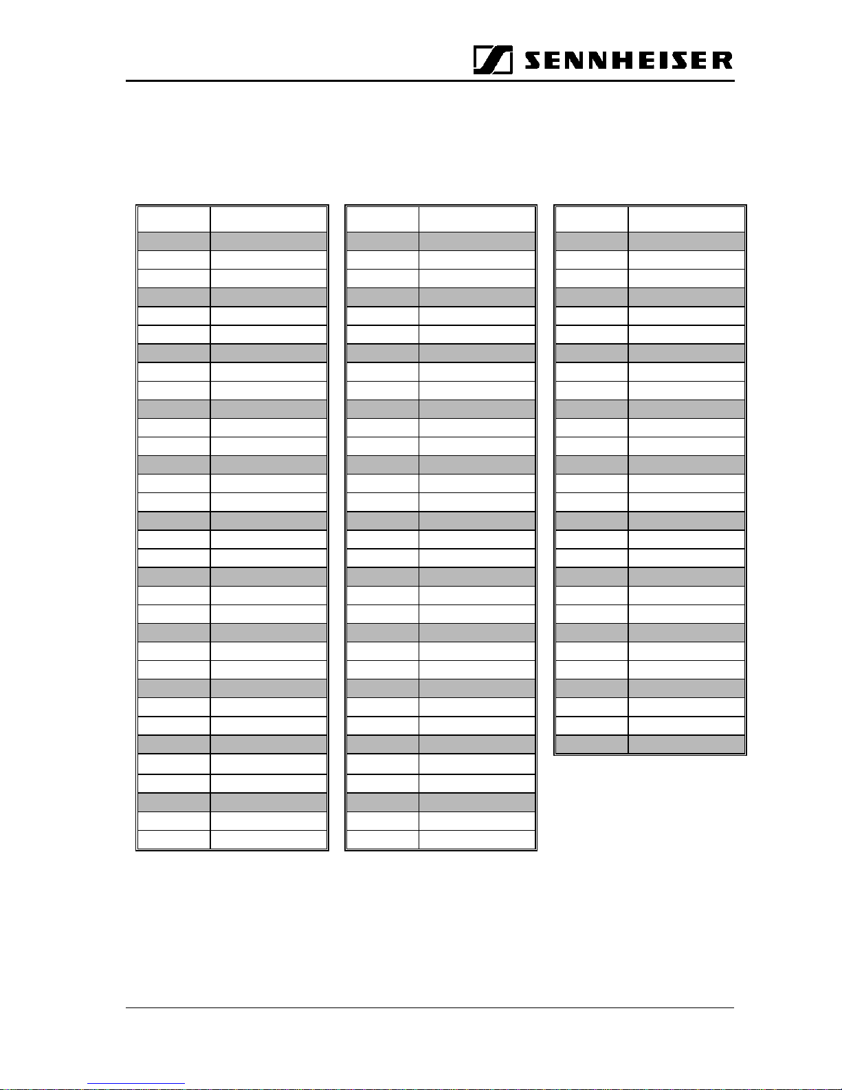
2.2.4 Available RF Channels
The following RF Channels can be chosen when configuring the Active Antenna Unit
via the Central Unit Software. The highlighted channels (grey) are preferred channels.
Please do not forget a minimum channel spacing of 3 channels within one cell.
RF Ch. Frequency [MHz] RF Ch. Frequency [MHz] RF Ch. Frequency [MHz]
1 2401.920 34 2430,432 67 2458.944
2 2402.784 35 2431,296 68 2459.808
3 2403.648 36 2432,160 69 2460.672
4 2404.512 37 2433,024 70 2461.536
5 2405.376 38 2433,888 71 2462.400
6 2406.240 39 2434,752 72 2463.264
7 2407.104 40 2435,616 73 2464.128
8 2407.968 41 2436,480 74 2464.992
9 2408.832 42 2437,344 75 2465.856
10 2409.696 43 2438,208 76 2466.720
11 2410.560 44 2439,072 77 2467.584
12 2411.424 45 2439,936 78 2468.448
13 2412.288 46 2440.800 79 2469.312
14 2413.152 47 2441.664 80 2470.176
15 2414.016 48 2442.528 81 2471.040
16 2414.880 49 2443.392 82 2471.904
17 2415.744 50 2444.256 83 2472.768
18 2416.608 51 2445.120 84 2473.632
19 2417.472 52 2445.984 85 2474.496
20 2418.336 53 2446.848 86 2475.360
21 2419.200 54 2447.712 87 2476.224
22 2420.064 55 2448.576 88 2477.088
23 2420.928 56 2449.440 89 2477.952
24 2421.792 57 2450.304 90 2478.816
25 2422.656 58 2451.168 91 2479.680
26 2423.520 59 2452.032 92 2480.544
27 2424.384 60 2452.896 93 2481.408
28 2425.248 61 2453.760 94 2482.272
29 2426.112 62 2454.624
30 2426.976 63 2455.488
31 2427.840 64 2456.352
32 2428.704 65 2457.216
33 2429.568 66 2458.080
Page 11
GuidePort: System Manual 27. November 2000 Seite 11
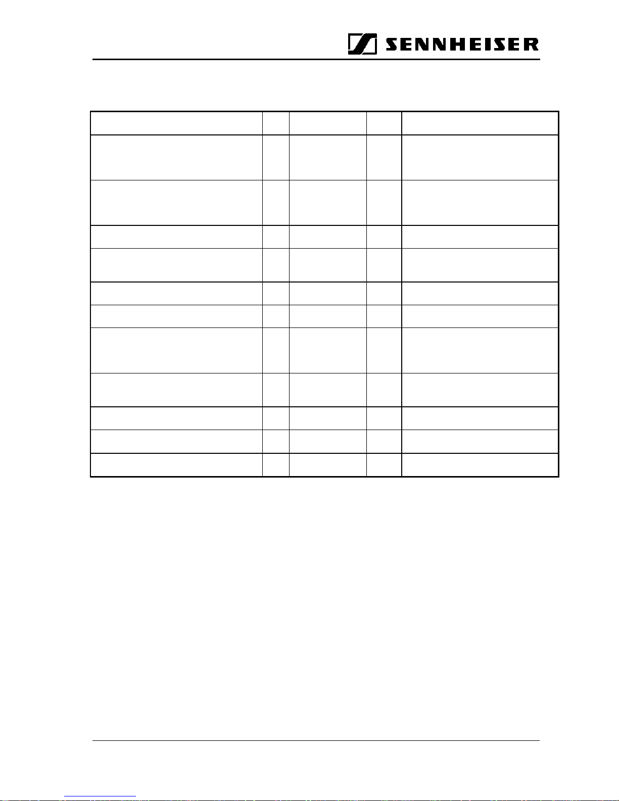
2.2.5 Technical Data
RF transmission frequency range f 2.4 - 2.4835 GHz
Max. radiated RF peak power P 1
0
mW
dBm
ERP for North America in
compliance with FCC
P1010mW
dBm
ERP for Europe in compliance with
ETS 300 440
RF antenna internal chip antenna, mounted on board
external directional, wall-mounted antenna
(opt.)
RF channel bandwidth f 2.6 MHz
Total number of RF channels 94
Transmission range of cell transmitter
for quasi error-free reception, no walls
s
s
>30
>50
mm1 mW RF peak power
10 mW RF peak power
Spurious frequencies outside the ISM
band
in compliance with ETS/FCC
Modulation type 2-FSK binary frequency shift keying
Modulation index µ 0.5 ... 0.7
µ =2*∆f/f
bit
Modulated data rate f
bit
/channel 1024 kbit/s
Page 12

GuidePort: System Manual 27. November 2000 Seite 12
2.3 Receiver
2.3.1 Description
The GuidePort Receiver automatically reacts to the magnetic fields created by
Identifier Transmitters (see 2.4). These Identifiers transmit a number which is related
to a certain audio event. When receiving this number, the receiver will transfer the
corresponding audio information to the Mollie System. Mollie then decides on the action
to be taken, for example to play the audio information. The GuidePort Receiver uses a
prestored assignment table for translating the numbers into the correct action.
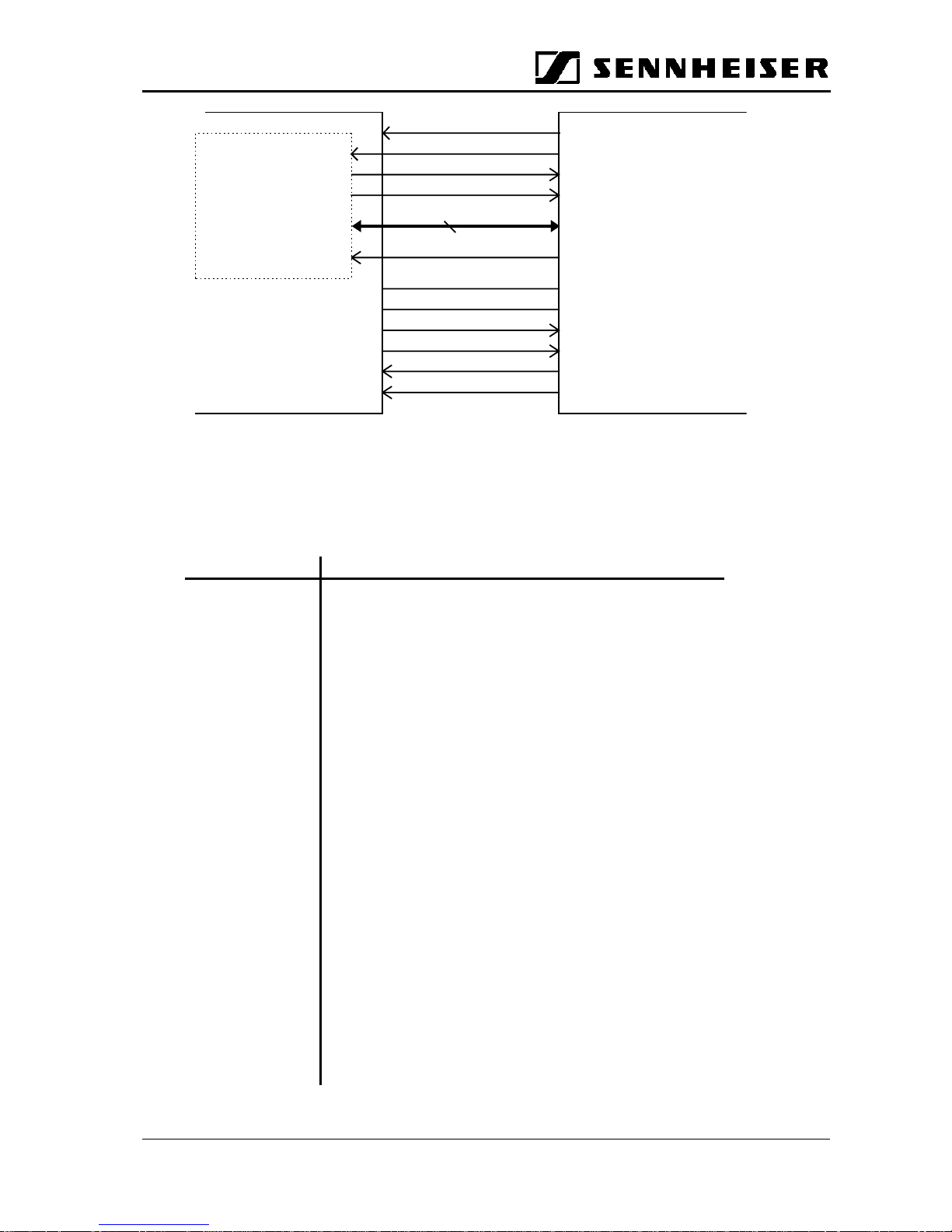
2.3.2 Mollie Interface
The physical interface consists of:
Function No. of lines Direction
Analog:
Analog audio signals (L, R) 2 from GP receiver to Mollie
3.3 V power line, digital 1 from Mollie to GP receiver
5 V power line, analog 1 from Mollie to GP receiver
Analog ground 1 or more
Digital:
Parallel data 8 bi-directional
'Interrupt_1' (Active Low) 1 from Mollie to GP receiver
'Read/Write' 1 from Mollie to GP receiver
'Reset' (Active Low) 1 from Mollie to GP receiver
'Frame Clock' 1 from GP receiver to Mollie
'Interrupt_2' 1 from GP receiver to Mollie
Digital ground 1 or more
Page 13
GuidePort: System Manual 27. November 2000 Seite 13
Logical level of all digital lines: according to LVTTL (3.3V)
Interface Connector GP receiver: JST flat multicore cable, type 24FLZ-SM1-TB
Pin Assignment of Interface Connector 24FLZ-SM1-TB:
Pin No. Function
1 analog ground for audio, from GP receiver
2 left audio channel, from GP receiver
3 analog ground for audio, from GP receiver
4 right audio channel, from GP receiver
5 analog ground for audio, from GP receiver
6 digital ground for digital interface
7 data bus, bit 0, LSB
8 data bus, bit 1
9 data bus, bit 2
10 data bus, bit 3
11 data bus, bit 4
12 data bus, bit 5
13 data bus, bit 6
14 data bus, bit 7, MSB
15 Read/Write
16 Frame Clock
17 Interrupt_2
18 Reset
19 Interrupt_1
20 digital ground for digital interface
21 3.3 volts digital power, from Mollie
22 digital ground from Mollie
23 analog ground from Mollie
24 5 volts analog power from Mollie
3.3 Volt, digital
analog audio R
analog audio L
AGND
DGND
Read/Write
8Data
Frame Clock
Reset
DSP
56 303
Mollie
GuidePort
Receiver PCB
PB0.....PB7
PB8
PB9
Interrupt_1
IRQA
SCLK
Interrupt_2
5 Volt, analog
Page 14
GuidePort: System Manual 27. November 2000 Seite 14
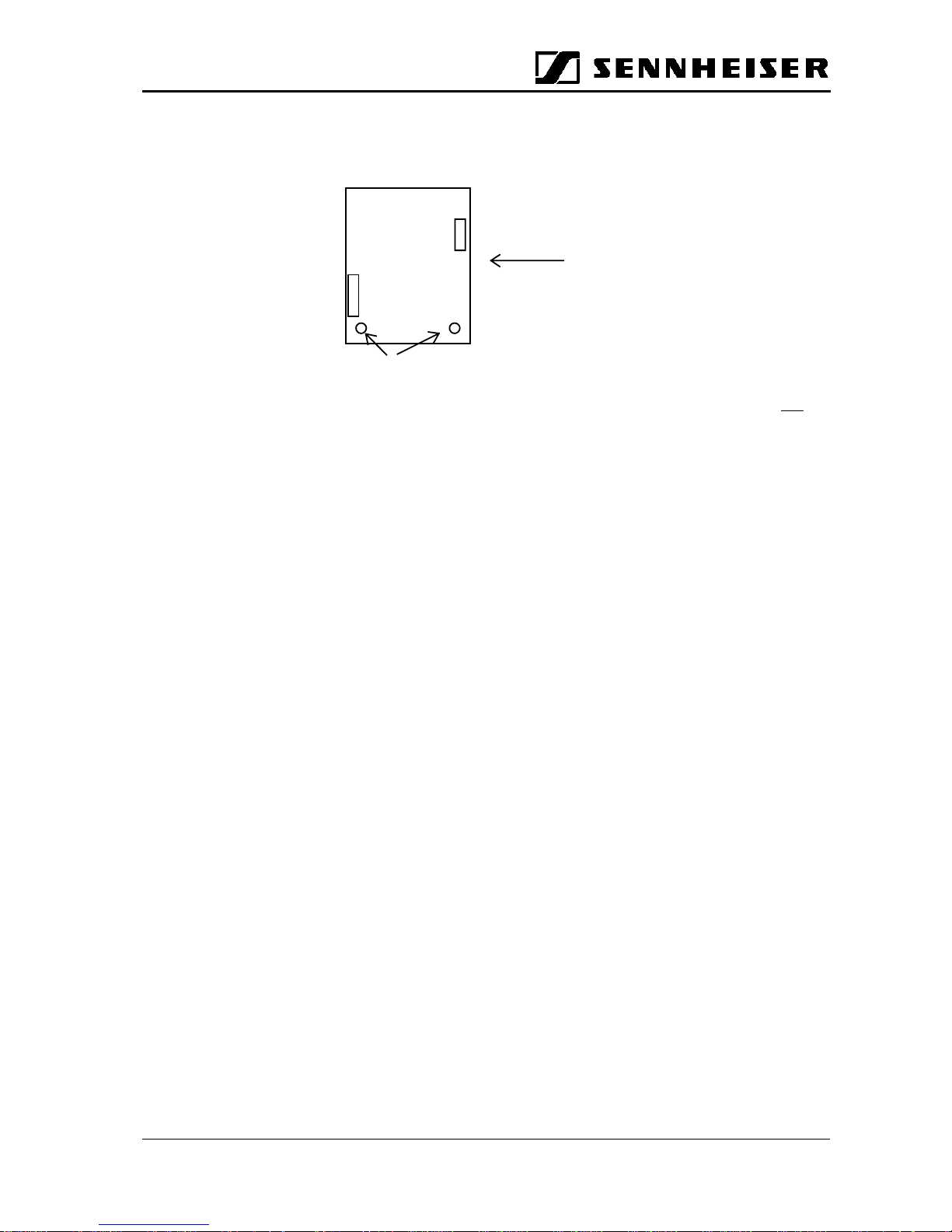
Mounting of PCB and Position of Connectors:
It is of the utmost importance to mount the GP receiver board in a vertical position:
'Reset': reset is active when 'low', internal connection on GuidePort receiver PCB: MR of
MAX811 (pin 3)
'Interrupt_1 ': Interrupt_1 is active when 'low'. Mollie’s read or write procedures always start
with the interrupt request. The first interrupt tells the GP receiver that Mollie has
put an address word on the bus. During the power on procedure or a Reset from
Mollie the line must be in the high ohmic state or 'High'. Interrupt_1 is not allowed
if Interrupt_2 is active (low).
Connection on GP receiver: IRQA of DSP56303.
'Read/Write': When Mollie has activated the interrupt and put an address word on the bus, the
Read/Write line determines whether Mollie wants to read from or write into the
related register. 'High' means 'read', 'Low' means 'write'. Connection on GP
receiver: PB 8 of DSP 56 303.
8-bit parallel data: bi-directional data bus
Connection on GP receiver: PB 0.........PB 7 of DSP56303
LSB = PB 0, MSB = PB 7
'Frame Clock': The Frame Clock coming from the GuidePort receiver indicates that the receiver
has synchronized with the received bit stream and that real-time audio is
available.
'Frame Clock' = low: no synchronization, no audio
'Frame Clock' = high: frame synchronization has taken place, audio is available
'Interrupt_2': This is an impulse from the GuidePort receiver indicating Mollie that certain
conditions have been fulfilled. These conditions are:
Either • there is a change in the identifier number register
and/or • the bit error statistic exceeds the limit defined in the Error Limit
register (Bit Error Statistic Register)
and/or • a new GP Message is available(GP Message Register)
During register updating, Interrupt_2 is 'low'. As the time required is very short
(≈100ns), the detection of the Interrupt_2 signal should be edge controlled using
the positive edge. All above mentioned registers are updated within one write
cycle, which means that more than one register may change its content. This
makes sense because if there is an old error message in the GP Message
Register from the last update, it is now deleted if it is invalid (see also appended
flow charts).
Interrupt_2 is not allowed during Mollie’s Read/Write routines.
Pin 1
Pin 24
24FLZ connector for
GP/Mollie interface
Cable direction
Identifier
coil
Connectors for RF antennas
Page 15
GuidePort: System Manual 27. November 2000 Seite 15
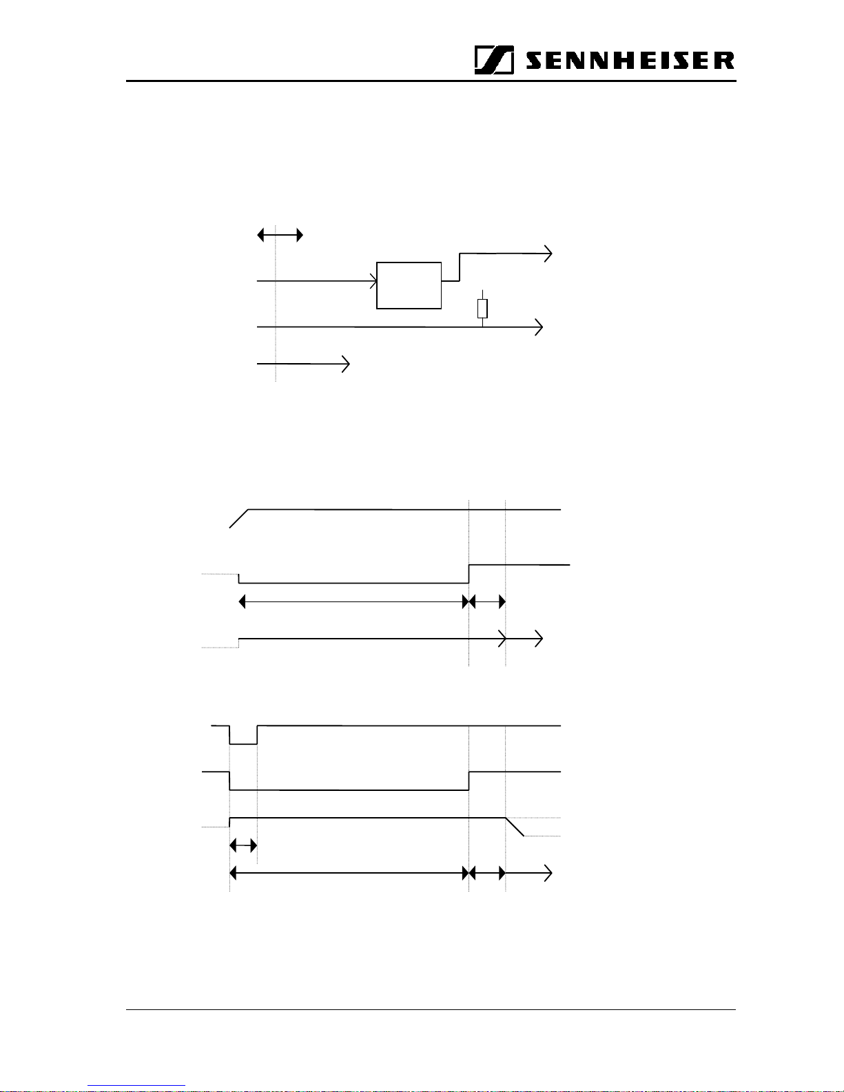
Specification for the Reset Procedure between GuidePort/EMP and Mollie
Simplified hardware diagram:
Remark: Other lines of the GP/Mollie interface are not of interest for this subject.
1. Case: Power is switched on
When the 3.3 V power line becomes high the IC Max811 generates a ≈ 280 ms reset
impulse.
2. Case: Reset from Mollie (during power on)
receiver ready
power
285ms 40ms
DSP
reset
IRQA
Reset IC
Max 811
Reset for
DSP56303
Master
Reset
GPMollie
Reset line
from Mollie
IRQA of DSPInterrupt_1
3.3 VDC for digital circuit
10k
Vcc
reset from
Mollie
IRQA
DSP
reset
Tmr = 5 to 10us
285 ms
40ms
receiver ready
Page 16

GuidePort: System Manual 27. November 2000 Seite 16
2.3.3 Technical Data
RF receiving frequency range f 2.4 - 2.4835 GHz
Input sensitivity at antenna input P -93 dBm BER 10
-3
RF antenna connector MMS female
Input impedance 50
Ω
Power supply
Analog Voltage U 5 V 10% tolerance
Max. current I 110 mA
Digital U 3.3 V 10% tolerance
Max. current I 120 mA
AF output
Headphones R
L
32
Ω
Max. AF output level
U
OUT
V
rmsfin
=1kHz,Uin350 mV
rms
at Cell Transmitter, R
L
=32Ω
Frequency response f 40 ... 14,000 Hz
Page 17

GuidePort: System Manual 27. November 2000 Seite 17
2.4 Identifier Transmitter
2.4.1 Description
The Identifier transmits a binary code, which enables the GuidePort receivers to identify
the audio event belonging to it. The identifier transmitter is programmable via a palmtop
with the necessary GuidePort software. The parameters to be programmed are
identifier number, transmission power, and the times for switching the identifier
transmission on and off.
The Identifier is fitted with two LEDs which indicate its operating states (see below).
Functions and Electrical Parameters
• Operation indicator: Time Management will automatically switch the
identifier on, the green LED will start flashing for
about 30 minutes. Operation will be possible for at
least 12 hrs.
• Low battery warning: If the green LED does not flash after switching the
identifiers on, the batteries are flat. Please replace.
• Data storage time without batteries ≤ 3 min. (for replacing the batteries)
• Automatic off function: Time Management will switch the transmission off
automatically, while the data storage remains on
(data integrity). The red LED will light up briefly.
• Time Management: Max. deviation per year: 0.5 h. Time Management is
programmed and checked via the IrDa interface.
• Programming interface: IrDa interface, reading and programming of data
protocol, clock, RF output power and burst rate.
• RF output power: Programmable via IrDa interface, adjustable in steps
of 10% between 10% and 100%
• Possibility of connecting an induction loop via internal screw terminals
• Max. cable length between transmitter and induction loop: 10 m
• Max. burst period of protocol: 1 s or 0.5 s, switchable via IrDa
Page 18
GuidePort: System Manual 27. November 2000 Seite 18
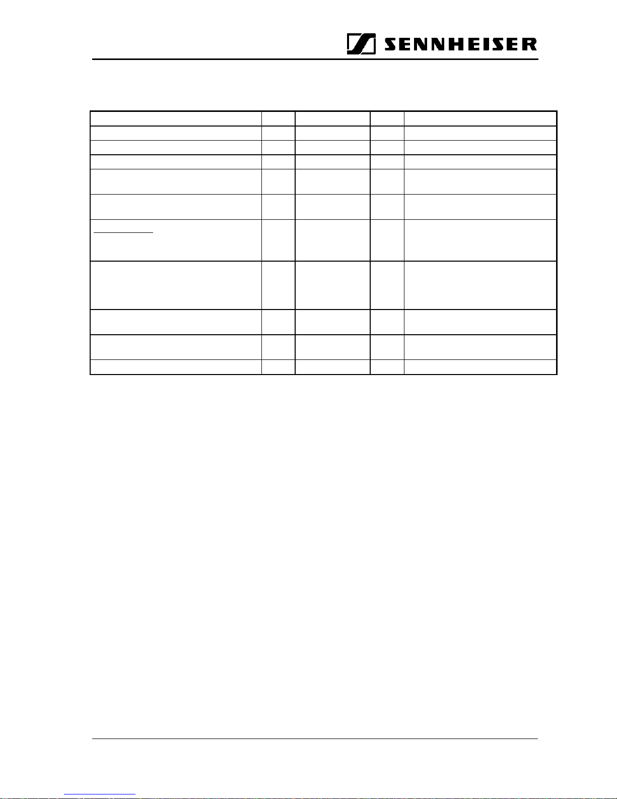
2.4.2 Technical Data
Transmission frequency f 127 kHz
Modulation type 2 - FSK
FM deviation 4 kHz
Data rate 8 kbit/s
Maximum transmission range with
internal antenna
3 m (isotropic pattern)
Maximum area covered by external
induction loop
9sq.m.
Power supply*
External DC
4 AA-size batteries
7.5–15
1.5
VVexternal power supply
inserted into identifier
Operating time with batteries
≥
3 months
P
out
= 100%,
T
on
= 8h/day
T
period
=1s
Programmable parameters ID code, RF output power, on/off
times, int./ext. antenna, burst rate
Setting of ID parameters via infrared data interface (IrDa)
with palmtop
Indoor operating temperature +10.........+50 °C
* N.B.: When the identifier is powered by an external DC supply, the battery supply will
be automatically cut off. We would recommend to use both external DC and batteries,
as this ensures that (a) no data will get lost in case of a mains power failure; (b) you
can conveniently program the battery-powered identifiers before they are mounted in
their final position and connected to an external DC supply.
Page 19

GuidePort: System Manual 27. November 2000 Seite 19
3 Software
3.1 Central Unit Software
The Central Unit Software runs on the Central Unit PC. It serves to configure the entire
GuidePort installation with its cells, transmitters, events and identifiers.
3.2 Cell Transmitter Loader Software
The Cell Transmitter Loader Software runs on the Base Stations. Via a USB, the
software detects the IDs of all Cell Transmitters connected to a Base Station. The Base
Station PCs transmit the configuration files – previously created by the Central Unit
Software–totheCellTransmitters.
 Loading...