

Page 1
Digital 6000
Instruction manual
Sennheiser electronic GmbH & Co. KG
Am Labor 1, 30900 Wedemark, Germany, www.sennheiser.com
Digital 6000 - v3.3
Page 2

The Digital 6000 Series 7
Features 8
Products in the Digital 6000 series 9
EM 6000 | EM 6000 DANTE 2-channel receiver 10
Package contents 10
Product overview 11
SKM 6000 handheld transmitter 12
Package contents 12
Product overview 13
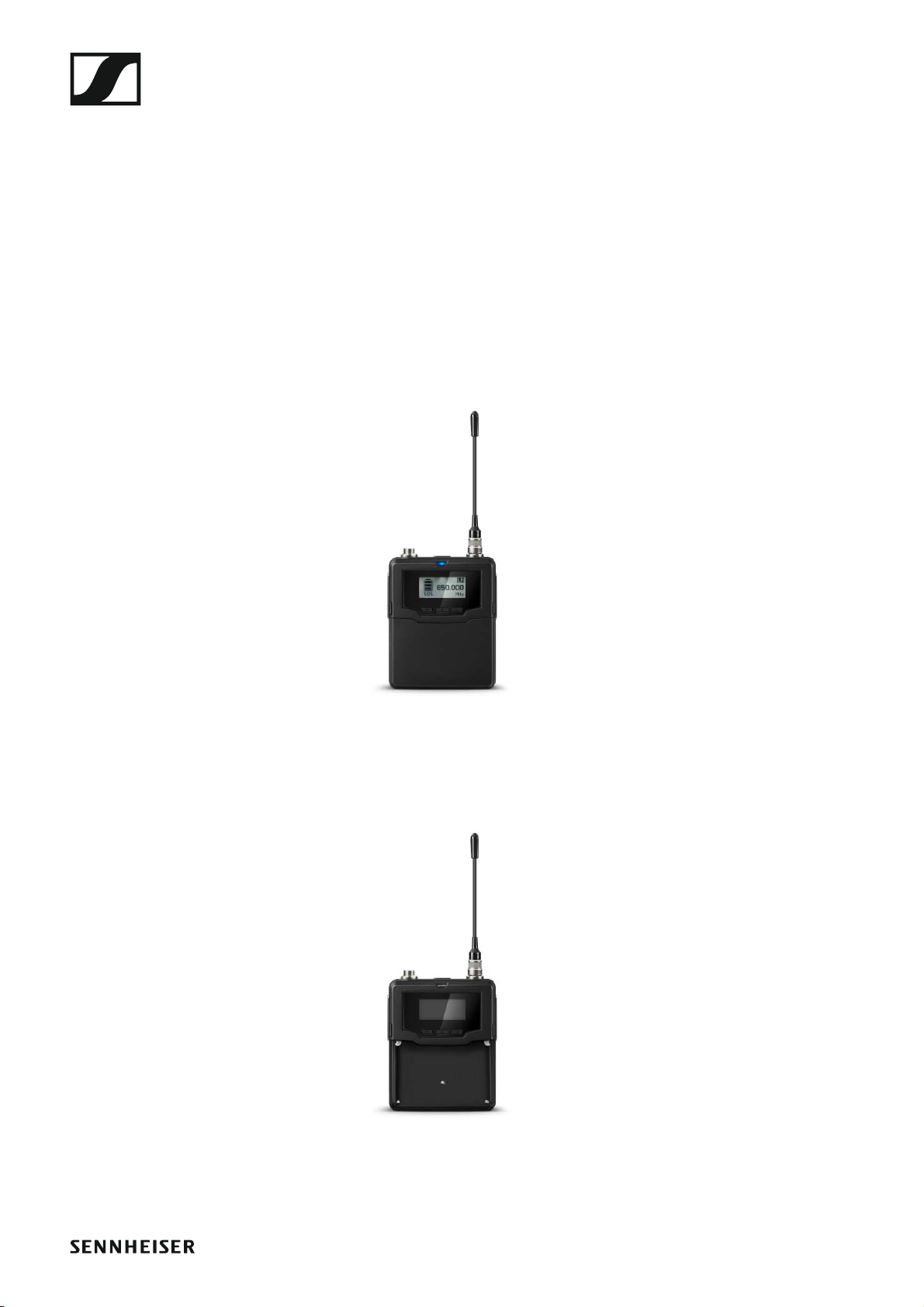
SK 6000 bodypack transmitter 14
Package contents 15
Product overview 15
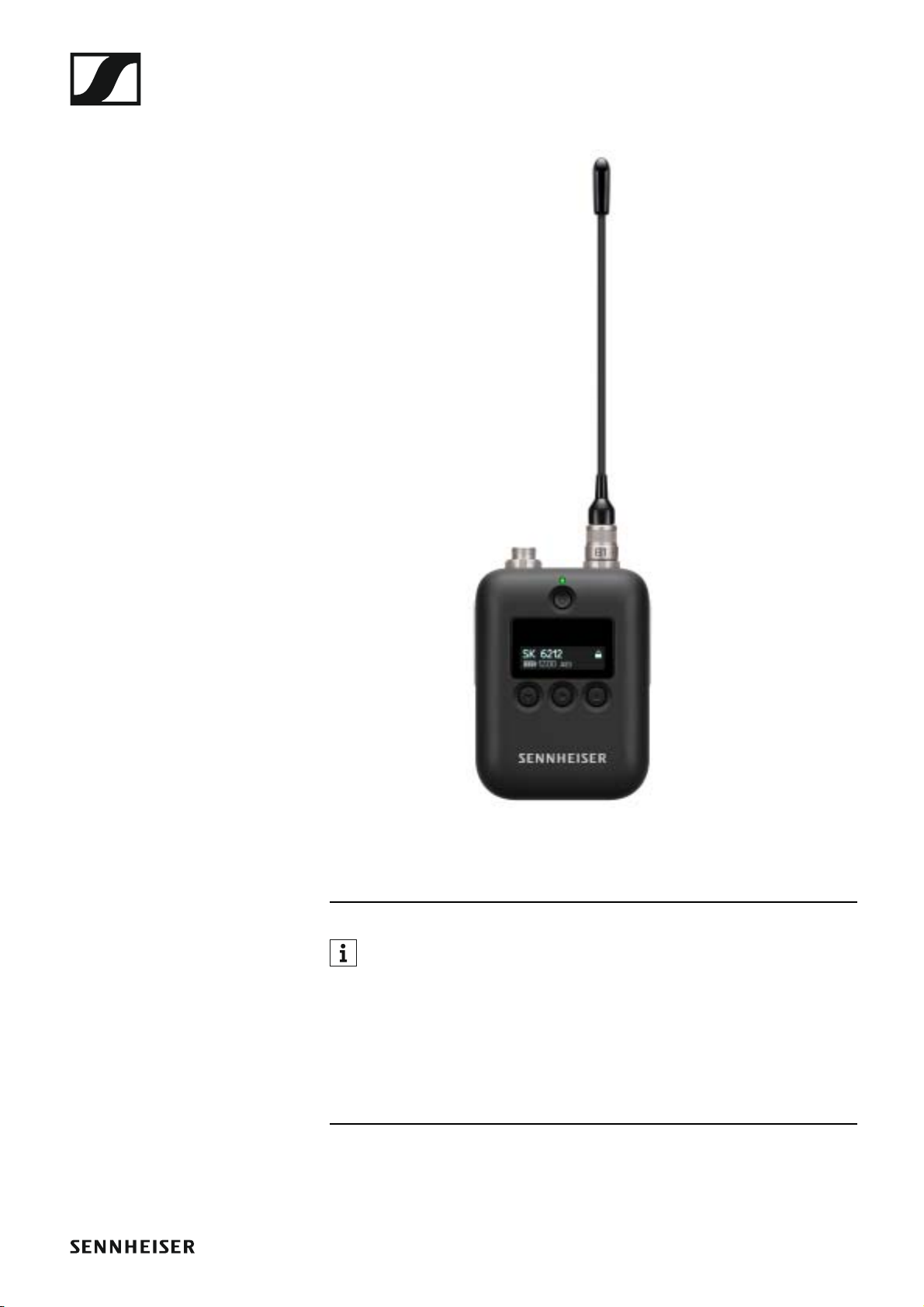
SK 6212 bodypack transmitter 16
Package contents 17
Product overview 17
Modular L 6000 charger 19
Package contents 19
Product overview 20
Accessories 21
Charging modules for L 6000 charger 21
LM 6060 21
LM 6061 21
LM 6062 22
Rechargeable batteries and battery compartments 23
BA 60 rechargeable battery 24
BA 61 rechargeable battery 24
BA 62 rechargeable battery 25
B 60 battery compartment 26
B 61 battery compartment 26
L 60 charger 27
Digital 9000 series handheld transmitter and bodypack
transmitter 28
SKM 9000 product variants 28
SK 9000 product variants 28
KA 9000 COM command adapter 29
Microphones and cables 30
Microphone modules 30
Headset and Lavalier microphones 31
Line/instrument cables 31
AES3 cable for digital audio signals 31
Antennas and accessories 32
Omni-directional antennas 32
Directional antennas 32
Circularly polarized antennas 32
Antenna splitter 32
Antenna amplifiers 32
Antenna cables 32
Antennas for bodypack transmitters 32
Installing Digital 6000 series devices 33
Installing the EM 6000 35
Connectors on the rear of the device 35
1
Page 3

Product overview for the rear side of the EM 6000 35
Product overview for the rear side of the EM 6000 DAN-
TE 36
Connecting/disconnecting the EM 6000 to/from the power supply system 37
Connecting the EM 6000 to a network 38
Outputting analog audio signals 39
Outputting digital audio signals 40
Outputting audio via a Dante™ network (EM 6000 DANTE
only) 41
Connecting the word clock 42
Connecting remote antennas 44
Cascading receivers 45
Connecting rod antennas 46
Installing the EM 6000 in a rack 47
Installing the SKM 6000 48
Inserting and removing the BA 60 rechargeable battery
49
Inserting and removing the B 60 battery compartment 51
Replacing the microphone module 53
Installing the SK 6000 55
Inserting and removing the BA 61 rechargeable battery
56
Inserting and removing the B 61 battery compartment 58
Mounting the antenna 60
Connecting a microphone to the SK 6000 61
Connecting an instrument or line source to the SK 6000
62
Connecting the KA 9000 COM command adapter to the
SK 6000 63
Installing the SK 6212 64
Inserting and removing the BA 62 rechargeable battery
64
Mounting the antenna 66
Connecting a microphone to the SK 6212 68
Connecting an instrument or line source to the SK 6212
70
Installing the L 6000 | LM 6060 | LM 6061 | LM 6062
71
Connecting/disconnecting the L 6000 to/from the power supply system 71
Connecting the L 6000 to a network 72
Installing the LM 6060, LM 6061 and LM 6062 charging
modules in the L 6000 73
Installing the L 6000 in a rack 75
Using Digital 6000 series devices 76
Using the EM 6000 78
Operating elements on the front of the device 78
Product overview for the front of the EM 6000 78
Switching the EM 6000 on and off 80
2
Page 4

Displays on the EM 6000 display panel 81
Buttons for navigating through the menu 83
Home screen 84
Home screen 1 84
Home screen 2 86
Home screen 3 87
Home screen 4 88
Home screen 5 (audio mute) 88
Muting the audio signal 89
Setting options in the menu 90
Menu structure 92
Frequency menu item 93
Name menu item 95
Sync Settings menu item 96
Gain 99
Low Cut 100
Auto Lock 100
Display panel 101
Cable 101
Power LED Mode 102
MIC Line Mode 102
Frequency Only 103
Encryption menu item 104
Command Mode menu item 106
EXAMPLE: 107
Scan & Auto-Setup menu item 108
Performing a frequency scan and automatic frequency
setup 108
Step 1a: New Scan 110
Step 1b: Use Old Scan 112
Step 2: Editing displayed frequencies 112
Step 3: Starting the automatic frequency setup 114
Walktest menu item 116
AF Output menu item 118
Test Tone menu item 119
Bank Edit menu item 120
System menu item 122
System -> Wordclock menu item 125
System -> Network menu item 126
System -> Device ID menu item 128
System -> Dante Settings (only EM 6000 DANTE) menu
item 129
Device ID 129
Mode 130
PrimNet 131
SecNet 132
Info 132
System -> Booster Feed menu item 133
System -> Brightness menu item 134
System -> Auto Setup menu item 135
System -> Info menu item 136
System -> Hardware menu item 136
3
Page 5

System -> Help menu item 137
System -> TX Update menu item 137
System -> Reset menu item 138
Using the headphone output 139
Updating the firmware of the receiver 140
Updating the firmware of the Dante™ interface 141
Status messages 142
Using the SKM 6000 145
Operating elements of the SKM 6000 handheld transmitter 145
Switching the SKM 6000 on and off 146
Displays on the SKM 6000 handheld transmitter display
panel 147
Operating the SKM 6000 menu 148
Navigating through the menu 148
Making changes in a menu item 148
Menu item overview 148
Updating the firmware of the SKM 6000 151
Using the SK 6000 152
Operating elements of the SK 6000 bodypack transmitter 153
Switching the SK 6000 on and off 154
Displays on the SK 6000 bodypack transmitter display
panel 155
Operating the SK 6000 menu 156
Navigating through the menu 156
Making changes in a menu item 156
Menu item overview 156
Operating the SK 6000 with the KA 9000 COM command
adapter 160
Updating the firmware of the SK 6000 160
Using the SK 6212 161
Operating elements of the SK 6212 bodypack transmitter
161
Switching the SK 6212 on and off 162
Switching on the SK 6212 bodypack transmitter 162
Switching on the SK 6212 bodypack transmitter and
deactivating the RF signal 162
Switching off the SK 6212 bodypack transmitter 162
Home screen 163
Home screen 1: Frequency 163
Home screen 2: Name 163
Home screen 3: Audio 164
Displays on the SK 6212 bodypack transmitter display
164
Operating the SK 6212 menu 165
Navigating through the menu 165
Making changes in a menu item 165
Menu item overview 165
Updating the firmware of the SK 6212 168
Using the L 6000 169
4
Page 6

Switching the L 6000 on and off 169
Charging rechargeable batteries 170
Meaning of the LEDs on the L 6000 charger and
LM 6060, LM 6061 and LM 6062 charging modules 172
L 6000 status LEDs 172
LM 6060, LM 6061 and LM 6062 status LEDs 173
LM 6060, LM 6061 and LM 6062 status LEDs in stora-
ge mode 173
Preparing rechargeable batteries for storage (storage
mode) 174
Meaning of the status LEDs in storage mode 174
Resetting settings (factory reset) 175
Updating the firmware 175
Operating the L 6000 via a network 176
Establishing a radio link 177
Adjusting frequencies 177
Encrypting the radio link 177
Meaning of the Link Quality Indicator 177
Green range from 50% to 100%: 178
Yellow range from 20% to 49%: 178
Orange range from 1% to 19%: 178
Red range 0%: 178
Synchronizing devices 179
Overview 180
Recommendations for using antennas 181
Rod antennas (included in the delivery) 181
Remote antennas 181
Active vs passive antennas 181
General recommendation 181
Types of remote antenna 182
Losses due to cable properties and length 182
Equidistant frequency grid 183
Word clock scenarios for digital audio (AES3 and
Dante™) 184
Word clock with analog audio 184
Word clock with digital audio 184
Defining the master and slave 185
Overview 186
Product variants 186
EM 6000 | EM 6000 DANTE product variants 186
SKM 6000 product variants 187
SK 6000 product variants 187
SK 6212 product variants 188
L 6000 product variants 188
LM 6060, LM 6061 and LM 6062 product variants 188
Specifications 189
System 189
EM 6000 189
EM 6000 DANTE 190
SKM 6000 192
5
Page 7

SK 6000 193
SK 6212 194
L 6000 195
LM 6060 | LM 6061 | LM 6062 196
BA 60 | BA 61 | BA 62 196
Cleaning and maintenance 197
Cleaning the sound inlet basket of the microphone mo-
dule 197
Cleaning the SK 6000 bodypack transmitter contacts.
198
Cleaning the L 6000 charger 198
6
Page 8
The Digital 6000 Series
PRODUCT INFORMATION
The Digital 6000 Series
For more information about the individual products in the Digital 6000 series, see „Products in the Digital 6000 series“.
For information about the available accessories, see „Accessories“.
►
When perfection is required there can be no compromises. The Digital
6000 system combines experience, high standards and excellent instincts
for day-to-day work in the modern live event industry into one simple
promise: no compromises in RF robustness, sound or workflow.
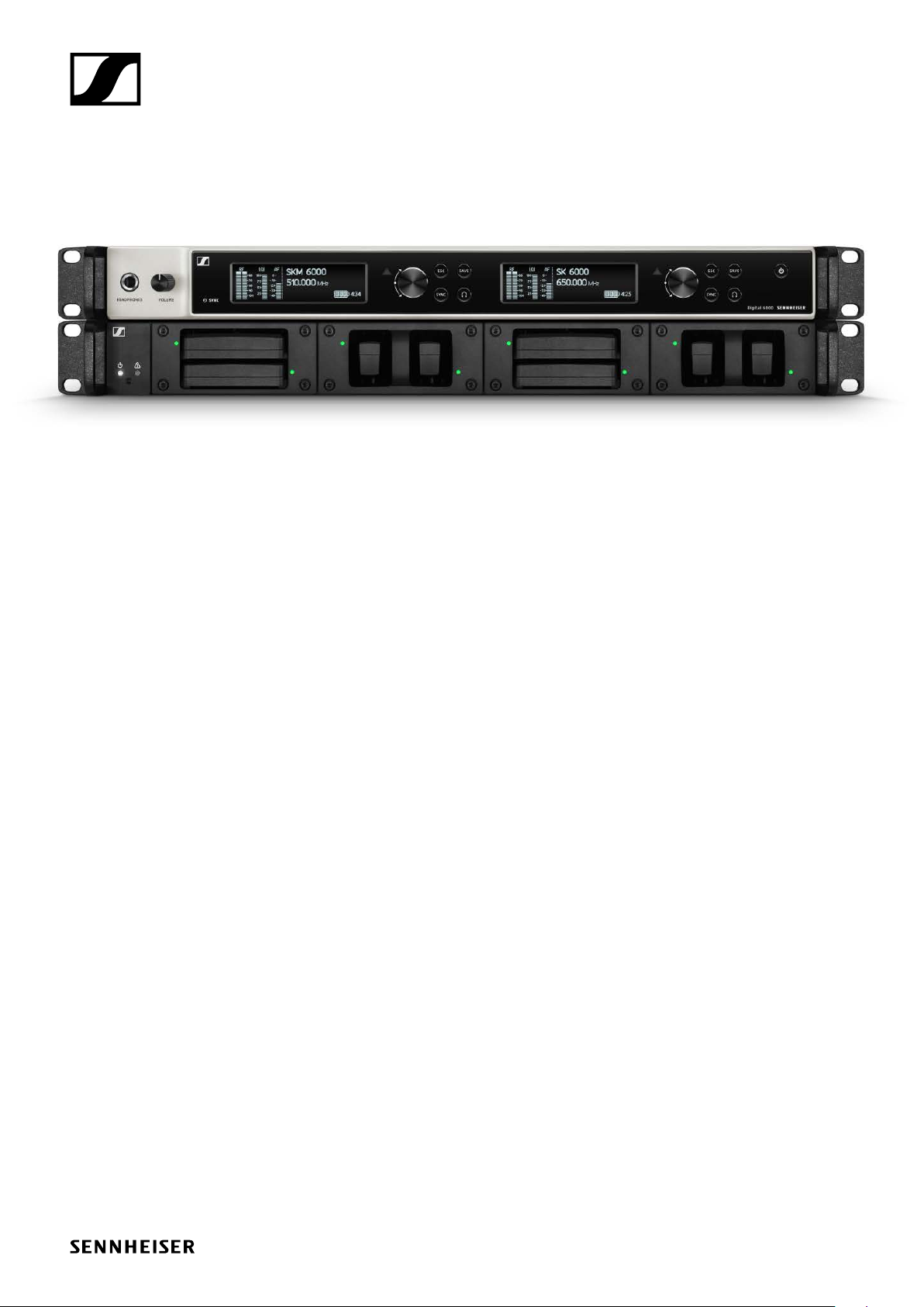
The 2-channel system delivers quality, reliability and efficiency in a compact 19-inch/1 RU format. The series incorporates the renowned Long
Range mode with the proprietary audio codec (SeDAC) of the wireless
masterpiece, Digital 9000.
True bit diversity evaluates the quality of each individual bit and combines
the bits from the two parallel reception streams. In combination with a
switching bandwidth of 244 MHz and equidistant frequency grid, it provides the greatest possible transmission reliability even in demanding RF
environments. Digital 6000 is compatible with many other Sennheiser antennas and capsules and has an easy-to-follow user interface on clear
OLED displays, digital and analog outputs and AES 256 encryption. The
Dante Version with an Audinate Brooklyn II Card offers an additional RJ-45
connector.
The series is ideal for touring and rental companies, theater and musical
productions, broadcasting, large places of worship and corporate applications.
7
Page 9

The Digital 6000 Series
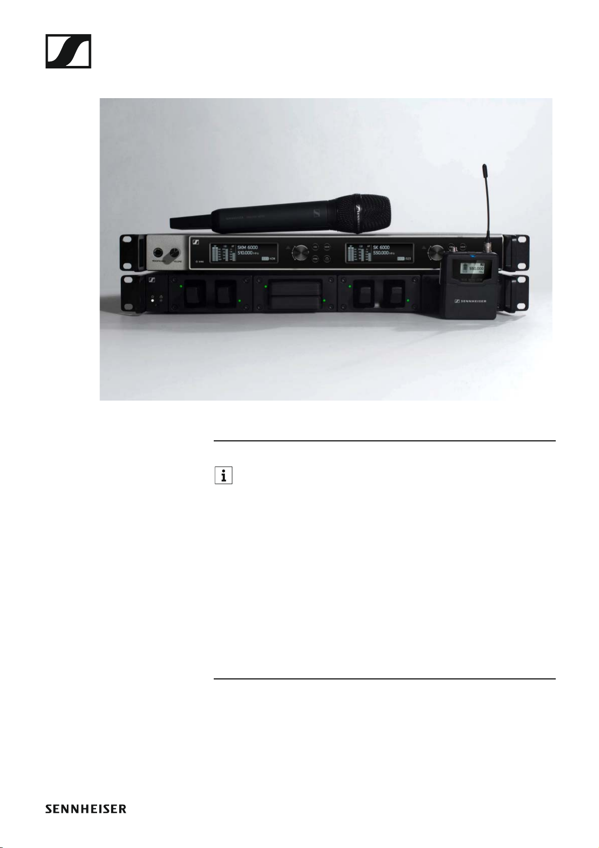
The 6000 series includes a 2-channel receiver, a bodypack transmitter, a
handheld transmitter and a modular 19-inch rack-mounted charger.
Digital 6000 combines the benefits of modern audio technology with an intelligent operating concept. The frequency range can be scanned directly
with the receiver, which then distributes free frequencies within the network. The equipment can also be monitored and configured via Wireless
System Manager (WSM) software. The high-quality OLED display provides
an overview with a multitude of operating data. Intelligent home screens
lead you directly to important contextual information with no need for timeconsuming navigation. In addition to the popular RF graphs, the link quality
display (LQI) allows a real-time evaluation of the wireless link quality. That
allows you to identify and eliminate risks immediately.
Digital 6000 integrates seamlessly into existing digital and analog infrastructures. The EM 6000 receiver has a digital AES3 output with word
clock inputs and outputs, high-quality transformer-balanced analog XLR-3
outputs, 6.3 mm (1/4") jack outputs and a 6.3 mm (1/4") headphone output.
The Dante version with an Audinate Brooklyn II card offers an additional
Amphenol RJ-45 jack plug for integrating the receiver into a Dante network.
The Digital 6000 series includes a 2-channel receiver available in 2 versions, a bodypack transmitter, a handheld transmitter and a modular 19inch rack-mounted charger.
Features
• A 2-channel receiver in a compact 19-inch/1 RU format combines performance, efficiency and clarity
• The wireless transmission uses the legendary Long Range mode with
SeDAC codec from the masterpiece, Digital 9000 – for maximum transmission quality
• True bit diversity, error correction and masking protect the transmission channels even in demanding RF environments
• Future-proof and usable worldwide thanks to the large 244 MHz switching bandwidth
• The equidistant frequency grid guarantees the highest possible number
of channels and simplest configuration, even in the most congested frequency bandwidths.
• Sophisticated transmitter electronics prevent disruptive intermodulation even with multiple transmitters in confined spaces
• Low system latency of just 3 ms
• Multiple outputs for analog and digital systems (XLR, jack socket, AES,
Dante (EM 6000 Dante only))
• AES 256 encryption for maximum data security
• Simple setup of multi-channel solutions: With the integrated antenna
splitters, you can cascade up to 8 receivers without any additional hardware
• Compatible with a huge number of Sennheiser and Neumann capsules,
Lavalier microphones (clip-on microphones), headsets and antenna
systems
• High-resolution white OLED display with four easy access home
screens
• Simple, intuitive user concept for setup and monitoring
•WSM-compatible
• Transmitter equipped with lithium-ion rechargeable batteries
• Modular 19 inch/1 RU charger
8
Page 10
Products in the Digital 6000 series
Products in the Digital 6000 series
►
You can also find more information here:
▷ A variety of frequency variants are available for the SKM 6000,
SK 6000 and SK 6212 transmitters. You can find more information under „Product variants“.
▷ You can find technical specifications about the individual products un-
der „Specifications“.
▷ You can find information about installing the products under „Install-
ing Digital 6000 series devices“.
▷ You can find information about operating the products under „Using
Digital 6000 series devices“.
9
Page 11
Products in the Digital 6000 series
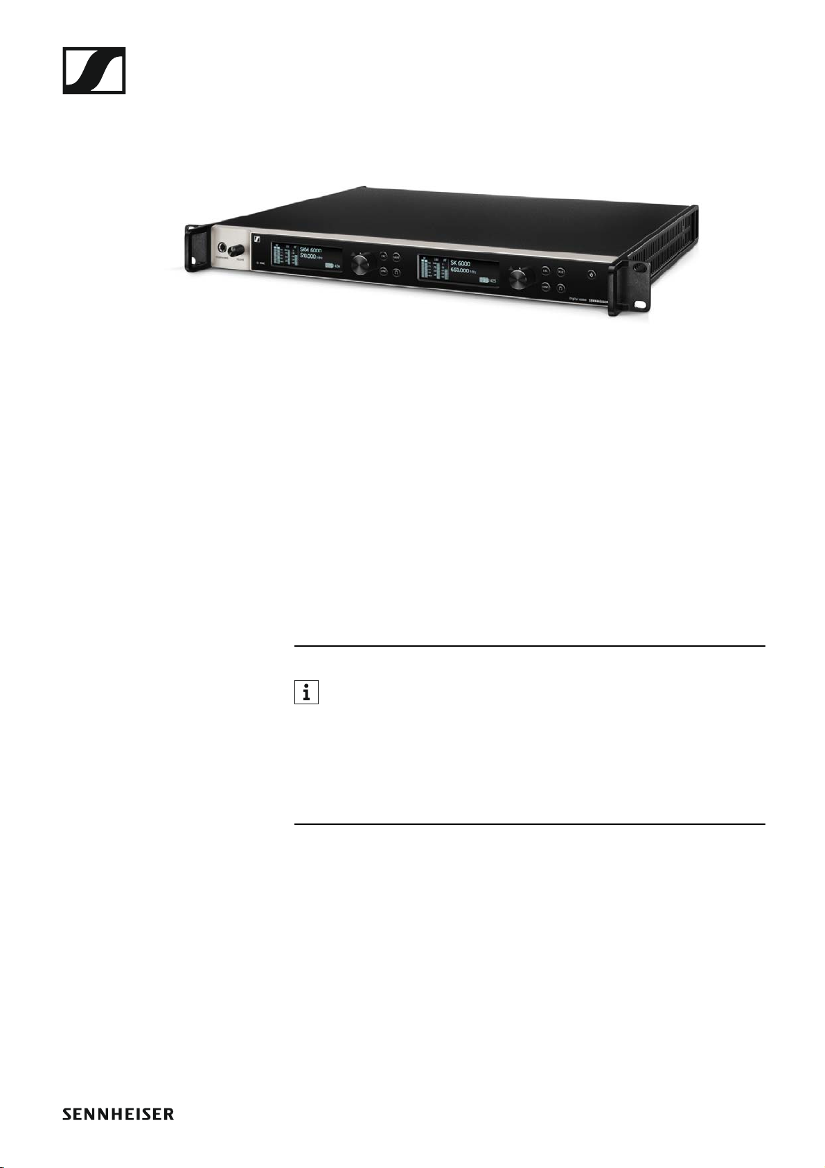
EM 6000 | EM 6000 DANTE 2-channel receiver
►
The digital 2-channel receiver works with a switching bandwidth of
244 MHz (470 to 714 MHz), which is covered by three transmitter versions.
For larger 4-channel systems, you can cascade up to EM 6000s without using additional antenna splitters and you then require only one pair of antennas.
The 2-channel receiver is available in 2 variants:
• EM 6000
• EM 6000 DANTE
The EM 6000 DANTE variant is identical in construction to the EM 6000.
The only difference is that it also has an integrated Dante™ interface (Audinate Brooklyn II) for connecting the device to a Dante™ network. Two
modes are supported for the two Dante™ sockets: Redundant and Through.
▷ See „EM 6000 | EM 6000 DANTE product variants“
You can find more detailed information about the EM 6000 in the following sections:
▷ Installation: „Installing the EM 6000“
▷ Operation: „Using the EM 6000“
▷ Specifications: „EM 6000“ or „EM 6000 DANTE“
Package contents
• 1 EM 6000 or EM 6000 DANTE 2-channel receiver
• 1 mains cables (EU, UK, or US variant)
•2 antennas
• 2 antenna cables (BNC, 50 Ω)
• 4 rubber feet
•1 quick guide
• 1 manual with safety instructions
• 1 manual with technical data and manufacturer declarations
10
Page 12
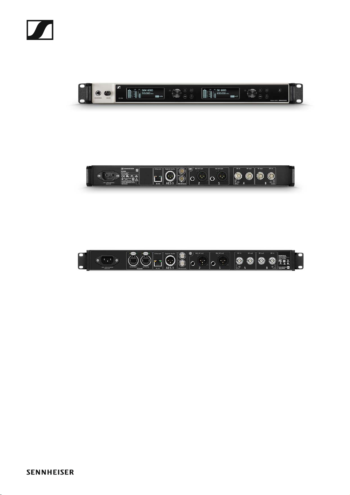
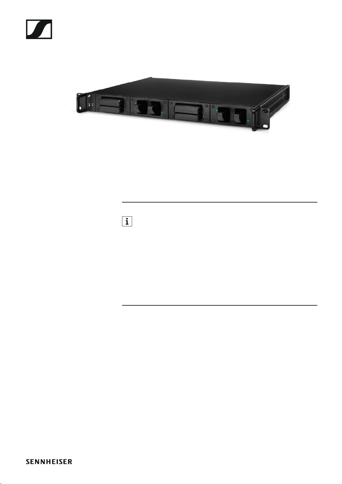
Product overview
View of the front side:
►
Rear view of the EM 6000:
►
Products in the Digital 6000 series
Rear view of the EM 6000 DANTE:
►
11
Page 13
Products in the Digital 6000 series
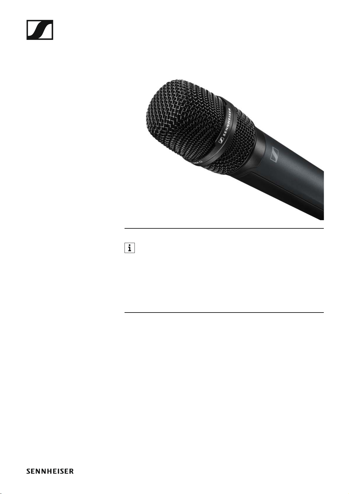
SKM 6000 handheld transmitter
►
You can find more detailed information about the SKM 6000 in the following sections:
▷ Installation: „Installing the SKM 6000“
▷ Operation: „Using the SKM 6000“
▷ Frequency variants: „SKM 6000 product variants“
▷ Specifications: „SKM 6000“
Package contents
• 1 SKM 6000 handheld transmitter
• 1 MZQ 9000 microphone clamp
•1 quick guide
• 1 manual with safety instructions
• 1 manual with technical data and manufacturer declarations
12
Page 14
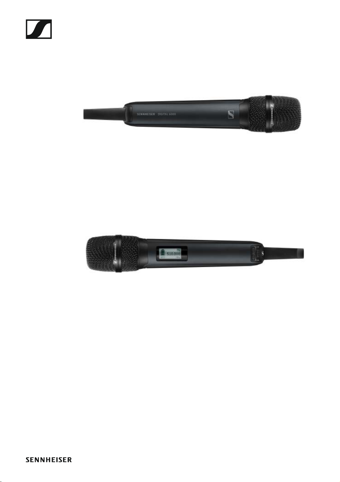
Product overview
View of the front side:
►
Products in the Digital 6000 series
View of the rear side with the display:
►
13
Page 15
Products in the Digital 6000 series
SK 6000 bodypack transmitter
►
You can find more detailed information about the SK 6000 in the following sections:
▷ Installation: „Installing the SK 6000“
▷ Operation: „Using the SK 6000“
▷ Frequency variants: „SK 6000 product variants“
▷ Specifications: „SK 6000“
14
Page 16
Products in the Digital 6000 series
Package contents
• 1 SK 6000 bodypack transmitter
• 1 antenna
•1 belt clip
•1 quick guide
• 1 manual with safety instructions
• 1 manual with technical data and manufacturer declarations
Product overview
View of the front side:
►
View without rechargeable battery:
►
15
Page 17
Products in the Digital 6000 series
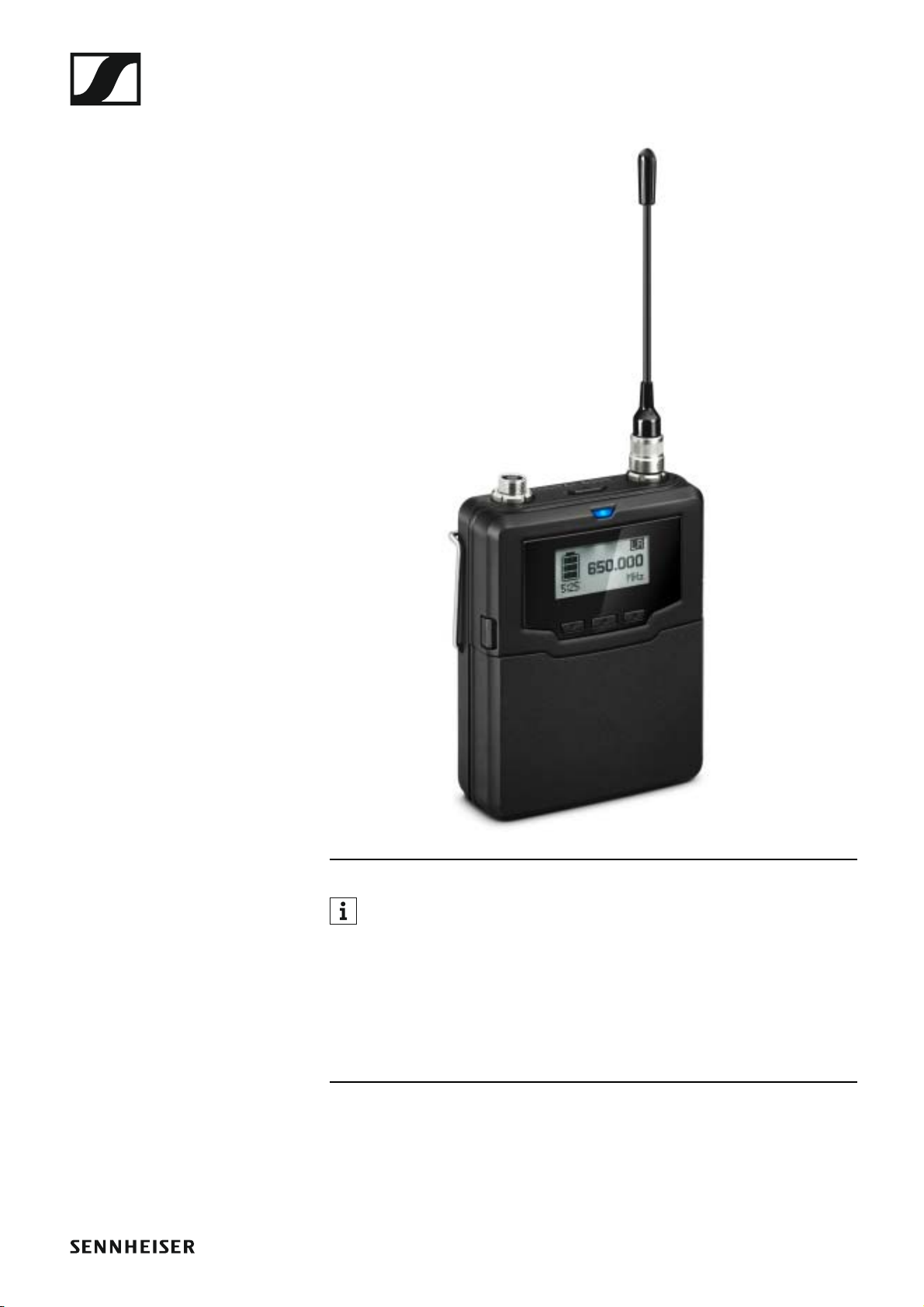
SK 6212 bodypack transmitter
►
You can find more detailed information about the SK 6212 in the following sections:
▷ Installation: „Installing the SK 6212“
▷ Operation: „Using the SK 6212“
▷ Frequency variants: „SKM 6000 product variants“
▷ Specifications: „SK 6212“
16
Page 18
Products in the Digital 6000 series
Package contents
• 1 SK 6212 bodypack transmitter
• 1 antenna
•1 belt clip
•1 quick guide
• 1 supplement sheet with safety instructions
• 1 supplement sheet with specifications and manufacturer declarations
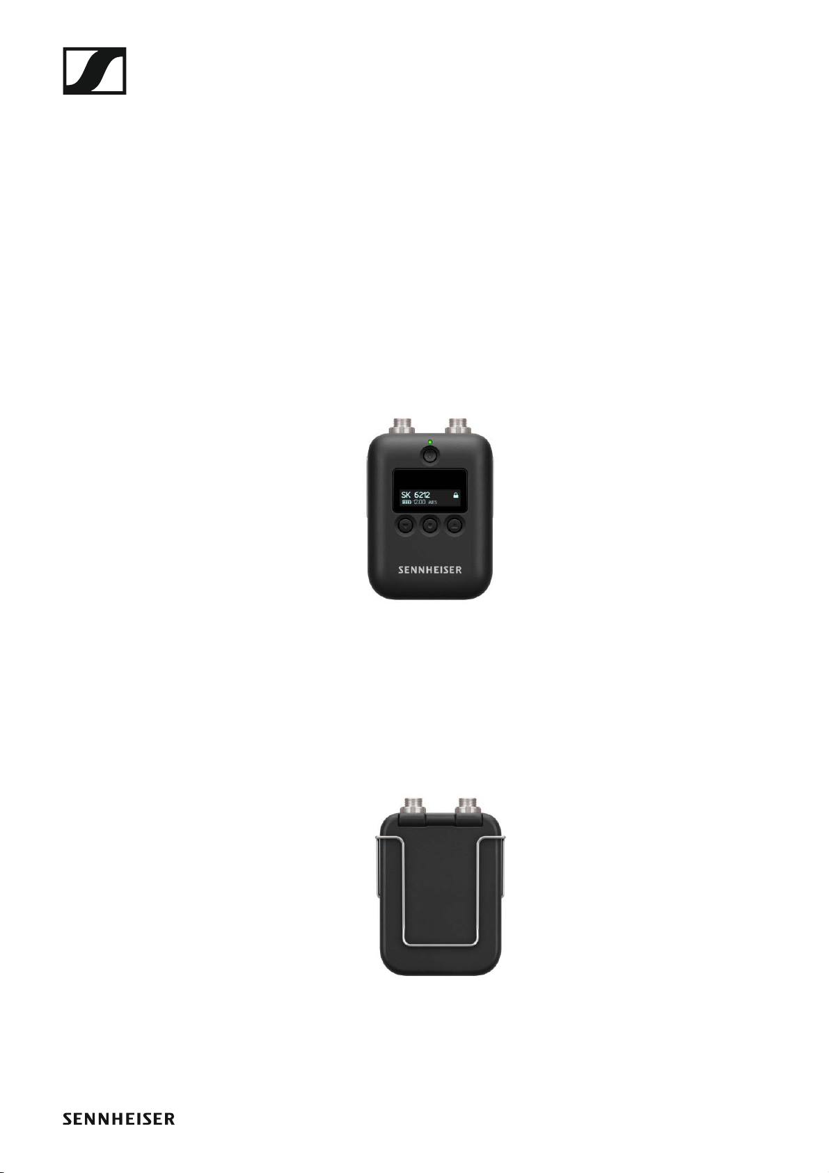
Product overview
View of the front side:
►
View of the rear side:
►
17
Page 19
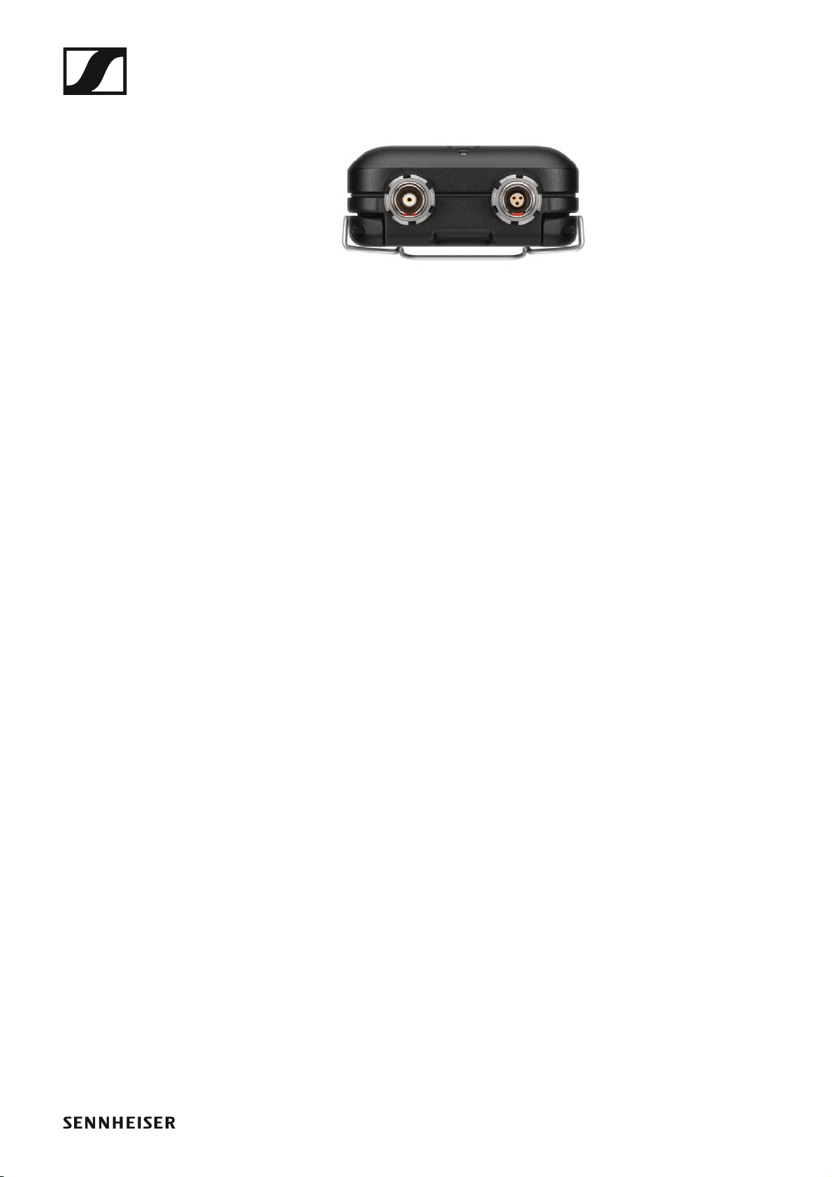
View from above:
►
Products in the Digital 6000 series
18
Page 20
Products in the Digital 6000 series
Modular L 6000 charger
►
The L 6000 charger is used to charge the BA 60, BA 61 and BA 62 rechargeable batteries. The charging modules LM 6060 (for the BA 60),
LM 6061 (for the BA 61) or LM 6062 (for the BA 62) are required to do so.
The rechargeable batteries and charging modules are available separately.
You can find more detailed information about the L 6000 charger and
the LM 6060, LM 6061 and LM 6062 charging modules in the following
sections:
▷ Information about the rechargeable batteries and charging mod-
ules: „Rechargeable batteries and battery compartments“ and
„Charging modules for L 6000 charger“
▷ Installation: „Installing the L 6000 | LM 6060 | LM 6061 | LM 6062“
▷ Operation: „Using the L 6000“
▷ Specifications: „L 6000“ or „LM 6060 | LM 6061 | LM 6062“
Package contents
• 1 L 6000 charger
• 1 mains cables (EU, UK, or US variant)
• 4 dummy caps including screws (preassembled)
• 4 rubber feet
•1 quick guide
• 1 manual with safety instructions
• 1 manual with technical data and manufacturer declarations
19
Page 21
Products in the Digital 6000 series
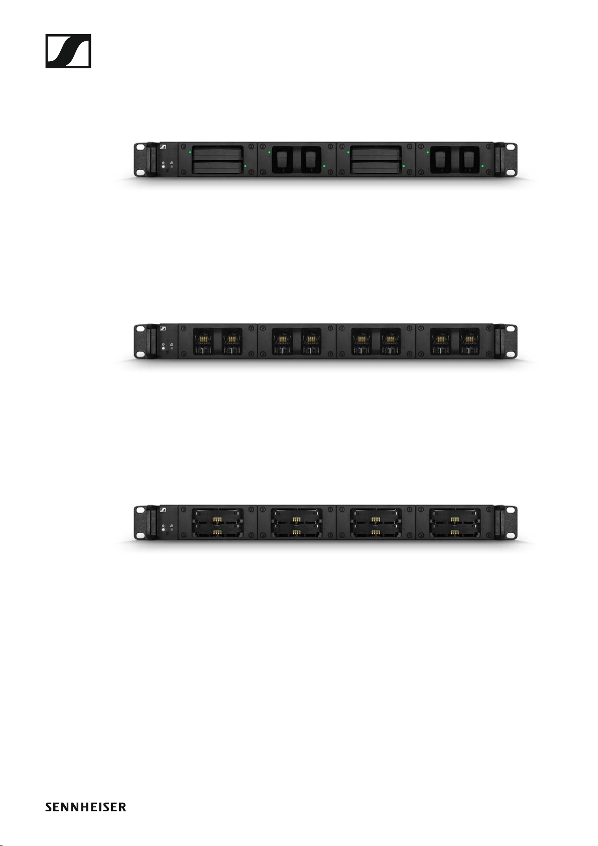
Product overview
View with the charging modules and rechargeable batteries inserted:
►
View with the LM 6060 charging modules without rechargeable batteries inserted:
►
View with the LM 6061 charging modules without rechargeable batteries inserted:
►
20
Page 22
Accessories
Accessories
Various accessory parts are available for the Digital 6000 series.
Charging modules for L 6000 charger
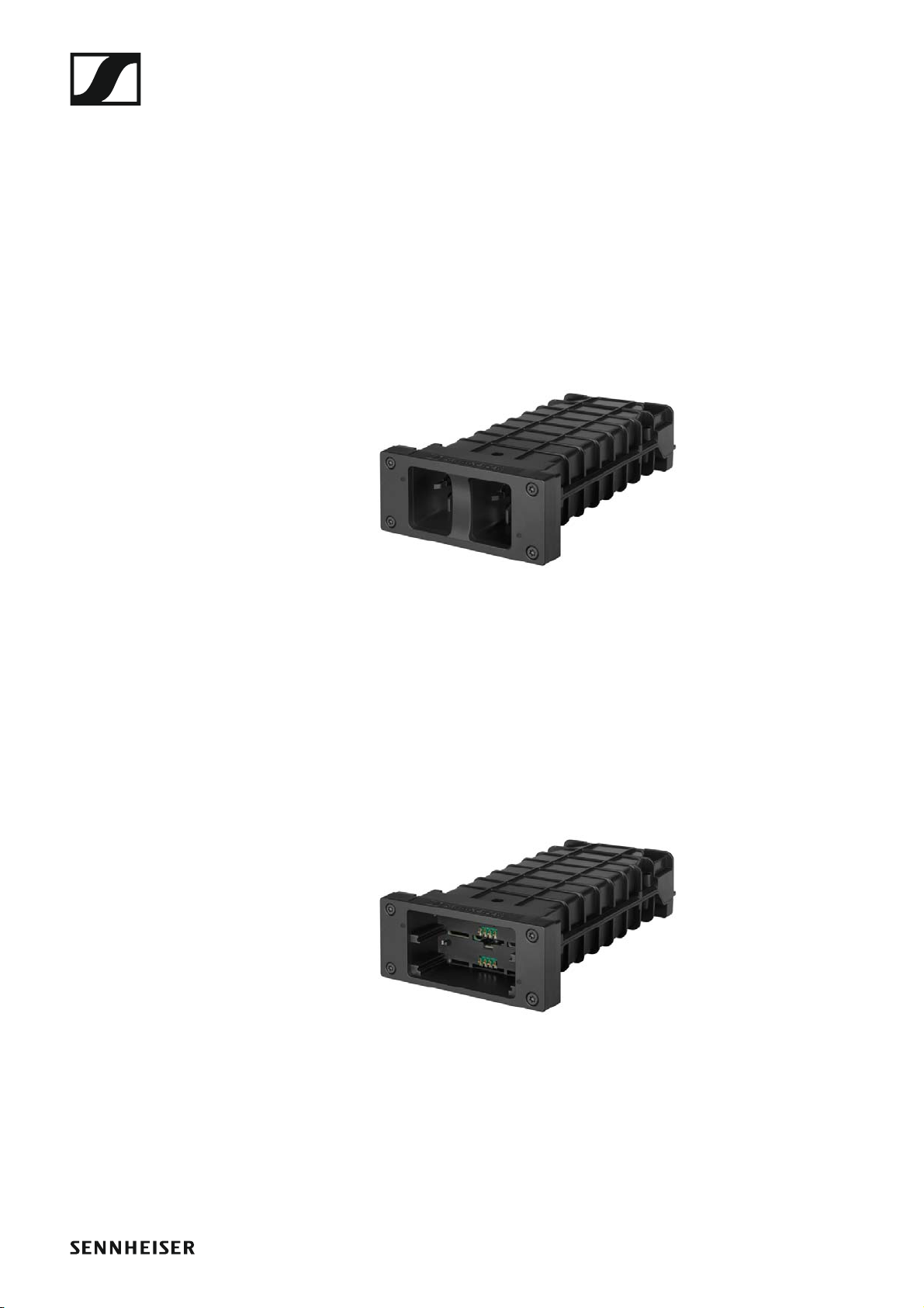
LM 6060
The LM 6060 charging module is installed in the L 6000 charger to charge
the BA 60 rechargeable battery.
4 Torx 10 screws for mounting in the L 6000 are included in the delivery.
►
Sennheiser article number 507198
LM 6061
The LM 6061 charging module is installed in the L 6000 charger to charge
the BA 61 rechargeable battery.
4 Torx 10 screws for mounting in the L 6000 are included in the delivery.
►
Sennheiser article number 507199
21
Page 23
Accessories
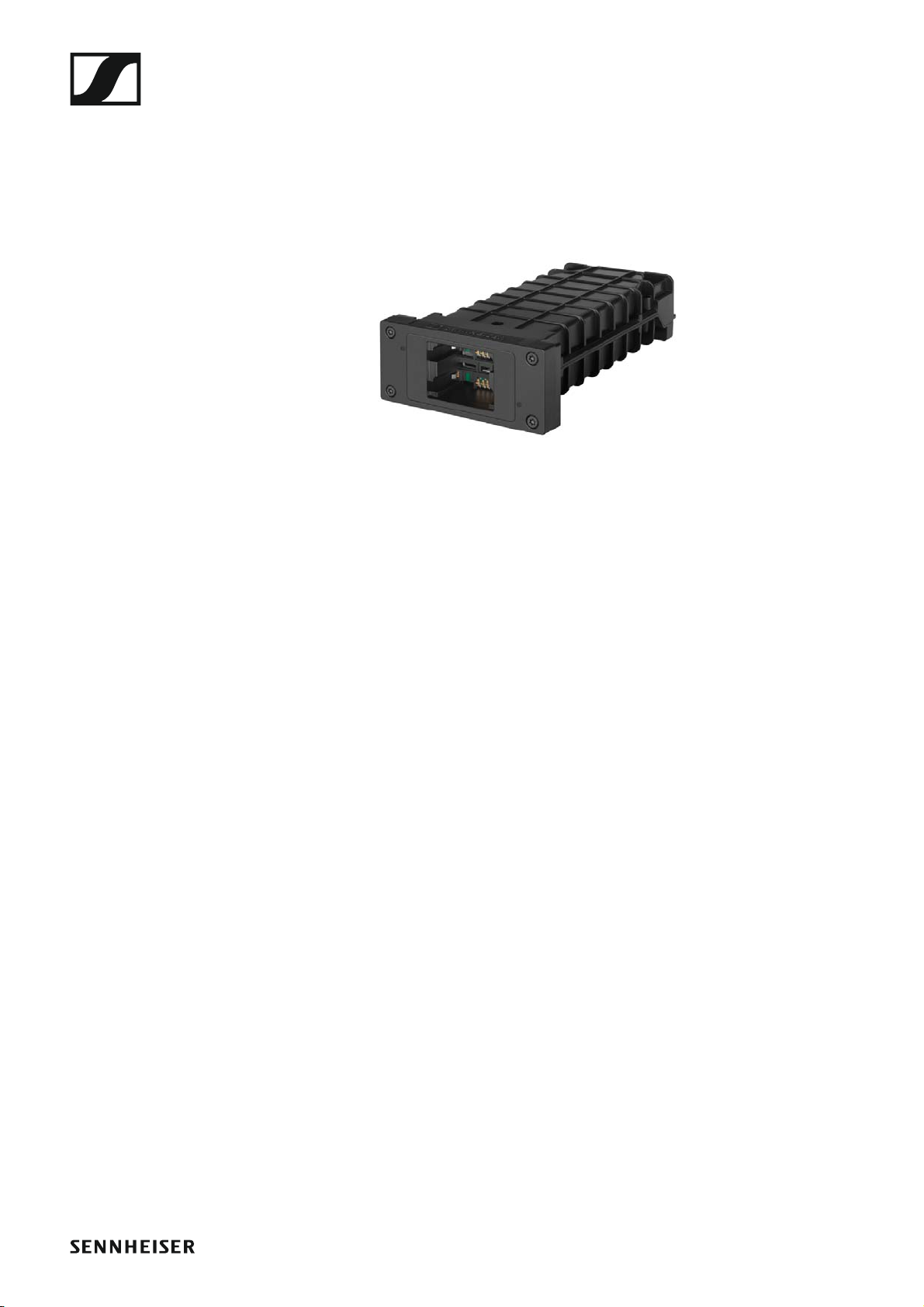
LM 6062
The LM 6062 charging module is installed in the L 6000 charger to charge
the BA 62 rechargeable battery.
4 Torx 10 screws for mounting in the L 6000 are included in the delivery.
►
Sennheiser article number 508516
22
Page 24

Accessories
Rechargeable batteries and battery compartments
Rechargeable batteries:
To operate the transmitters, we recommend using the rechargeable batteries BA 60 (for the SKM 6000 handheld transmitter), BA 61 (for the
SK 6000 bodypack transmitter) or BA 62 (for the SK 6212 bodypack transmitter). The rechargeable batteries are available as accessories. These
lithium-ion rechargeable batteries have been especially developed to
achieve the optimum service life and operational reliability for the transmitters.
Lithium-ion rechargeable batteries do not have a memory effect and have
a greater power density than primary batteries and NiMh rechargeable
batteries. In addition, the remaining battery life of the transmitters can be
read to the exact minute on the transmitter and receiver.
These rechargeable batteries must be charged only with Sennheiser
L 6000 (BA 60, BA 61 and BA 62) and L60 (BA 60 and BA 61) chargers.
Battery compartments:
With the B60 battery compartment (for the SKM 6000 handheld transmit-
ter) and B61 battery compartment (for the SK 6000 bodypack transmitter)
that are also available as accessories, you can use AA batteries and rechargeable AA batteries. However, the battery life of the transmitters is
shorter than the BA 60 and BA 61 rechargeable battery life and depends
heavily on the quality, capacitance and age of the batteries or rechargeable
batteries used.
The remaining battery life can only be roughly estimated from the battery
icon and a specific battery life cannot be displayed. At the end of the battery life, the transmitters may also experience oscillating on-off switching
behavior.
The use of battery compartments may be a solution for rehearsals or to
avoid disasters, but should generally not be considered as part of an event.
23
Page 25
Accessories
BA 60 rechargeable battery
The BA 60 rechargeable battery is intended to operate the SKM 6000
handheld transmitter.
►
Sennheiser article number 504702
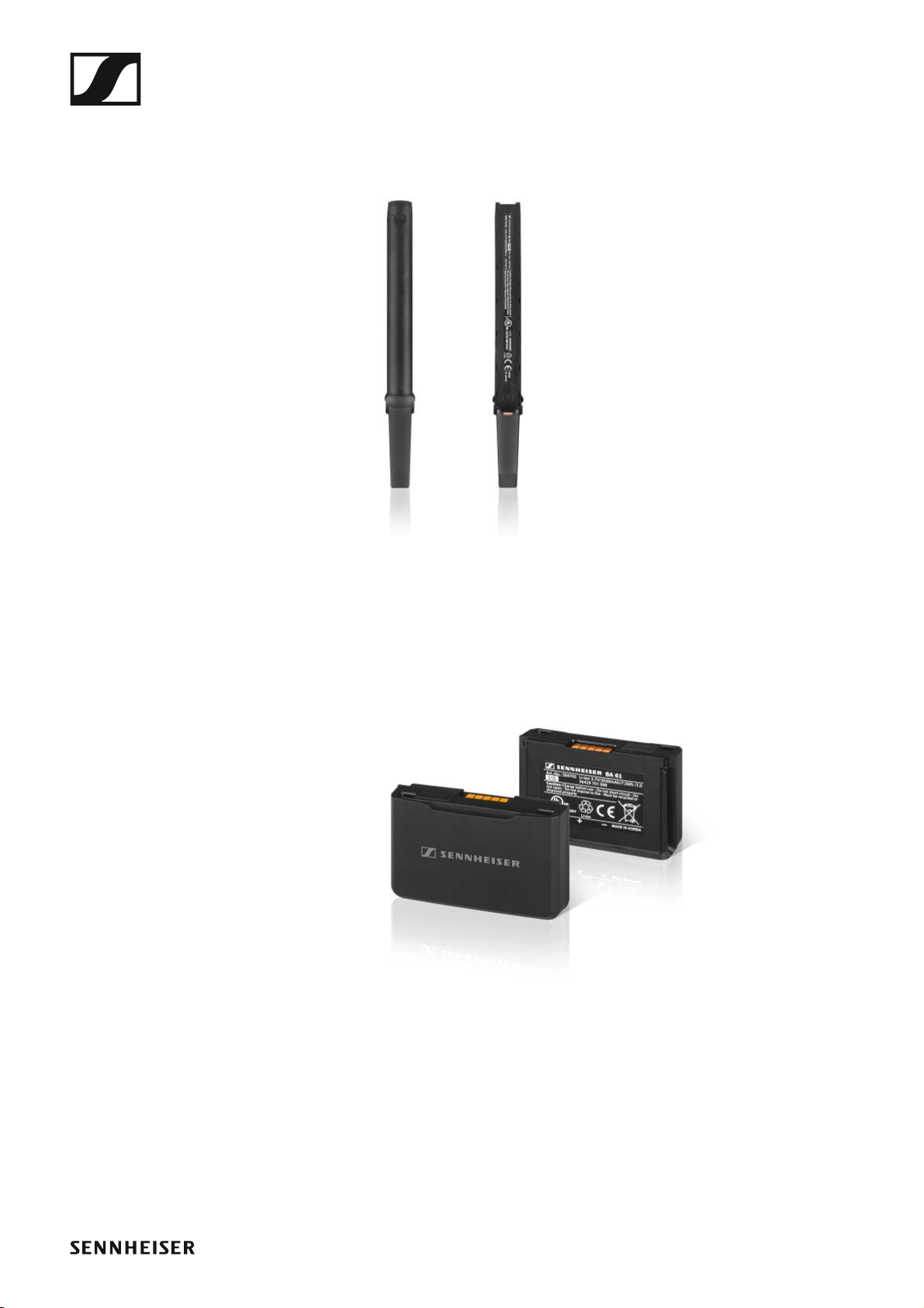
BA 61 rechargeable battery
The BA 61 rechargeable battery is intended to operate the SK 6000
bodypack transmitter.
►
Sennheiser article number 504703
24
Page 26
Accessories
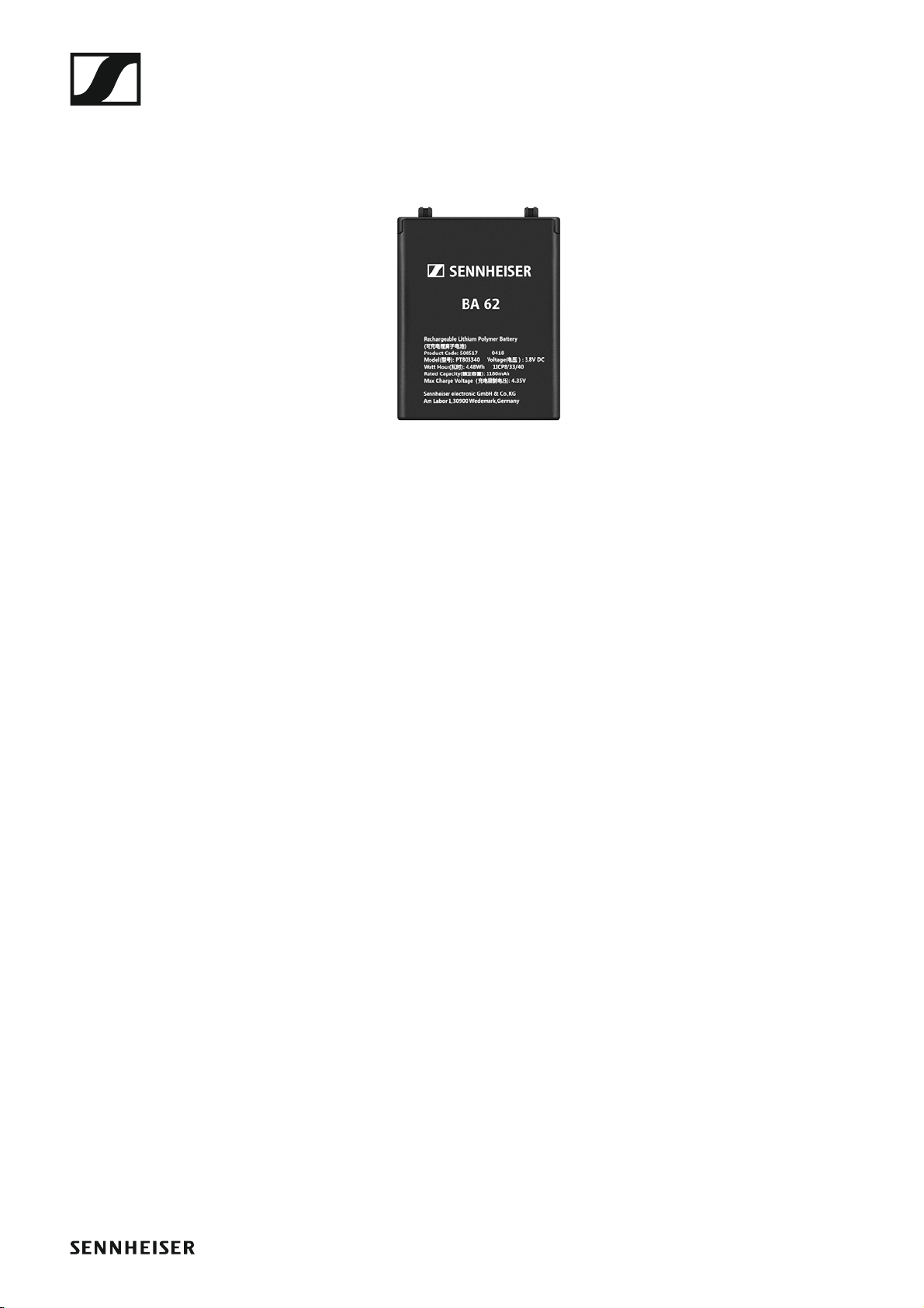
BA 62 rechargeable battery
The BA 62 rechargeable battery is intended to operate the SK 6212
bodypack transmitter.
►
Sennheiser article number 508517
25
Page 27
Accessories
B 60 battery compartment
The B 60 battery compartment is intended to operate the SKM 6000 handheld transmitter.
►
Sennheiser article number 504700
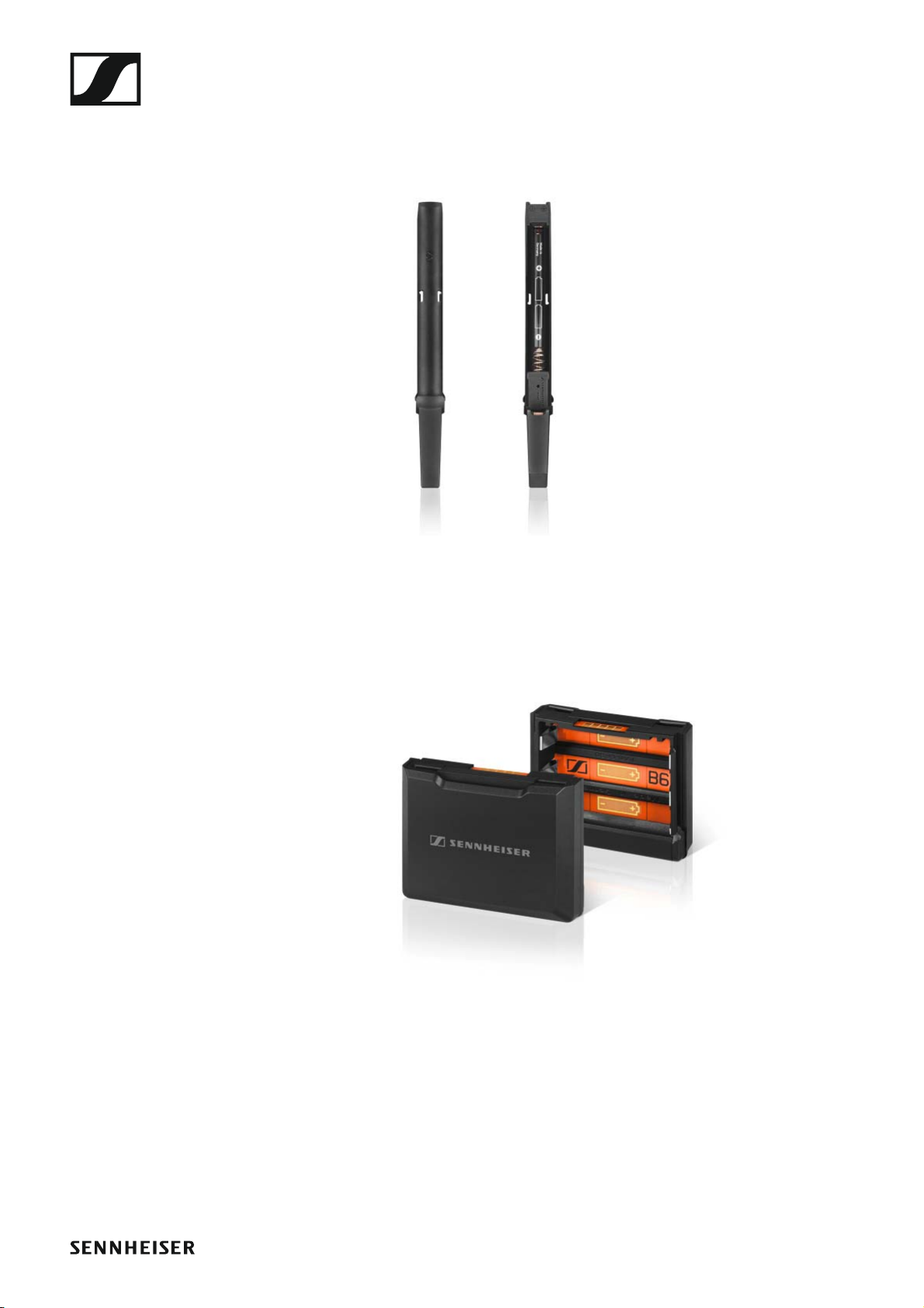
B 61 battery compartment
The B 61 battery compartment is intended to operate the SK 6000
bodypack transmitter.
►
Sennheiser article number 504701
26
Page 28
Accessories
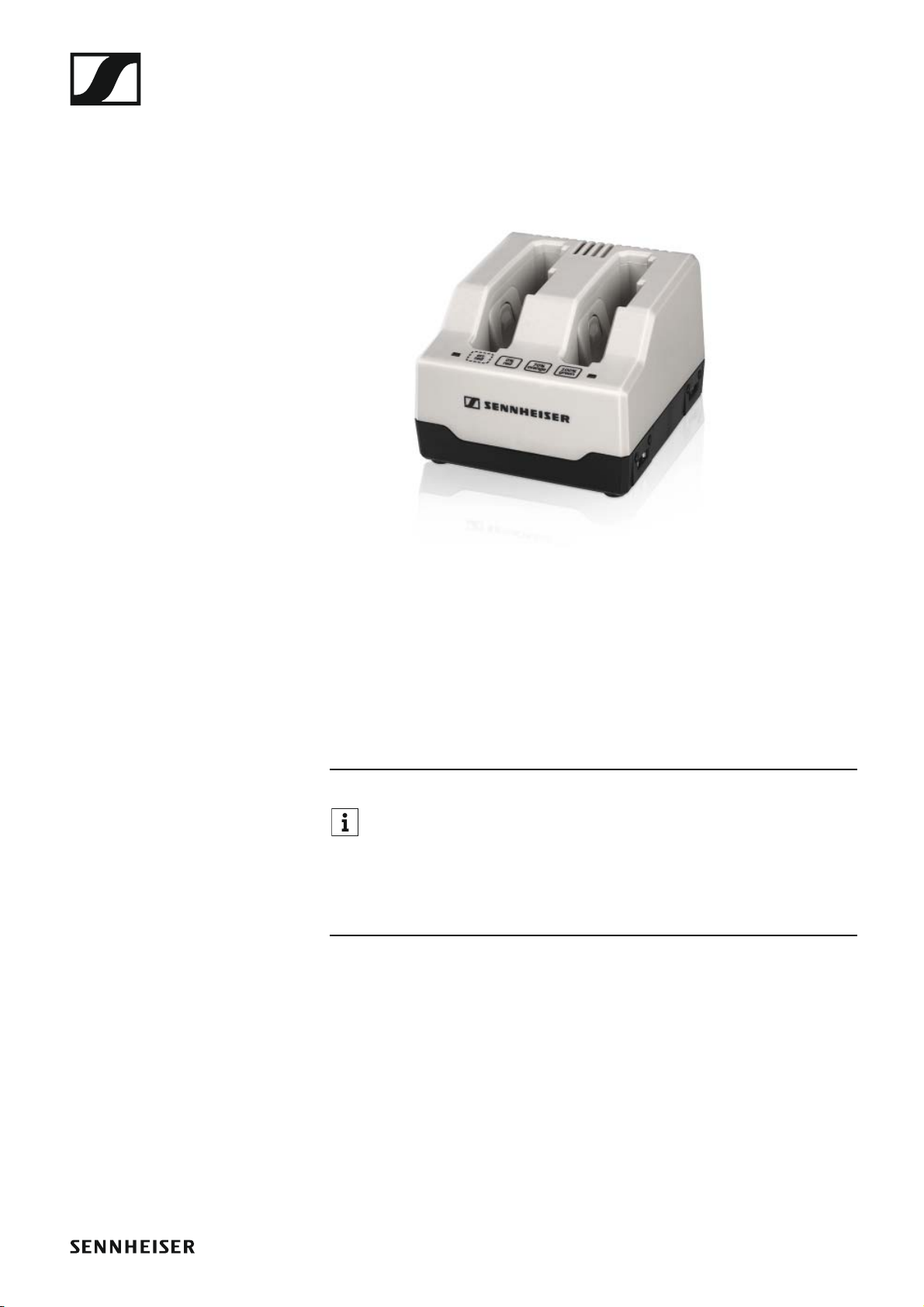
L60 charger
As an alternative to the L 6000 charger, the L 60 charger from the
Digital 9000 series can be used to charge the BA 60 and BA 61 rechargeable batteries.
►
Features:
• Simultaneous charging of up to 2 rechargeable batteries of type BA 60/
BA 61
• Cascade up to 4 chargers
Sennheiser article no. 504704
You can find more information about the L 60 charger in the
Digital 9000 series instruction manual in the Sennheiser Documentation app, or on the L 60 charger product page at the following ad-
dress:
www.sennheiser.com/l-60
27
Page 29
Accessories
Digital 9000 series handheld transmitter and bodypack transmitter
The Sennheiser Digital 9000 series SK 9000 bodypack transmitter and
SKM 9000 handheld transmitter are compatible with the Digital 6000 se-
ries if operated in LR mode.
The SKM 9000 COM variant of the handheld transmitter has a Command
button for use in command mode (see „Command Mode menu item“).
SKM 9000 product variants
►
Product Frequency range Article
no.
SKM 9000 A1-A4, black 470 to 558 MHz 504718
SKM 9000 A5-A8, black 550 to 638 MHz 504719
SKM 9000 B1-B4, black 630 to 718 MHz 504720
SKM 9000 COM A1-A4, black 470 to 558 MHz 504714
SKM 9000 COM A5-A8, black 550 to 638 MHz 504715
SKM 9000 COM B1-B4, black 630 to 718 MHz 504716
SKM 9000 A1-A4, nickel 470 to 558 MHz 504726
SKM 9000 A5-A8, nickel 550 to 638 MHz 504727
SKM 9000 B1-B4, nickel 630 to 718 MHz 504728
SKM 9000 COM A1-A4, nickel 470 to 558 MHz 504722
SKM 9000 COM A5-A8, nickel 550 to 638 MHz 504723
SKM 9000 COM B1-B4, nickel 630 to 718 MHz 504724
SK 9000 product variants
►
Product Frequency range Article
no.
SK 9000 A1-A4 470 to 558 MHz 504730
SK 9000 A5-A8 550 to 638 MHz 504731
SK 9000 B1-B4 630 to 718 MHz 504732
28
Page 30
Accessories
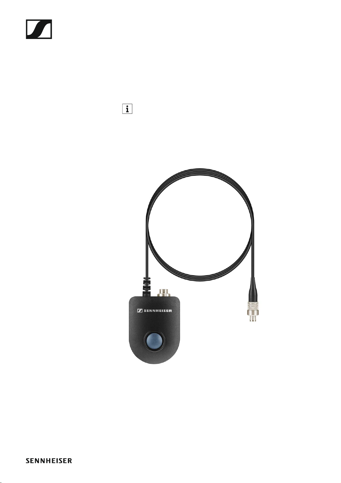
KA 9000 COM command adapter
Command adapter for the SK 6000 bodypack transmitter. You can use the
KA 9000 COM command adapter to switch the audio channel on the EM
6000 receiver via remote control (for example, to provide directional instructions).
Article no. 504735
You can find more detailed information about the KA 9000 COM command adapter in the following sections:
• Installation: „Connecting the KA 9000 COM command adapter to the SK
6000“
• Operation: „Operating the SK 6000 with the KA 9000 COM command
adapter“
►
29
Page 31

Accessories
Microphones and cables
Microphone modules
We recommend using the following microphone modules with the
SKM 6000 handheld transmitter.
►
Module Features Article no.
MMD 835-1 BK Dynamic, cardioid, black 502575
MMD 845-1 BK Dynamic, super-cardioid, black 502576
MME 865-1 BK Capacitor, super-cardioid, black 502581
MMD 935-1 BK Dynamic, cardioid, black 502577
MMD 945-1 BK Dynamic, super-cardioid, black 502579
MMK 965-1 BK Capacitor, switchable, black 502582
MMK 965-1 NI Capacitor, switchable, nickel 502584
MD 9235 BK Dynamic, super-cardioid, black 502585
MD 9235 NI Dynamic, super-cardioid, nickel 502586
MD 9235 NI/BK Dynamic, super-cardioid, nickel-black 502591
ME 9002 Electret, omni-directional, black 502587
ME 9004 Electret, cardioid, black 502588
ME 9005 Electret, super-cardioid, black 502589
Neumann
Capacitor, cardioid, nickel 008651
KK 204
Neumann
Capacitor, cardioid, black 008652
KK 204 BK
Neumann
Capacitor, super-cardioid, nickel 008653
KK 205
Neumann
Capacitor, super-cardioid, black 008654
KK 205 BK
You can also use microphone modules from the G3/G4 evolution
wireless and 2000 series with the SKM 6000 handheld transmitter.
You can find more information about the individual microphone modules on
their respective product pages at www.sennheiser.com or www.neumann.com.
30
Page 32

Accessories
Headset and Lavalier microphones
We recommend using the following Lavalier microphones and headset microphones with the SK 6000 and SK 6212 bodypack transmitters.
►
Microphone Features Article no.
MKE 1-4 Lavalier microphone, omni-directional 502167
MKE 2-4 Lavalier microphone, omni-directional 004736
MKE 40-4 Lavalier microphone, cardioid 003579
HSP 2 Headset microphone, omni-directional 009862
HSP 4 Headset microphone, cardioid 009864
SL Headmic 1-4 Headset microphone, omni-directional 506905
HSP Essential
Omni Black
Headset microphone, omni-directional,
black
508247
3-pin
HSP Essential
Omni Beige
Headset microphone, omni-directional,
beige
508248
3-pin
MKE Essential
Omni Black
Lavalier microphone, omni-directional,
black
508251
3-pin
MKE Essential
Omni Beige
Lavalier microphone, omni-directional,
beige
508252
3-pin
You can find more information about the individual microphones on
their respective product pages at www.sennheiser.com.
Line/instrument cables
The following cable is available to connect instruments and line sources to
the SK 6000 bodypack transmitter:
•Sennheiser CI 1-4
6.3 mm (1/4") jack plug (silent plug) to 3-pin audio connector (Sennheiser special connector), article no. 503163
The following cable is available to connect instruments and line sources to
the SK 6212 bodypack transmitter:
•Sennheiser CI R-4A-NRS
6.3 mm (1/4") jack plug (silent plug) to 3-pin audio connector (Sennheiser special connector), article no. 390027
AES3 cable for digital audio signals
To connect the digital audio output of the EM 6000 to a digital mixing console.
• GZL AES 10, AES3 cable, 10 m (32 ft), 110 Ω, double-shielded, article no.
502432
31
Page 33

Accessories
Antennas and accessories
The following antenna components are available as accessory parts.
Omni-directional antennas
• A 1031-U, passive omni-directional antenna, article no. 004645
• A 3700, active omni-directional antenna, article no. 502195
Directional antennas
• A 2003 UHF, passive directional antenna, article no. 003658
• AD 3700, active directional antenna, article no. 502197
Circularly polarized antennas
• A 5000 CP, passive circularly polarized helical antenna, article no.
500887
Antenna splitter
• ASA 3000, active antenna splitter 2×1:8
• ASA 3000-EU variant, article no. 009423
• ASA 3000-UK variant, article no. 009408
• ASA 3000-US variant, article no. 009407
Antenna amplifiers
• AB 3700, broadband antenna amplifier, article no. 502196
• AB 9000, antenna amplifier
• AB 9000 A1-A8 variant, article no. 504708
• AB 9000 B1-B8 variant, article no. 504709
Antenna cables
• GZL 1019, BNC/BNC coaxial cable, antenna cable with 50 Ω characteristic (wave) impedance
• GZL 1019-A1 variant, 1 m (3 ft), article no. 002324
• GZL 1019-A5 variant, 5 m (16 ft), article no. 002325
• GZL 1019-A10 variant, 10 m (32 ft), article no. 002326
• RF cable, BNC cable for daisy chaining the antenna signal, 50 Ω, 0.25 m
(9 27/32"), article no. 087969
• RF cable, BNC cable for daisy chaining the word clock signal, 75 Ω,
0.25 m (9 27/32"), article no. 087972
Antennas for bodypack transmitters
• Antenna A1-A4, antenna for SK 6212, article no. 508572
• Antenna A4-A8, antenna for SK 6212, article no. 508573
• Antenna B1-B4, antenna for SK 6212, article no. 508574
32
Page 34

Installing Digital 6000 series devices
INSTALLATION
Installing Digital 6000 series devices
You can find information about installing and connecting Digital 6000 series devices in the following sections.
• EM 6000 2-channel receiver >> „Installing the EM 6000“
• SKM 6000 handheld transmitter >> „Installing the SKM 6000“
• SK 6000 bodypack transmitter >> „Installing the SK 6000“
• SK 6212 bodypack transmitter >> „Installing the SK 6212“
33
Page 35

Installing Digital 6000 series devices
• L 6000 charger and LM 6060, LM 6061, LM 6062 charging modules >>
„Installing the L 6000 | LM 6060 | LM 6061 | LM 6062“
You can find information about operating the products under „Using
Digital 6000 series devices“.
34
Page 36

Installing the EM 6000
Installing the EM 6000
These sections contain detailed information about installing the EM 6000.
You can find information about operating the EM 6000 under „Using the
EM 6000“.
Connectors on the rear of the device
Product overview for the rear side of the EM 6000
►
1 Power socket
• See „Connecting/disconnecting the EM 6000 to/from the power
supply system“
2 Ethernet socket for controlling the device via the network and Sennhe-
iser WSM
• See „Connecting the EM 6000 to a network“
3 Digital Audio AES 3 digital audio output
• See „Outputting digital audio signals“
4 Word clock BNC sockets
• See „Connecting the word clock“
5 Bal AF out analog audio outputs for the CH 1 and CH 2 channels
• One XLR and 6.3 mm (1/4") jack per channel, transformer-balanced,
parallel
• See „Outputting analog audio signals“
6 BNC antenna inputs and BNC antenna outputs for cascading
• See „Connecting remote antennas“
• See „Connecting rod antennas“
• See „Recommendations for using antennas“
35
Page 37

Installing the EM 6000
Product overview for the rear side of the EM 6000 DANTE
►
1 Power socket
• See „Connecting/disconnecting the EM 6000 to/from the power
supply system“
2 Dante™ interface with two RJ-45 sockets, Primary and Secondary
• See „Outputting audio via a Dante™ network (EM 6000 DANTE only)“
3 Ethernet socket for controlling the device via the network and Sennhe-
iser WSM
• See „Connecting the EM 6000 to a network“
4 Digital Audio AES 3 digital audio output
• See „Outputting digital audio signals“
5 Word clock BNC sockets
• See „Connecting the word clock“
6 Bal AF out analog audio outputs for the CH 1 and CH 2 channels
• One XLR and 6.3 mm (1/4") jack per channel, transformer-balanced,
parallel
• See „Outputting analog audio signals“
7 BNC antenna inputs and BNC antenna outputs for cascading
• See „Connecting remote antennas“
• See „Connecting rod antennas“
• See „Recommendations for using antennas“
36
Page 38

Installing the EM 6000
Connecting/disconnecting the EM 6000 to/from the power supply system
To connect the EM 6000 to the power supply system:
▷ Connect the mains cable IEC connector to the power socket on the rear
side of the EM 6000.
▷ Connect the mains cable plug into a suitable wall socket.
►
Once the EM 6000 is connected to the power supply, the On/Off button lights up dimmed. If the booster voltage for antennas is activated
in the menu (see „System -> Booster Feed menu item“), it is active al-
ready before you switch on and after you switch off the EM 6000.
To completely disconnect the EM 6000 from the power supply system:
▷ Unplug the mains cable plug from the wall socket.
▷ Unplug the mains cable IEC connector from the power socket on the
rear side of the EM 6000.
37
Page 39

Installing the EM 6000
Connecting the EM 6000 to a network
You can monitor and control one or more EM 6000s via a network connection using Sennheiser Wireless Systems Manager (WSM) software.
The network does not have to be a homogeneous network including
only receivers. You can integrate the EM 6000 into your existing network infrastructure with any other types of devices.
►
To connect the EM 6000 to a network:
▷ Connect a network cable with an RJ-45 connector (Cat5 at minimum)
to the Ethernet socket on the rear side of the EM 6000.
►
For more information about controlling devices via the Sennheiser
Wireless Systems Manager (WSM) software, refer to the instruction
manual for the software. You can download the software here:
www.sennheiser.com/wsm
38
Page 40

Installing the EM 6000
Outputting analog audio signals
Each of the two channels CH 1 and CH 2 on the EM 6000 have both a symmetrical XLR-3M output socket and a symmetrical 6.3 mm (1/4") jack output socket.
▷ Always use only one of the two Bal AF out output sockets for each
channel.
The two output sockets of a channel are connected in parallel.
To connect an XLR cable:
►
To connect a jack cable:
►
39
Page 41

Installing the EM 6000
Outputting digital audio signals
The EM 6000 can also output digital audio.
To do so, use the Digital Audio AES 3 output on the rear side of the
EM 6000.
The Digital Audio AES 3 output socket is designed as an XLR-3M
socket. Use an XLR cable with a resistance of 110 ohm. Conventional
XLR audio cables may not transfer the digital audio signal correctly.
►
40
Page 42

Installing the EM 6000
Outputting audio via a Dante™ network (EM 6000 DANTE only)
The EM 6000 DANTE has a Dante interface (Audinate Brooklyn II) for outputting digital audio signals via a Dante™ network.
▷ Connect a Dante-enabled network cable to the Dante socket on the
rear side of the EM 6000 DANTE.
►
We recommend using an Ethernet connector as shown in the figure.
You can find more information about Dante™ here:
• „Word clock scenarios for digital audio (AES3 and Dante™)“
• „System -> Dante Settings (only EM 6000 DANTE) menu item“
41
Page 43

Installing the EM 6000
Connecting the word clock
You can use the internal word clock on the EM 6000 or connect an external
word clock.
You can also output the external word clock and cascade it up to 16 receivers.
The word clock output transmits only the external word clock that is connected via the word clock input. The internal word clock is not output via
the word clock output.
For more information about the word clock, see „Word clock scenarios for digital audio (AES3 and Dante™)“.
To connect an external word clock:
►
▷ Use a coaxial BNC cable (75 Ω) to connect the external word clock to
the Wordclock In input.
A suitable cable is available as an accessory part. See „Antenna cables“.
42
Page 44

Installing the EM 6000
To cascade the word clock:
▷ Connect the Wordclock In input of the next EM 6000 to the Wordclock
Out output of the previous EM 6000.
►
43
Page 45

Installing the EM 6000
Connecting remote antennas
We recommend using remote antennas. You can also find useful information about using antennas under „Recommendations for using antennas“.
To connect remote antennas:
▷ Connect the first antenna to the RF in socket for Antenna A on the rear
side of the EM 6000.
▷ Connect the second antenna to the RF in socket for Antenna B on the
rear side of the EM 6000.
►
Note the following information when setting up antennas:
▷ Maintain a distance of at least 1 m (3 ft) between the antennas.
▷ Maintain a distance of at least 0.5 m (1.5 ft) between the antennas and
the nearest wall.
▷ Position the antennas so that there is a direct line of sight between the
transmitters and the antennas.
▷ Refer to the more detailed information under „Remote antennas“.
▷ Activate the booster feed in the EM 6000 menu if you are using active
antennas. See „System -> Booster Feed menu item“ in the chapter
„System menu item“. Alternatively, use an external antenna amplifier.
44
Page 46

Installing the EM 6000
Cascading receivers
For larger 4-channel systems, you can cascade up to 8 receivers without
using additional antenna splitters and you then require only one pair of antennas.
►
45
Page 47

Installing the EM 6000
Connecting rod antennas
We recommend using remote antennas. You can also find useful information about using antennas under „Recommendations for using antennas“.
To connect the supplied rod antennas:
▷ Connect the first rod antenna to the RF in socket for Antenna A on the
rear side of the EM 6000.
▷ Connect the second rod antenna to the RF in socket for Antenna B on
the rear side of the EM 6000.
▷ Gently angle the rod antennas to the left and right as shown in the fig-
ure.
►
46
Page 48

Installing the EM 6000
Installing the EM 6000 in a rack
You can install the EM 6000 2-channel receiver in any conventional 19"
rack. The rack mounting angles are already attached to the device.
Always observe the following information during rack mounting.
▷ Support the EM 6000 after installation in the rack.
Due to the weight and depth of the device, there is a risk that it may
break off in the rack and become damaged as a result.
►
Version A:
▷ Use special rack mounting rails.
▷ The design of the rack used must be suitable for the installation of
these mounting rails.
Version B:
▷ Use a suitable object to support the device on the rear side.
▷ Ensure that this object cannot become loose.
ATTENTION
Material damages caused by devices overheating
When there is insufficient ventilation, the devices mounted in the rack may
overheat.
▷ Ensure that there is sufficient ventilation in the rack, particularly if sev-
eral devices are installed. If necessary, install a fan in the rack.
►
47
Page 49

Installing the SKM 6000
Installing the SKM 6000
These sections contain detailed information about installing the
SKM 6000.
You can find information about operating the SKM 6000 under „Using the
SKM 6000“.
48
Page 50

Installing the SKM 6000
Inserting and removing the BA 60 rechargeable battery
We recommend using the BA 60 rechargeable battery instead of the
B 60 battery compartment. You can find more information about this
subject under „Rechargeable batteries and battery compartments“.
▷ Charge the BA 60 rechargeable battery before using it for the first time.
For information about charging, see „Charging rechargeable batteries“.
►
To insert the BA 60 rechargeable battery into the SKM 6000 handheld
transmitter:
▷ Insert the BA 60 rechargeable battery into the SKM 6000 handheld
transmitter as shown in the figure until it audibly clicks into place.
►
49
Page 51

Installing the SKM 6000
To remove the BA 60 rechargeable battery from the SKM 6000 handheld
transmitter:
▷ Press the two catches as shown in the figure and pull the BA 60 re-
chargeable battery out of the SKM 6000 handheld transmitter.
►
CAUTION
Damage to the handheld transmitter and/or rechargeable battery/battery compartment
If you touch the following contacts, they may become dirty or bent.
• BA 60 rechargeable battery charging and data contacts
• B 60 battery compartment contacts
▷ Do not touch the BA 60 rechargeable battery contacts or the B 60 bat-
tery compartment contacts.
►
50
Page 52

Installing the SKM 6000
Inserting and removing the B 60 battery compartment
We recommend using the BA 60 rechargeable battery instead of the
B 60 battery compartment. You can find more information about this
subject under „Rechargeable batteries and battery compartments“.
Before using the battery compartment, you must insert the batteries as
shown in the figure.
▷ Please observe correct polarity when inserting the batteries.
▷ Use only high-quality AA batteries (e.g. lithium or alkaline manganese
batteries) or high-quality NiMH rechargeable batteries in the B 60 battery compartment.
►
To insert the B 60 battery compartment into the SKM 6000 handheld
transmitter:
▷ Insert the B 60 battery compartment into the SKM 6000 handheld
transmitter as shown in the figure until it audibly clicks into place.
►
51
Page 53

Installing the SKM 6000
To remove the B 60 battery compartment from the SKM 6000 handheld
transmitter:
▷ Press the two catches as shown in the figure and pull the B 60 battery
compartment out of the SKM 6000 handheld transmitter.
►
CAUTION
Damage to the handheld transmitter and/or rechargeable battery/battery compartment
If you touch the following contacts, they may become dirty or bent.
• BA 60 rechargeable battery charging and data contacts
• B 60 battery compartment contacts
▷ Do not touch the BA 60 rechargeable battery contacts or the B 60 bat-
tery compartment contacts.
►
52
Page 54

Installing the SKM 6000
Replacing the microphone module
We recommend using the following microphone modules with the
SKM 6000 handheld transmitter.
►
Module Features Article no.
MMD 835-1 BK Dynamic, cardioid, black 502575
MMD 845-1 BK Dynamic, super-cardioid, black 502576
MME 865-1 BK Capacitor, super-cardioid, black 502581
MMD 935-1 BK Dynamic, cardioid, black 502577
MMD 945-1 BK Dynamic, super-cardioid, black 502579
MMK 965-1 BK Capacitor, switchable, black 502582
MMK 965-1 NI Capacitor, switchable, nickel 502584
MD 9235 BK Dynamic, super-cardioid, black 502585
MD 9235 NI Dynamic, super-cardioid, nickel 502586
MD 9235 NI/BK Dynamic, super-cardioid, nickel-black 502591
ME 9002 Electret, omni-directional, black 502587
ME 9004 Electret, cardioid, black 502588
ME 9005 Electret, super-cardioid, black 502589
Neumann
Capacitor, cardioid, nickel 008651
KK 204
Neumann
Capacitor, cardioid, black 008652
KK 204 BK
Neumann
Capacitor, super-cardioid, nickel 008653
KK 205
Neumann
Capacitor, super-cardioid, black 008654
KK 205 BK
You can also use microphone modules from the evolution wireless
G3 and 2000 series with the SKM 6000 handheld transmitter.
53
Page 55

Installing the SKM 6000
To change the microphone module:
▷ Screw or unscrew the microphone module onto or from the handheld
transmitter as shown in the figure.
►
With some microphone modules, the upper part of the microphone
basket can be screwed off. Ensure that you always completely unscrew the microphone module.
CAUTION
Damage to the microphone module
If you touch the contacts, they may become dirty or bent.
▷ Do not touch the handheld transmitter contacts or the microphone
module contacts.
►
54
Page 56

Installing the SK 6000
Installing the SK 6000
These sections contain detailed information about installing the SK 6000.
You can find information about operating the SK 6000 under „Using the
SK 6000“.
55
Page 57

Installing the SK 6000
Inserting and removing the BA 61 rechargeable battery
We recommend using the BA 61 rechargeable battery instead of the
B 61 battery compartment. You can find more information about this
subject under „Rechargeable batteries and battery compartments“.
▷ Charge the BA 61 rechargeable battery before using it for the first time.
For information about charging, see „Charging rechargeable batteries“.
►
To insert the BA 61 rechargeable battery into the SK 6000 bodypack transmitter:
▷ Insert the BA 61 rechargeable battery into the SK 6000 bodypack trans-
mitter as shown in the figure until it audibly clicks into place.
►
56
Page 58

Installing the SK 6000
To remove the BA 61 rechargeable battery from the SK 6000 bodypack
transmitter:
▷ Press the two catches as shown in the figure and pull the BA 61 re-
chargeable battery out of the SK 6000 bodypack transmitter.
►
CAUTION
Damage to the bodypack transmitter and/or rechargeable battery/
battery compartment
If you touch the following contacts, they may become dirty or bent.
• Supply voltage contacts and bodypack transmitter contacts
• BA 61 rechargeable battery charging and data contacts
• B 61 battery compartment contacts
▷ Do not touch the BA 61 rechargeable battery contacts or the B 61 bat-
tery compartment contacts.
►
57
Page 59

Installing the SK 6000
Inserting and removing the B 61 battery compartment
We recommend using the BA 61 rechargeable battery instead of the
B 61 battery compartment. You can find more information about this
subject under „Rechargeable batteries and battery compartments“.
Before using the battery compartment, you must insert the batteries as
shown in the figure.
▷ Please observe correct polarity when inserting the batteries.
▷ Use only high-quality AA batteries (e.g. lithium or alkaline manganese
batteries) or high-quality NiMH rechargeable batteries in the B 61 battery compartment.
►
To insert the B 61 battery compartment into the SK 6000 bodypack transmitter:
▷ Insert the B 61 battery compartment into the SK 6000 bodypack trans-
mitter as shown in the figure until it audibly clicks into place.
►
58
Page 60

Installing the SK 6000
To remove the B 61 battery compartment from the SK 6000 bodypack
transmitter:
▷ Press the two catches as shown in the figure and pull the B 61 battery
compartment out of the SK 6000 bodypack transmitter.
►
CAUTION
Damage to the bodypack transmitter and/or rechargeable battery/
battery compartment
If you touch the following contacts, they may become dirty or bent.
• Supply voltage contacts and bodypack transmitter contacts
• BA 61 rechargeable battery charging and data contacts
• B 61 battery compartment contacts
▷ Do not touch the BA 61 rechargeable battery contacts or the B 61 bat-
tery compartment contacts.
►
59
Page 61

Installing the SK 6000
Mounting the antenna
To mount the supplied antenna:
▷ Connect the antenna to the SK 6000 bodypack transmitter antenna
socket as shown in the figure.
▷ Tightly screw on the antenna coupling ring on the SK 6000 bodypack
transmitter antenna socket.
►
The antenna can be connected to the antenna socket very gently in
only one direction. Do not use force to connect the antenna to the
bodypack transmitter antenna socket.
60
Page 62

Installing the SK 6000
Connecting a microphone to the SK 6000
We recommend using the following Lavalier microphones and headset microphones with the SK 6000 and SK 6212 bodypack transmitters.
►
Microphone Features Article no.
MKE 1-4 Lavalier microphone, omni-directional 502167
MKE 2-4 Lavalier microphone, omni-directional 004736
MKE 40-4 Lavalier microphone, cardioid 003579
HSP 2 Headset microphone, omni-directional 009862
HSP 4 Headset microphone, cardioid 009864
SL Headmic 1-4 Headset microphone, omni-directional 506905
HSP Essential
Omni Black
Headset microphone, omni-directional,
black
508247
3-pin
HSP Essential
Omni Beige
Headset microphone, omni-directional,
beige
508248
3-pin
MKE Essential
Omni Black
Lavalier microphone, omni-directional,
black
508251
3-pin
MKE Essential
Omni Beige
Lavalier microphone, omni-directional,
beige
508252
3-pin
To connect a microphone to the bodypack transmitter:
▷ Use a 3-pin audio connector to connect the microphone cable to the
SK 6000 bodypack transmitter audio socket as shown in the figure.
▷ Tightly screw on the microphone cable coupling ring on the audio sock-
et thread of the SK 6000 bodypack transmitter.
►
For more information about using the particular microphone, see the
corresponding instruction manual for the microphone. You can find
this instruction manual in the download section of the Sennheiser
website under www.sennheiser.com/download.
61
Page 63

Installing the SK 6000
Connecting an instrument or line source to the SK 6000
You can connect instruments or audio sources with a line level to the
SK 6000 bodypack transmitter.
To do so, you require the Sennheiser CI 1-4 cable (6.3 mm (1/4") jack plug
to 3-pin audio connector)
To connect an instrument or line source to bodypack transmitter:
▷ Connect the 3-pin audio connector of the CI 1-4 cable to the SK 6000
bodypack transmitter audio socket as shown in the figure.
▷ Tightly screw on the audio cable coupling ring on the audio socket
thread of the SK 6000 bodypack transmitter.
►
62
Page 64

Installing the SK 6000
Connecting the KA 9000 COM command adapter to the SK 6000
You can use the KA 9000 COM command adapter to switch the audio channel on the EM 6000 receiver via remote control (for example, to provide directional instructions).
To connect the KA 9000 COM command adapter to the bodypack transmitter:
▷ Connect the 3-pin audio connector of the KA 9000 COM to the SK 6000
bodypack transmitter audio socket as shown in the figure.
▷ Connect the 3-pin audio connector of the Sennheiser microphone or
Sennheiser CI 1-4 line/instrument cable to the KA 9000 COM audio
socket.
►
63
Page 65

Installing the SK 6212
Installing the SK 6212
These sections contain detailed information about installing the SK 6212.
You can find information about operating the SK 6212 under „Using the
SK 6212“.
Inserting and removing the BA 62 rechargeable battery
▷ Charge the BA 62 rechargeable battery before using it for the first time.
For information about charging, see „Charging rechargeable batteries“.
To insert the BA 62 rechargeable battery into the SK 6212 bodypack transmitter:
▷ Open the battery compartment on the SK 6212 bodypack transmitter as
shown in the figure.
▷ Insert the BA 62 rechargeable battery into the SK 6212 bodypack trans-
mitter as shown in the figure.
▷ Close the battery compartment cover until it clicks into place.
►
64
Page 66

Installing the SK 6212
To remove the BA 62 rechargeable battery from the SK 6212 bodypack
transmitter:
▷ Open the battery compartment on the SK 6212 bodypack transmitter as
shown in the figure.
▷ Remove the BA 62 rechargeable battery from the SK 6212 bodypack
transmitter.
CAUTION
Damage to the bodypack transmitter and/or rechargeable battery/
battery compartment
If you touch the following contacts, they may become dirty or bent.
• Supply voltage contacts and bodypack transmitter contacts
• BA 62 rechargeable battery charging and data contacts
▷ Do not touch the contacts on the BA 62 rechargeable battery or the
SK 6212 bodypack transmitter.
►
65
Page 67

Installing the SK 6212
Mounting the antenna
To mount the supplied antenna:
▷ Connect the antenna to the SK 6212 bodypack transmitter antenna
socket as shown in the figure.
▷ Tightly screw the antenna coupling ring onto the SK 6212 bodypack
transmitter antenna socket.
►
The antenna can be connected to the antenna socket very gently in
only one direction. Do not use force to connect the antenna to the
bodypack transmitter antenna socket.
66
Page 68

Installing the SK 6212
The antenna bends very easily.
▷ Make sure that the antenna does not touch the housing of the bodypack
transmitter.
►
67
Page 69

Installing the SK 6212
Connecting a microphone to the SK 6212
We recommend using the following Lavalier microphones and headset microphones with the SK 6000 and SK 6212 bodypack transmitters.
►
Microphone Features Article no.
MKE 1-4 Lavalier microphone, omni-directional 502167
MKE 2-4 Lavalier microphone, omni-directional 004736
MKE 40-4 Lavalier microphone, cardioid 003579
HSP 2 Headset microphone, omni-directional 009862
HSP 4 Headset microphone, cardioid 009864
SL Headmic 1-4 Headset microphone, omni-directional 506905
HSP Essential
Omni Black
3-pin
HSP Essential
Omni Beige
3-pin
MKE Essential
Omni Black
3-pin
MKE Essential
Omni Beige
3-pin
Headset microphone, omni-directional,
black
Headset microphone, omni-directional,
beige
Lavalier microphone, omni-directional,
black
Lavalier microphone, omni-directional,
beige
508247
508248
508251
508252
68
Page 70

Installing the SK 6212
To connect a microphone to the bodypack transmitter:
▷ Use a 3-pin audio connector to connect the microphone cable to the
SK 6212 bodypack transmitter audio socket as shown in the figure.
▷ Tightly screw the microphone cable coupling ring onto the audio socket
thread of the SK 6212 bodypack transmitter.
►
For more information about using the particular microphone, see the
corresponding instruction manual for the microphone. You can find
this instruction manual in the download section of the Sennheiser
website under www.sennheiser.com/download.
69
Page 71

Installing the SK 6212
Connecting an instrument or line source to the SK 6212
You can connect instruments or audio sources with a line level to the
SK 6212 bodypack transmitter.
To do so, you require the Sennheiser CI R-4A-NRS cable (6.3 mm (1/4")
jack plug to 3-pin audio connector)
To connect an instrument or line source to bodypack transmitter:
▷ Connect the 3-pin audio connector of the CI R-4A-NRS cable to the
SK 6212 bodypack transmitter audio socket as shown in the figure.
▷ Tightly screw on the audio cable coupling ring on the audio socket
thread of the SK 6212 bodypack transmitter.
►
70
Page 72

Installing the L 6000 | LM 6060 | LM 6061 | LM 6062
Installing the L 6000 | LM 6060 |
LM 6061 | LM 6062
These sections contain detailed information about installing the L 6000.
You can find information about operating the L 6000 under „Using the
L6000“.
Connecting/disconnecting the L 6000 to/from the power supply system
To connect the L 6000 to the power supply system:
▷ Connect the mains cable IEC connector to the power socket on the rear
side of the L 6000.
▷ Connect the mains cable plug into a suitable wall socket.
►
To completely disconnect the L 6000 from the power supply system:
▷ Unplug the mains cable plug from the wall socket.
▷ Unplug the mains cable IEC connector from the power socket on the
rear side of the L 6000.
71
Page 73

Installing the L 6000 | LM 6060 | LM 6061 | LM 6062
Connecting the L 6000 to a network
You can monitor and control one or more L 6000s via a network connection
using Sennheiser Wireless Systems Manager (WSM) software.
The network does not have to be a homogeneous network including only
chargers. You can integrate the L 6000 into your existing network infrastructure with any other types of devices.
►
To connect the L 6000 to a network:
▷ Connect a network cable with an RJ-45 connector (Cat5 at minimum)
to the Ethernet socket on the rear side of the L 6000.
►
For more information about controlling devices via the Sennheiser
Wireless Systems Manager (WSM) software, refer to the instruction
manual for the software. You can download the software here:
www.sennheiser.com/wsm
72
Page 74

Installing the L 6000 | LM 6060 | LM 6061 | LM 6062
Installing the LM 6060, LM 6061 and LM 6062 charging modules in the L 6000
The following charging modules are available for the L 6000 charger:
• LM 6060 -> for charging the BA 60 rechargeable battery
►
• LM 6061 -> for charging the BA 61 rechargeable battery
►
• LM 6062 -> for charging the BA 62 rechargeable battery
►
You can combine the LM 6060, LM 6061 and LM 6062 in any way in the
L 6000 charger.
73
Page 75

Installing the L 6000 | LM 6060 | LM 6061 | LM 6062
To install a charging module in the L 6000 charger:
▷ Completely disconnect the L 6000 charger from the power supply sys-
tem. See „Connecting/disconnecting the L 6000 to/from the power
supply system“.
▷ Unscrew one of the dummy caps on the L 6000.
To do so, you require a Torx 10 screwdriver.
►
▷ Fully slide the charging module into the open charging slot as shown in
the figure.
The charging module can be inserted into the L 6000 housing only in
one direction. The Sennheiser lettering on the charging module must
face upward.
►
▷ Tightly screw on the charging module.
Always use the latest firmware for the L 6000 charger (version 2.0 or later)
to ensure you have access to the full range of functions. You can download
the latest firmware from the following address:
http://www.sennheiser.com/l-6000
For more detailed information about charging the BA 60, BA 61 and
BA 62 rechargeable batteries, see „Charging rechargeable batteries“.
74
Page 76

Installing the L 6000 | LM 6060 | LM 6061 | LM 6062
Installing the L 6000 in a rack
You can install the L 6000 charger in any conventional 19" rack. The rack
mounting angles are already attached to the device.
Always observe the following information during rack mounting.
▷ Support the L 6000 charger after installation in the rack.
Due to the weight and depth of the device, there is a risk that it may
break off in the rack and become damaged as a result.
►
Version A:
▷ Use special rack mounting rails.
▷ The design of the rack used must be suitable for the installation of
these mounting rails.
Version B:
▷ Use a suitable object to support the device on the rear side.
▷ Ensure that this object cannot become loose.
ATTENTION
Material damages caused by devices overheating
When there is insufficient ventilation, the devices mounted in the rack may
overheat.
▷ Ensure that there is sufficient ventilation in the rack, particularly if sev-
eral devices are installed. If necessary, install a fan in the rack.
►
75
Page 77

Using Digital 6000 series devices
OPERATION
Using Digital 6000 series devices
You can find information about using Digital 6000 series devices in the
following sections.
• EM 6000 2-channel receiver >> „Using the EM 6000“
• SKM 6000 handheld transmitter >> „Using the SKM 6000“
• SK 6000 bodypack transmitter >> „Using the SK 6000“
• SK 6212 bodypack transmitter >> „Using the SK 6212“
76
Page 78

Using Digital 6000 series devices
• L 6000 charger and LM 6060, LM 6061, LM 6062 charging modules >>
„Using the L 6000“
You can find information about installing the products under „Installing Digital 6000 series devices“.
In the sections below, you can find important information about specific
use cases.
• Establishing a radio link between the transmitter and receiver >> „Establishing a radio link“
• Synchronizing the receiver settings to the transmitter >> „Synchronizing devices“
•Using the operating menu of the receiver >> „Displays on the EM 6000
display panel“
• Information about status messages and error messages on the display >> „Status messages“
77
Page 79

Using the EM 6000
Using the EM 6000
These sections contain detailed information about operating the EM 6000.
You can find information about installing the EM 6000 under „Installing the
EM 6000“.
Operating elements on the front of the device
Product overview for the front of the EM 6000
►
1 Displaying and using channel 1 (CH 1)
• See „Displays on the EM 6000 display panel“
• See „Buttons for navigating through the menu“
2 Displaying and using channel 2 (CH 2)
• See „Displays on the EM 6000 display panel“
• See „Buttons for navigating through the menu“
3 On/Off button
• See „Switching the EM 6000 on and off“
4 SAVE button for saving settings in the menu (separate for CH 1 and CH
2)
• See „Buttons for navigating through the menu“
5 ESC button for canceling an action in the menu (separate for CH 1 and
CH 2)
• See „Buttons for navigating through the menu“
78
Page 80

Using the EM 6000
6 Headphone button for listening in the particular channel via the HEAD-
PHONES socket (13) (separate for CH 1 and CH 2)
• See „Using the headphone output“
7 SYNC button for synchronizing the channel settings to a transmitter
(separate for CH 1 and CH 2)
• See „Synchronizing devices“
8 Jog dial for navigating through the menu (separate for CH 1 and CH 2)
• See „Buttons for navigating through the menu“
9 Warning indicator for error messages (separate for CH 1 and CH 2)
• See „Status messages“
10Display (separate for CH 1 and CH 2)
• See „Displays on the EM 6000 display panel“
11Infra-red interface for the SYNC function
• See „Synchronizing devices“
12Volume control for the HEADPHONES headphone socket (13)
• See „Using the headphone output“
13HEADPHONES headphone socket
• See „Using the headphone output“
79
Page 81

Using the EM 6000
Switching the EM 6000 on and off
To switch on the EM 6000:
▷ Connect the EM 6000 to the power supply system.
See „Connecting/disconnecting the EM 6000 to/from the power supply system“.
▷ Short-press the On/Off button.
The Sennheiser logo is temporarily displayed on the two displays. The
two displays then show the home screen for the relevant channel.
To switch off the EM 6000:
▷ Hold down the On/Off button until the device switches off.
►
Once the EM 6000 is connected to the power supply, the On/Off button lights up dimmed. If the booster voltage for antennas is activated
in the menu, it is active already before you switch on the EM 6000.
80
Page 82

Using the EM 6000
Displays on the EM 6000 display panel
The EM 6000 has a separate display for each of the two channels CH 1 and
CH 2.
Channel-specific status information (CH 1 and CH 2)
• In the displays, the home screens for both channels display the channel-specific status information such as the reception quality, battery
life, audio level, and so on. See „Home screen“.
Operating menu (CH 1 and CH 2)
• The display also shows the operating menu for the two channels CH 1
and CH 2, in which you can configure channel-specific settings. See
„Setting options in the menu“.
81
Page 83

Using the EM 6000
System settings (CH 1 only)
• On the display for the channel CH 1, the system settings for the whole
device are also displayed in the operating menu. See „System menu
item“.
82
Page 84

Using the EM 6000
Buttons for navigating through the menu
To navigate through the EM 6000 operating menu, you require the following buttons.
►
Turn the jog dial to the right: NEXT
• Display the next home screen
• Scroll down in the menu
Turn the jog dial to the left: PREVIOUS
• Display the previous home screen
• Scroll up in the menu
Press the jog dial: SELECT
• On the home screen: open the menu
• In the menu: open a menu item
• Within a menu item: go to the next selection
SAVE button
• Save a selection
ESC button
• Navigate back one level without saving
These buttons are located next to the two displays for the two CH 1 and CH
2 channels.
83
Page 85

Using the EM 6000
Home screen
After you switch on the receiver, the two displays initially show the Sennheiser logo. After a short time, the home screen is then displayed.
►
The home screen has 4 different views in total, which display different status information.
▷ Turn the jog dial to the right or left to switch between the individual
home screens.
Home screen 1
►
The first home screen that is displayed as the initial view after the device
switches on contains the following status information.
►
Display on the display
Meaning
panel
RF = Radio Frequency
Display of the radio link RF level for antenna
A and antenna B.
This display is shown on each home
screen
LQI = Link Quality Indicator
Shows the quality of the radio link. You can
find more information under „Meaning of the
Link Quality Indicator“.
This display is shown on each home
screen
84
Page 86

Using the EM 6000
AF = Audio Frequency
Shows the transmitter audio input level.
This level is separate from the audio level
that is output from the receiver.
This display is shown on each home
screen
Name of the radio link
You can assign the radio link name yourself
in the menu. See „Name menu item“.
Frequency
You can adjust the frequency in the menu.
See „Frequency menu item“.
Remaining battery life
Shows the remaining battery life and the
transmitter operating time.
The time is displayed only if the BA 60 and
BA 61 rechargeable batteries are used.
For normal batteries, only the charge level of
the batteries is displayed without time information.
For more information about rechargeable batteries and batteries, see „Rechargeable batteries and battery
compartments“.
AES 256 encryption
The AES icon is displayed if encryption has
been activated for the channel. See „Encryption menu item“.
Command mode
The COM icon is displayed when command
mode is activated. See „Command Mode
menu item“.
85
Page 87

Using the EM 6000
Home screen 2
►
The second home screen contains the following status information about
the receiver settings.
►
Display on the display
Meaning
panel
Bank/Channel
Shows which channel is set in which frequency bank. See „Frequency menu item“.
AF Out
Shows the receiver audio output level that is
output via the audio outputs. See „AF Output
menu item“.
Wordclock
Shows which wordclock setting is selected.
See „System -> Wordclock menu item“ under „System menu item“.
Booster Feed
Shows whether the booster feed for active
antennas is activated. See „System -> Booster Feed menu item“ under „System menu
item“.
86
Page 88

Using the EM 6000
Home screen 3
►
The third home screen contains the following status information about the
transmitter settings.
►
Display on the display
Meaning
panel
Capsule
Shows the microphone module with which
the handheld transmitter is equipped
Recommended microphone modules for the
handheld transmitter: „Microphone modules“
Gain
Displays the gain setting for the transmitter.
This setting can be configured in the transmitter menu. See „Operating the SKM 6000
menu“ or „Operating the SK 6000 menu“.
Alternatively, the gain setting can also be
configured in the receiver and synchronized
with the transmitter. See „Sync Settings
menu item“.
Low Cut
Shows the low cut filter setting for the transmitter.
This setting can be configured in the transmitter menu. See „Operating the SKM 6000
menu“ or „Operating the SK 6000 menu“.
Alternatively, the low cut setting can also be
configured in the receiver and synchronized
with the transmitter. See „Sync Settings
menu item“.
Model
Shows the transmitter product variant. See
„SKM 6000 product variants“ or „SK 6000
product variants“.
87
Page 89

Using the EM 6000
Home screen 4
►
The fourth home screen contains the following status information about
the receiver network settings.
►
Display on the display
Meaning
panel
IP Mode
Shows whether the IP address is assigned
automatically or manually. See „System ->
Network menu item“ under „System menu
item“.
IP Address
Shows the IP address of the receiver. See
„System -> Network menu item“ under „System menu item“.
Netmask
Shows the netmask of the receiver. See
„System -> Network menu item“ under „System menu item“.
Gateway
Shows the gateway of the receiver. See
„System -> Network menu item“ under „System menu item“.
Home screen 5 (audio mute)
▷ See „Muting the audio signal“
88
Page 90

Using the EM 6000
Muting the audio signal
To mute the audio signal on a channel:
▷ On the home screen, turn the jog dial to the right until the following
view is displayed.
►
▷ Press the jog dial to activate the check box.
►
▷ Press the SAVE button to save the setting.
The audio output on the channel is now muted.
On the home screen, the following indicator flashes while the audio signal
is muted.
►
To cancel the muting:
▷ On the home screen, press the ESC button.
The channel muting is canceled.
89
Page 91

Using the EM 6000
Setting options in the menu
In the EM 6000 menu, you can configure the following settings.
Muting the receiver audio output
▷ See „Muting the audio signal“
Adjusting frequencies
▷ See „Frequency menu item“
Setting up user-defined frequency banks
▷ See „Bank Edit menu item“
Changing link names
▷ See „Name menu item“
Configuring settings that are transferred to the transmitter during a
sync
▷ See „Sync Settings menu item“
Activating and deactivating encryption
▷ See „Encryption menu item“
Performing a frequency scan and automatic frequency setup
▷ See „Scan & Auto-Setup menu item“
Performing a walk test
▷ See „Walktest menu item“
Adjusting the output level of the receiver audio signal
▷ See „AF Output menu item“
90
Page 92

Using the EM 6000
Playing back a test tone
▷ See „Test Tone menu item“
Configuring different system settings
• Configuring wordclock
• Configuring network settings
• Changing device names
• Configuring Dante settings (only EM 6000 DANTE)
• Activating the power supply for an external antenna amplifier
• Changing the brightness of the display panel
• Activating the auto-setup function
• Displaying information about software and hardware
• Updating the firmware for the transmitters
• Resetting settings
▷ See „System menu item“
You can find an overview of the entire menu structure under „Menu
structure“.
91
Page 93

Using the EM 6000
Menu structure
The figure shows the complete EM 6000 menu structure in an overview.
Version: Firmware Version 2.1.9
►
92
Page 94

Using the EM 6000
Frequency menu item
In the Frequency menu item, you can adjust the frequency for the channel
in question.
You can select a frequency from the predefined frequency banks B1 to B6
(up to 65 channels per bank) or manually adjust the frequency.
You can also select frequencies from the user-defined frequency banks U1
to U6. You can adjust these frequency banks in the Bank Edit menu item.
See „Bank Edit menu item“.
To open the Frequency menu item:
▷ On the home screen, press the jog dial to open the operating menu.
▷ Turn the jog dial until the Frequency menu item appears in the selec-
tion frame:
►
▷ Press the jog dial to open the menu.
The following view is displayed:
►
▷ Turn the jog dial to select a different frequency bank.
93
Page 95

Using the EM 6000
▷ Press the jog dial to go to the channel selection:
►
▷ Turn the jog dial to set a different channel.
▷ Press the SAVE button to confirm the selection of the bank and chan-
nel.
or
▷ Press the jog dial to go to the manual frequency setting:
►
▷ Turn the jog dial to set the desired frequency.
▷ Press the SAVE button to save the set frequency.
94
Page 96

Using the EM 6000
Name menu item
In the Name menu item, you can define the name of the link for the channel
in question.
This name is the name of the radio link between the transmitter and
receiver. In the network settings, you can enter the receiver name as
it is displayed in a network: see „System -> Device ID menu item“ un-
der „System menu item“.
To open the Name menu item:
▷ On the home screen, press the jog dial to open the operating menu.
▷ Turn the jog dial until the Name menu item appears in the selection
frame:
►
▷ Press the jog dial to open the menu.
The following view is displayed:
►
To enter the desired link name:
▷ Turn the jog dial to select the desired character.
▷ Press the jog dial to go to the next position.
▷ Press the SAVE button to save the set name.
95
Page 97

Using the EM 6000
Sync Settings menu item
In the Sync Settings menu item, you can choose which settings for the
transmitter you want to transfer from the receiver to the transmitter during
the synchronization.
All of the settings can also be set separately in the menu on the transmitter.
However, you can simply use the Sync function to configure these settings
via the receiver.
For more information about the Sync function, see „Synchronizing
devices“.
The following settings can be transferred:
Gain
Gain setting for the transmitter, from -6 to 60 dB
Low Cut
Low cut filter, from 30 Hz to 120 Hz
Auto Lock
Activate or deactivate the lock-off on the transmitter
Display panel
Display on the home screen of the transmitter display panel
• Name of the link
•Frequency
•Preset
Cable
Cable emulator in 4 steps
•Line
•Type 1
•Type 2
•Type 3
96
Page 98

Using the EM 6000
Power LED Mode
Setting the lighting behavior on the blue transmitter LED
•On
•Lock Off
MIC Line Mode
Only for SK 6000: Switching between the mic signal, line signal or automatic detection.
•AUTO
•MIC
•LINE
Frequency Only
Only the frequency is transmitted. No other settings are transferred to the
transmitter.
If you do not want to transfer all of these values to the transmitter,
you can also set the no sync value for each option. The option in
question is then not included in the synchronization.
97
Page 99

Using the EM 6000
To open the Sync Settings menu item:
▷ On the home screen, press the jog dial to open the operating menu.
▷ Turn the jog dial until the Sync Settings menu item appears in the se-
lection frame:
►
▷ Press the jog dial to open the menu.
The following view is displayed:
►
The top line displays the option that is currently selected (Gain, Low Cut,
Auto Lock, Display, Cable).
The Set value shows the setting that you can select for the synchronization
in this menu item. The Tx value shows the value that is currently set on the
transmitter.
98
Page 100

Using the EM 6000
You can perform the following actions:
▷ Press the jog dial to choose between the following options:
►
Switch between the options Set the Set value
▷ Turn the jog dial to choose be-
tween the Gain, Low Cut, Auto
▷ Turn the jog dial to set the de-
sired value.
Lock, Display, and Cable options.
▷ Press the SAVE button to save the selected settings.
Gain
Adjusting the gain settings for the transmitter
►
You can configure the following settings for the Set value:
• -6 dB to 60 dB in increments of 3 dB
• no sync, so that this value is not synchronized
99
 Loading...