

Page 1

INSTRUCTION MANUAL
NOTICE D‘EMPLOI
INSTRUCCIONES PARA EL USO
WIRELESS DIGITAL
1
Page 2

INSTRUCTION MANUAL........................................................................................... 3
NOTICE D‘EMPLOI ................................................................................................... 19
INSTRUCCIONES PARA EL USO............................................................................ 35
2
Page 3
INSTRUCTION MANUAL
WIRELESS DIGITAL
3
Page 4

1 Contents
Chap. Contents ............................................................................................... Page
1 Contents .......................................................................................... 4
2 Features ............................................................................................ 5
3 Important notes ............................................................................... 6
4 System variants ...............................................................................6
5 Preparing the devices for use ......................................................... 7
5.1 EM 1090 DIGITAL receiver ................................................. 7
5.2 SK 1093 DIGITAL belt pack transmitter ........................... 10
5.3 SKM 1091 DIGITAL handheld transmitter .......................12
6 Troubleshooting ............................................................................ 14
7 Installation in a 19" rack...............................................................14
8 Care and maintenance .................................................................. 15
9 Connector assignment ..................................................................15
10 Technical data................................................................................16
11 Accessories .................................................................................... 17
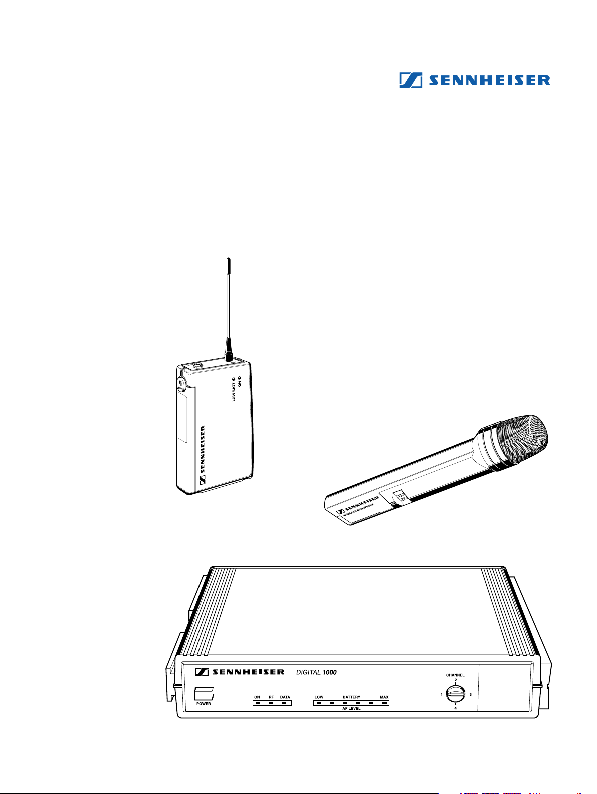
Congratulations
on your purchase of the Sennheiser Digital Wireless System. This is a stateof-the-art 900 MHz (UHF) digital audio transmission system and is capable
of outstanding audio and RF performance in combination with high-grade
amplification, mixing and recording systems.
Sennheiser proudly presents this advanced new standard in audio
transmission to musical and audio professionals as proof of Sennheiser’s
non-compromising pursuit of the ultimate in RF and audio performance.
Your digital wireless system is designed for superb audio quality and wireless
performance as well as continued reliability. To familiarize you with your
new digital wireless system, we suggest that you read through this entire
operation manual.
4
Page 5

2 Features
• 16-bit A/D–D/A conversion for CD quality sound.
• No compander ICs – for the transient response and “feel” of
a wired connection.
• Frequency Clear™ UHF Digital: System transmits a
proprietary digital signal on a 900 MHz UHF carrier for
freedom from multi-pathing and interference, including
HDTV.
• Quadiversity™ receiver – one UHF receiver, four internal
antennas, all microprocessor-controlled for freedom from
dropouts.
• Scanner-proof security: Proprietary digital transmission is
scanner-proof for eavesdrop-free peace of mind.
• Operating range of 80 – 130 feet under adverse conditions,
280 feet line of sight.
• Nine-segment LED display shows important performance
parameters including audio level and transmitter battery life.
This device complies with part 15 of the FCC rules. Operation is subject to
the following two conditions:
1 This device may not cause harmful interference, and
2 this device must accept any interference that may cause
undesired operation.
5
Page 6

3 Important notes
Never open electronic devices! This must only be done by authorized
personnel, especially for units connected to AC outlets. If devices are opened
by customers in breach of this instruction, the warranty becomes null and void.
Always disconnect the devices from the mains by removing the plug when
you wish to change connections or move the devices to a different place.
Never connect conventional RF antennas to the BNC sockets as these can
damage the receiver!
Keep the devices away from central heating radiators and electric heaters.
Never expose them to direct sunlight.
Use the devices in dry rooms only.
Use a damp cloth for cleaning the devices. Do not use any cleansing agents
or solvents.
4 System variants
Vocal Set 1091 DIGITAL
This system is ideal for vocal applications.
Set 1091 DIGITAL consists of: EM 1090 DIGITAL receiver, SKM 1091
DIGITAL handheld transmitter with supercardioid dynamic microphone
module, microphone clamp, plug-in mains unit, battery and operating manual.
Instrumental Set 1092 DIGITAL
This system is for connecting musical instruments (e.g. guitar) which have a
1/4” jack socket.
Set 1092 DIGITAL consists of: EM 1090 DIGITAL receiver, SK 1093
DIGITAL belt pack transmitter, instrument (guitar) cable, plug-in mains unit,
battery and operating manual.
Bodypack Set 1093 DIGITAL
This system is ideal for presentation and PA applications in acoustically
difficult rooms. The unobtrusive clip-on electret microphone (omnidirectional)
can be directed towards the speaker’s mouth.
Set 1093 DIGITAL consists of: EM 1090 DIGITAL receiver, SK 1093
DIGITAL belt pack transmitter, miniature clip-on electret microphone
(omnidirectional), plug-in mains unit, battery and operating manual.
6
Page 7
5 Preparing the devices for use
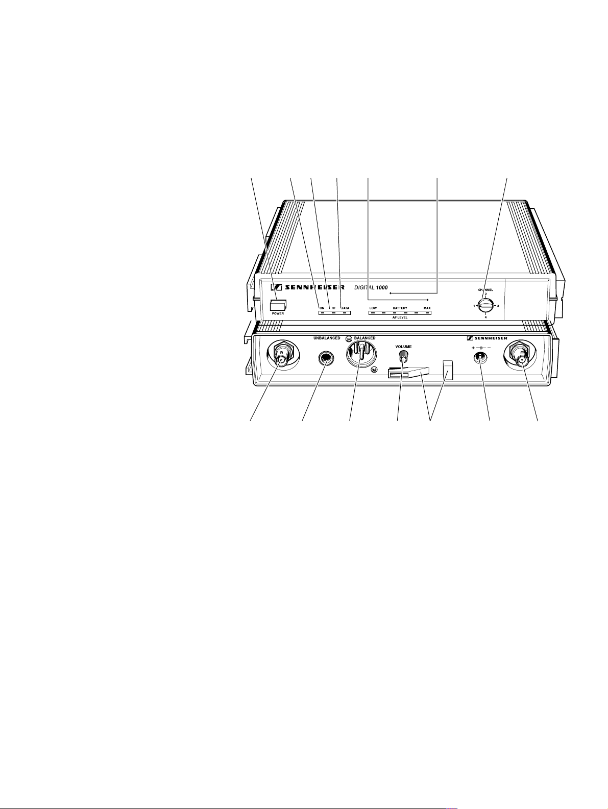
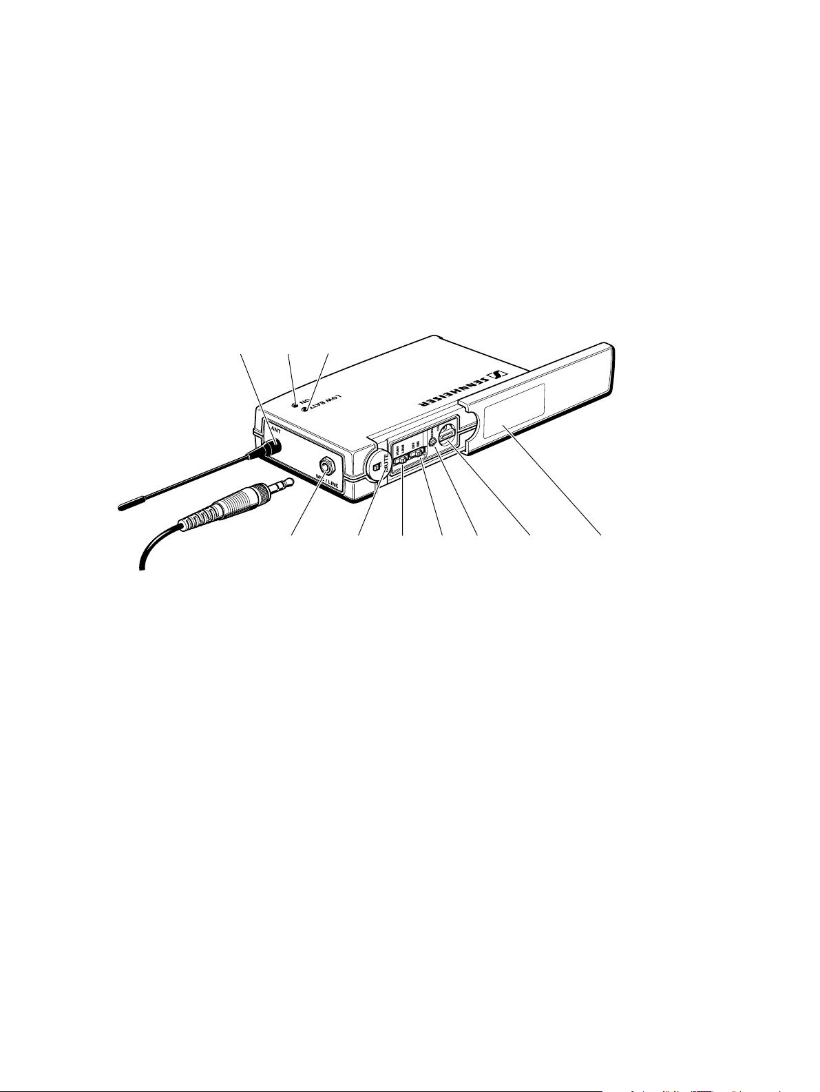
5.1 EM 1090 DIGITAL receiver
POWER button
“Power on/off” control LED
“RF” control LED
“Data” control LED
6-segment level display for
- incoming AF signal
- transmitter battery life
Channel selector switch
BNC socket 1 for connection of additional A 1090 DIGITAL antenna
AF output, unbalanced, 1/4” jack (line level)
AF output, balanced, XLR-3M
AF output level control (for outputs and )
Cable grip for power supply DC cable
DC socket for connection of mains unit
BNC socket 2 for connection of additional A 1090 DIGITAL antenna
7
Page 8
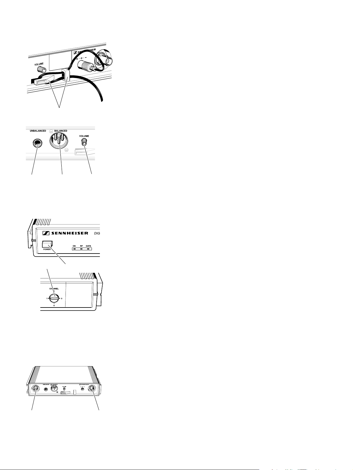
Connecting the mains unit
씰 Insert the DC connector on the power supply output cable into
socket (refer to page 7) at the rear of the receiver.
씰 Pass the cable through the cable grip .
Connecting the amplifier/mixing console
씰 Connect the amplifier/mixing console either
– to the XLR-3M socket or
– to the 1/4” jack socket .
Adjusting the AF output level
씰 Use the AF output level control to adjust the AF signal level that
appears at outputs and .
Switching the receiver on/off – Selecting a channel
씰 Press the POWER button to switch the receiver on.
씰 Use the channel selector switch to select a channel.
Connecting additional A 1090 DIGITAL antennas
Additional digital antennas can be connected to the BNC sockets and
if the range of the receiver’s internal antennas is not sufficient. This may
happen if receivers are mounted into a rack or are installed between metal
constructions on a stage.
For connecting the antennas, use 50 Ω coaxial cable with BNC connectors.
Ready made up antenna cables from Sennheiser are available as accessories
(see chapter 11).
Depending on the location you can connect one or two digital antennas.
Attention:
Never connect conventional RF antennas to the BNC sockets as these
can damage the receiver!
8
Page 9
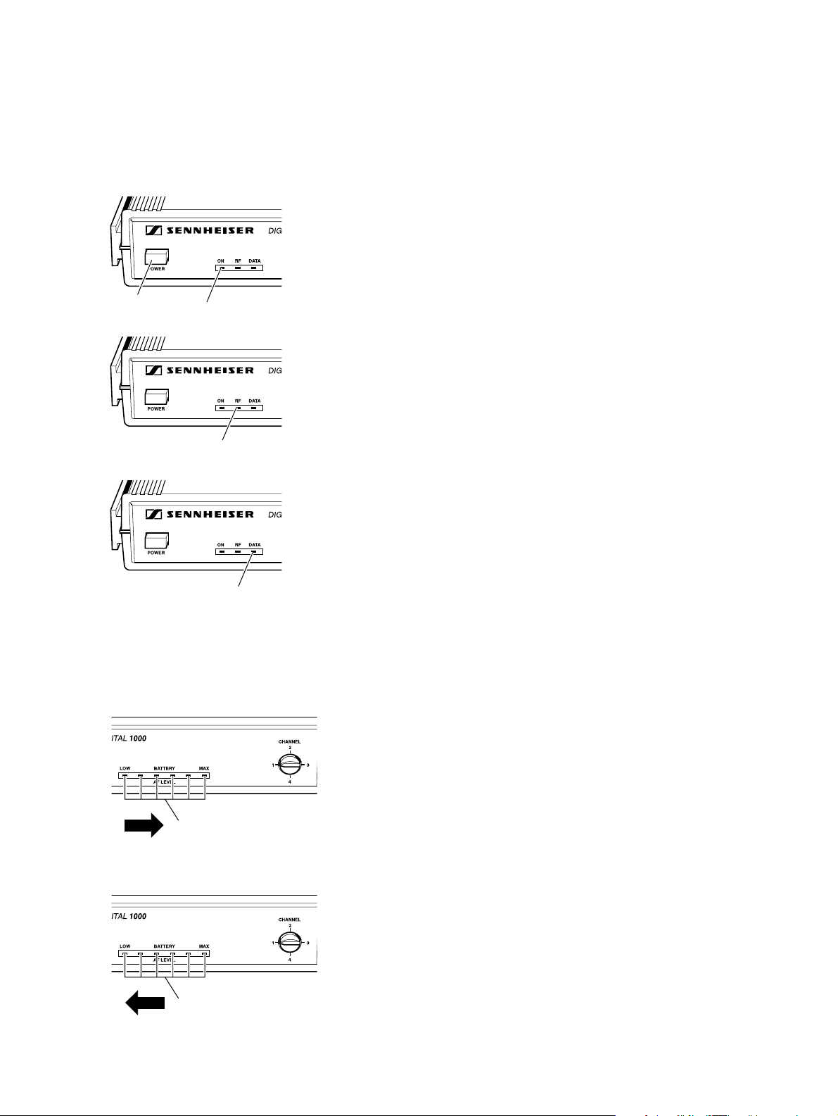
Indicators on the EM 1090 DIGITAL receiver
The 3-segment LED display on the left of the front panel provides information
on the operating state of the EM 1090 DIGITAL receiver:
Red LED “ON”:
The LED lights up to show that the receiver is connected to the mains
and has been switched on with the POWER button .
Red LED “RF”:
An RF signal from the suitable transmitter is being received by the receiver.
In contrast to analog transmission, digital test signals are also received so
that the transmitter can be identified.
Red LED “DATA”:
After the receiver has checked the suitable transmitter and accepted the digital transmission, the LED indicates that a data stream is being received.
“AF LEVEL” indication
The 6-segment LED display on the right of the front panel indicates the AF
level, i.e. the incoming audio signal. The segments of the LED display start
lighting up from the left.
Adjust the sensitivity of the SK 1093 DIGITAL belt pack transmitter such
that the last (right-hand) LED segment does not light up. The sensitivity of
the SKM 1091 DIGITAL handheld transmitter is automatically adjusted.
“BATTERY” indication
As long as the transmitter doesn’t transmit any audio signal (e.g. during
pauses in speaking), the 6-segment LED display indicates the remaining
transmitter battery capacity. The segments of the LED display start lighting
up from the right.
If the battery is going flat, the last (left-hand) LED segment will light up. You
should replace the battery within the next 20 minutes (value depending on
battery type).
9
Page 10
5.2 SK 1093 DIGITAL belt pack transmitter
Antenna
Operation indicator (green LED)
Battery life indicator (red LED)
AF input (MIC/LINE), 1/8” jack socket
Mute switch
HIGH/LOW dynamic window switch
ON/OFF switch
Control for precise sensitivity adjustment
Channel selector switch
Cover plate
10
Page 11
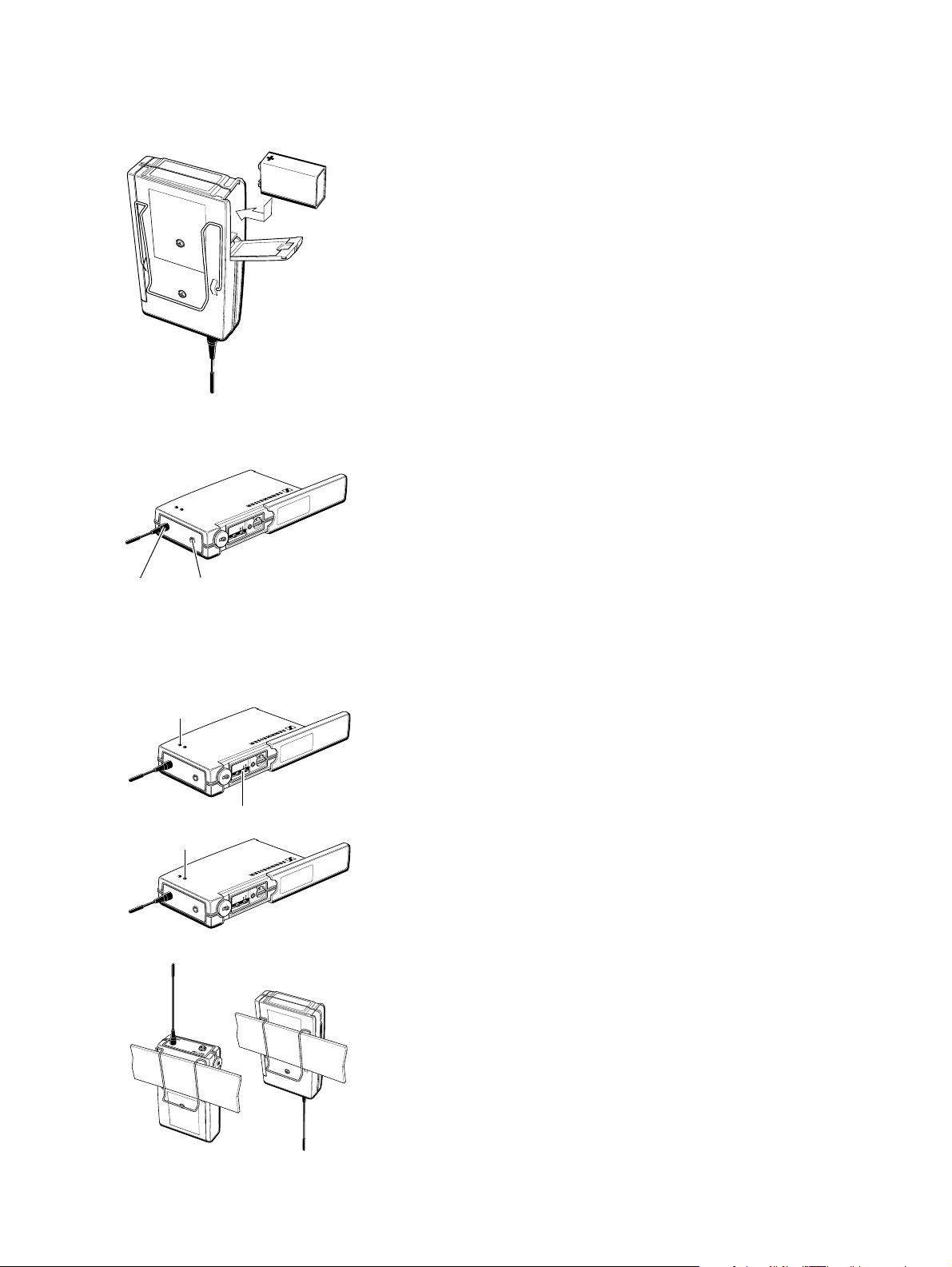
Inserting and changing the battery
씰 Slide the cover of the battery compartment in the direction of
the embossed arrow until it clicks audibly.
씰 Open the cover.
씰 Insert the 9 V PP3 battery (IEC 6 LR 61). Please observe
correct polarity when inserting the battery.
씰 Close the battery compartment.
씰 To remove the battery, push the small red lever in the battery
compartment towards the bottom side of the transmitter.
Note:
We recommend powering the transmitter by a standard PP3
alkaline battery. If powered by a rechargeable 9 V battery, the
operating time will be drastically reduced.
Connecting the antenna
씰 Screw the antenna onto the antenna socket (M3 connection).
Connecting the microphone/line cable
Electret powering (“plug-in” power) is available at the AF input for powering
the microphone.
씰 Connect the 1/8” jack plug from the microphone/line cable to the AF
input .
씰 Lock the jack plug by screwing down the locking ring.
Switching the transmitter on/off
씰 Slide back the cover plate.
씰 Set the ON/OFF switch to ON. The green LED lights up.
Battery life indication
The red LED provides information on the battery life. LED lit up:
The battery is going flat! You should replace the battery within the next 20
minutes (value depending on battery type).
Attachment of the transmitter to clothing
씰 The belt pack transmitter is best attached to e.g. the belt with the
supplied clip.
씰 The clip is detachable so that you can also attach the transmitter with
the antenna pointing downwards. To do so, withdraw the clip from
its fixing points and attach it the other way round.
11
Page 12
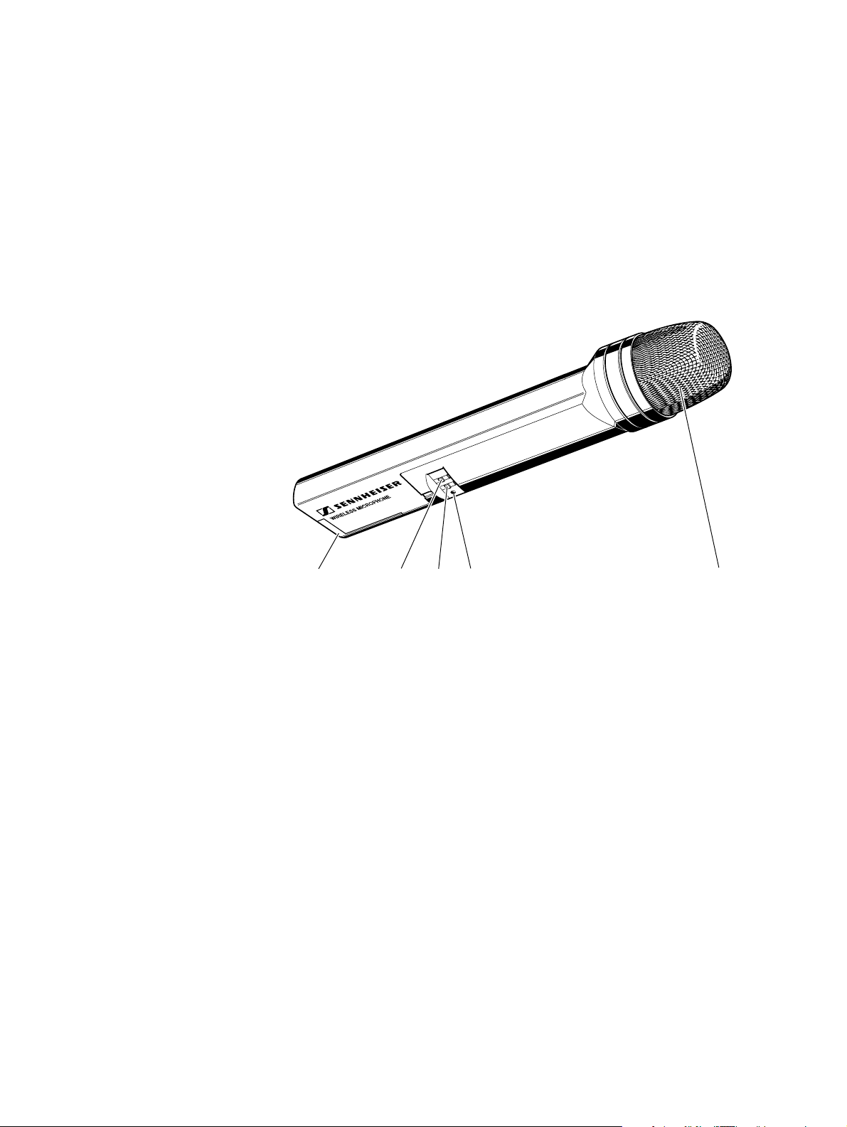
5.3 SKM 1091 DIGITAL handheld transmitter
Battery compartment
HIGH/LOW dynamic window switch
ON/OFF switch
Power control LED
Removeable sound inlet basket
12
Page 13
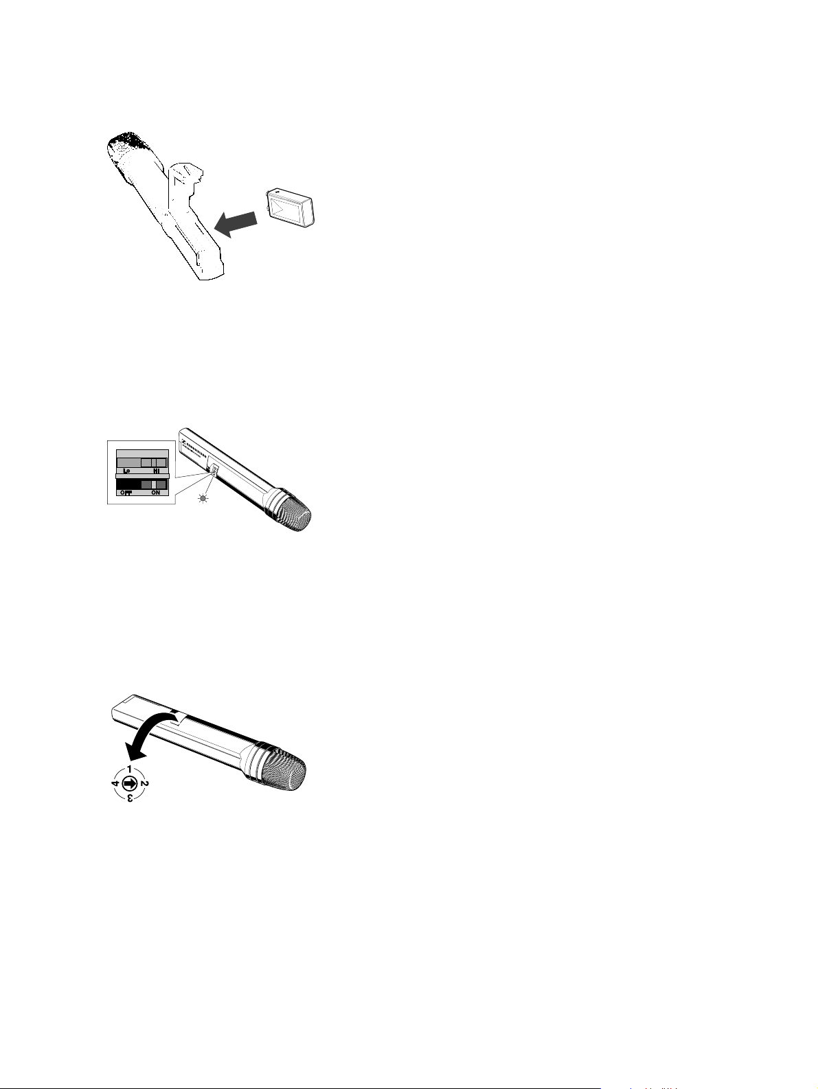
Inserting the battery
Open the battery compartment and insert the battery, taking care to observe
the correct polarity.
IEC 6 LR 61
씰 Please use type 9 V PP3 (IEC 6 LR 61) alkaline batteries. They ensure
an operating time of approx. 4 hours (value depending on battery
type).
씰 N.B.: Using NiCd rechargeable batteries is unadvisable as this would
reduce operating time to under two hours (technical data are not
affected).
Switching on the handheld transmitter
Switch on the SKM 1091 DIGITAL handheld transmitter by setting the
ON/OFF switch to ON.
After a short time, the red LED below the ON/OFF switch will light up,
indicating that the handheld transmitter is now ready for operation.
Selecting a transmission channel
Use the rotary switch at the side of the handheld transmitter to choose one
of the 4 possible transmission channels. The corresponding transmission
frequencies are listed on a sticker in the battery compartment.
Transmitter and receiver must operate on the same channel!
13
Page 14

6 Troubleshooting
씰 The transmission fails completely
Short-period switching off and back on again the EM 1090 DIGITAL
receiver may lead to an interrupt in transmission.
After having switched off the receiver hang on for a couple of seconds
before switching on again as with any processor-controlled device.
씰 The transmission range is not sufficient
Use remote antennas. You can connect two additional A 1090 DIGITAL
antennas to the EM 1090 DIGITAL receiver. The remote antennas
can be installed at a distance of up to 30 meters from the receiver.
씰 You can hear crackling noise and – occasionally – another
transmitter is being received
A second DIGITAL transmitter is operating on the same transmission
frequency. In contrast to analog audio transmission, both transmitters
are received simultaneously. If the field strengths of both transmitters
are almost similar, the receiver switches to and fro between the two
transmitters – crackling noise occurs – and possibly, the “DATA”- LED
goes off.
Choose a different transmission channel.
씰 You can hear “crosstalk”
Observe a minimum distance of 3 meters between transmitter and
receiver.
씰 Crackling noise and dropouts occur during the operation
with a clip-on microphone
The jack plug from the microphone cable is not screwed tightly to the
SK 1093 DIGITAL. Lock the jack plug by screwing down the locking
ring.
씰 Before deciding on a transmission channel, test – with the receiver
only – whether the chosen channel is free. Switch on the receiver and
listen to the channel. When you are sure that no one else is occupying
this channel, you can set the radiomicrophone to the same frequency.
7 Installation in a 19" rack
Slide the supplied rack mount adapters and two receivers together as
illustrated. The receivers can now be bolted into the rack.
14
Instead of a second EM 1090 DIGITAL receiver you can also use a
GA 1031 CC blank module or a GA 1031 AM antenna mount.
Page 15
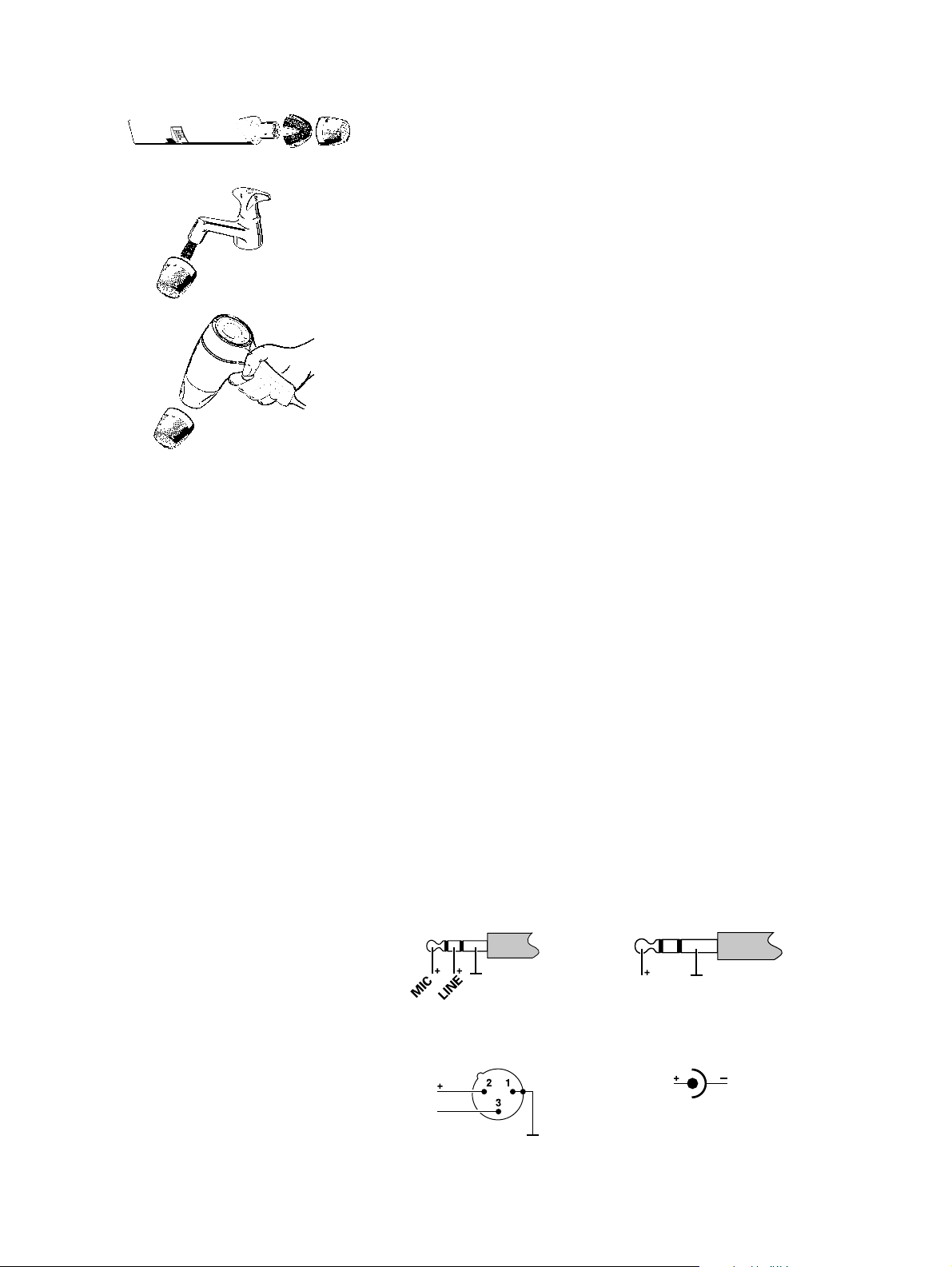
8 Care and maintenance
SKM 1091 DIGITAL handheld transmitter
The SKM 1091 DIGITAL’s sound inlet basket should be cleaned from time to
time.
씰 Unscrew the inlet basket (turn anti-clockwise) and remove it.
씰 Rinse foam protection and sound inlet basket with warm water.
씰 Dry both foam protection and sound inlet basket with a hairdryer.
Note:
Do not use any cleansing agents or solvents. Do not touch the microphone contacts.
Take off the sound inlet basket carefully in a straight line taking care
of the microphone capsule!
씰 Screw the sound inlet basket back tight on the SKM 1091 DIGITAL
transmitter.
9 Connector assignment
1/8” stereo jack plug 1/4” jack plug, unbalanced,
(lockable), SK 1093 EM 1090
XLR-3 connector, balanced, DC connector/Power supply
EM 1090
15
Page 16

10 Technical data
Overall system
Transmission format Sennheiser proprietary digital
audio transmission
Frequency response 20 Hz to 15 kHz
Audio dynamic range > 120 dB
Distortion < 0.2 % THD
RF carrier frequency 905 MHz to 925 MHz
Number of selectable frequencies 4
Channel 1 905 MHz
Channel 2 915 MHz
Channel 3 920 MHz
Channel 4 925 MHz
RF output power 0.5 mW
Signal-to-noise ratio > 110 dB(A)
Transmission range 280 feet line of sight
80 to 130 feet adverse conditions
FCC Approval Part 15 approved, no user licence
required
SK 1093 DIGITAL & SKM 1091 DIGITAL Transmitter
A/D conversion 18-bit linear, 128 fold oversampling
Input impedance LINE 1 MOhm
Input impedance MIC 930 Ohm to 6,000 Ohm
Connectors (SK 1093 DIGITAL) Lockable 1/8”, unbalanced
Controls Mute, Power on/off, Channel Select,
Sensitivity adjustment
Dimensions SK 1093 DIGITAL 105 x 63 x 26 mm
Dimensions SKM 1091 DIGITAL 245 x 38 mm
EM 1090 DIGITAL Receiver
D/A conversion 16-bit linear
Output Balanced +18 dBU (-2 dB), 150 Ohm
Unbalanced +12 dBU (-2 dB), 1.6 kOhm
Connectors Transformerless XLR, balanced
1/4” jack, unbalanced
Indicators Power on/off,
Transmitter Battery Life,
Data Received, RF
Controls Power on/off, Channel Select,
AF Level
Dimensions 213 x 145 x 44 mm – (1/2 RU)
Power supply 12 V DC
16
Page 17

11 Accessories
GA 1031 CC Blank module, can be used
(Cat. no. 04253) instead of a receiver for installation
in a 19” rack
GA 1031 AM Antenna mount, permits the
(Cat. no. 04254) connection of antennas to the front
of the rack.
Attention:
Only connect A 1090 DIGITAL
antennas to the GA 1031 AM
antenna mount!
A 1090 DIGITAL Digital antenna, 4-diversity
(Cat. no. 04928)
GZL 1019 A5 BNC/BNC antenna cable, 5 m
(Cat. no. 02325)
GZL 1019 A10 BNC/BNC antenna cable, 10 m
(Cat. no. 02326)
NG 1031-US Plug-in mains unit, US version
(Cat. no. 03649)
17
Page 18

18
Page 19

NOTICE D‘EMPLOI
WIRELESS DIGITAL
19
Page 20

1 Sommaire
Chap. Contenu ................................................................................................ Page
1 Sommaire.......................................................................................20
2 Points forts.....................................................................................21
3 Remarques importantes ................................................................ 22
4 Variantes ........................................................................................22
5 Préparation à l’utilisation..............................................................23
5.1 Récepteur EM 1090 DIGITAL............................................ 23
5.2 Emetteur de poche SK 1093 DIGITAL .............................. 26
5.3 Emetteur à main SKM 1091 DIGITAL ..............................28
6 Anomalies de fonctionnement......................................................30
7 Montage en rack 19" .................................................................... 30
8 Entretien et maintenance ..............................................................31
9 Câblage des connecteurs .............................................................. 31
10 Caractéristiques.............................................................................32
11 Accessoires.....................................................................................33
20
Félicitations
pour votre achat d’un système sans fil Digital Sennheiser. Il s’agit d’un système
de transmission audio numérique 900 MHz (UHF) au top actuel de la
technologie. Il est doté de performances BF et HF hors du commun, en
parfait accord avec les systèmes de sonorisation, de mixage et d’enregistrement
haut de gamme.
Sennheiser est fier d’introduire un nouveau standard high tech de transmission
audio pour les musiciens et les professionnels du son. C’est également
l’illustration de notre indéfectible volonté de poursuivre notre quête de l’absolu
en matière de performances HF et audio.
Votre système de transmission sans fil numérique est conçu pour vous offrir
une superbe qualité audio et des performances de transmission gages d’une
exceptionnelle fiabilité. Afin de vous familiariser avec votre système de
transmission sans fil numérique, nous vous suggérons de passer quelques
instants à la lecture de ce manuel d’utilisation.
Page 21

2 Points forts
• Conversion A/D - D/A 16 bits pour une qualité sonore type CD
• Pas de compander pour une réponse transitoire et un
“feeling” comparables à une liaison par câble.
• “Frequency Clear™” UHF Digital : Système breveté de
trans-mission numérique du signal dans la bande UHF
900 MHz libérant de toute interférence y compris HDTV.
• Récepteur “Quadiversity™” - un récepteur UHF doté de
quatre antennes internes, entièrement contrôlé par
microprocesseur, permettant d’éviter tout “dropout”.
• Scanner : système de transmission numérique exclusif avec
fonction scanner permettant d’éviter tout incident de transmission.
• Rayon d’action de 20 à 40 mètres en conditions difficiles et
de plus de 80 m en champ libre.
• Affichage LED à 9 segments permettant de visualiser les
paramètres de fonctionnement importants tels que niveau
audio et état des piles de l’émetteur.
Cet appareil est en conformité avec l’article 15 de la norme FCC. Son
utilisation doit satisfaire à deux conditions :
1 Cet appareil ne doit pas causer d’interférences indésirables, et
2 il ne doit être sensible à aucune interférence pouvant causer
un fonctionnement inadéquat.
21
Page 22

3 Remarques importantes
Ne jamais ouvrir les appareils électroniques! Cette opération ne doit être
effectuée que par un personnel qualifié. Cela est particulièrement important
lorsqu’il s’agit d’un appareil relié au secteur. L’ouverture d’un appareil par
l’utilisateur entraîne la nullité de la garantie.
Toujours débrancher l’appareil du secteur avant de modifier les raccordements
ou pour le changer de place.
Ne jamais raccorder des antennes HF conventionnelles aux prises BNC, le
récepteur pouvant dans ce cas être endommagé !
Eloigner l’appareil de toute source de chaleur telle que radiateur de chauffage
central ou électrique. Ne pas exposer directement sous un projecteur.
Utiliser l’appareil dans des endroits exempts d’humidité.
Utiliser un chiffon doux pour nettoyer l’appareil. Ne pas utiliser de détergents
ou de solvants.
4 Variantes
Set vocal 1091 DIGITAL
Ce système est idéal pour les applications vocales.
Le Set 1091 DIGITAL se compose de : récepteur EM 1090 DIGITAL,
émetteur à main SKM 1091 DIGITAL avec microphone dynamique supercardioïde, pince micro, bloc secteur, pile et notice d’emploi.
Set instrumental 1092 DIGITAL
Ce système est prévu pour être raccordé directement à un instrument de
musique (ex: guitare) grâce à un jack 1/4".
Le Set 1092 Digital se compose de : récepteur EM 1090 DIGITAL, émetteur
de ceinture SK 1093 DIGITAL, câble instrument (guitare), bloc secteur, pile
et notice d’emploi.
Set de poche 1093 DIGITAL
Ce système est idéal pour les animateurs et les applications public-adress
dans des lieux à l’acoustique difficile. Le microphone électret (omnidirectionnel) peut être placé à proximité directe des lèvres de l’utilisateur.
Le Set 1093 Digital se compose de : récepteur EM 1090 DIGITAL, émetteur
de ceinture SK 1093 DIGITAL, microphone cravate miniature à électret
(omnidirectionnel), bloc secteur, pile et notice d’emploi.
22
Page 23

5 Préparation à l’utilisation
5.1 Récepteur EM 1090 DIGITAL
Bouton de mise sous tension
LED de contrôle M/A (“ON”)
LED de contrôle “RF”
LED de contrôle “DATA”
Afficheur de niveau 6 segments pour
- signal BF entrant
- état de la pile de l’émetteur
Sélecteur de canal
Prise BNC 1 pour le raccordement d’une antenne A 1090 DIGITAL
supplémentaire
Sortie BF, asymétrique, jack 1/4" (niveau ligne)
Sortie BF, symétrique, XLR-3 M
Réglage de niveau de sortie BF (pour sorties et )
Clip pour câble du bloc secteur
Prise d’alimentation pour raccordement du bloc secteur
Prise BNC 2 pour le raccordement d’une antenne A 1090 DIGITAL
supplémentaire
23
Page 24

Raccordement de l’alimentation secteur
씰 Insérer le connecteur du câble venant du bloc secteur dans la prise
(voir page 23) à l’arrière du récepteur.
씰 Passer le câble comme indiqué dans le clip de fixation .
Raccordement d’une console de mixage/amplificateur
씰 Raccorder la console de mixage/amplificateur soit
- à la prise XLR-3 ou
- à la prise jack 1/4" .
Ajustement du niveau de sortie BF
씰 Utilisez le réglage de niveau de sortie BF afin d’ajuster le niveau
du signal BF présent aux sorties et .
Commutation M/A du récepteur - Sélection d’un canal
씰 Appuyer sur le bouton POWER pour mettre en marche le récepteur.
씰 Utiliser le sélecteur de canal pour choisir un canal.
Raccordement d’antennes supplémentaires A 1090 DIGITAL
Des antennes supplémentaires peuvent être raccordées aux prises BNC
et si les antennes intégrées au récepteur s’avèrent insuffisantes. Cela peut
être le cas si les récepteurs sont montés en rack ou placés à proximité de
structures métalliques sur scène.
Pour raccorder les antennes, utiliser du câble coaxial RG 58 d’impédance 50 Ω
doté de connecteurs BNC. Des câbles Sennheiser adéquats sont disponibles
en accessoires (voir chapitre 11).
Selon les conditions vous pouvez raccorder une ou deux antennes digitales.
24
Attention:
Ne jamais raccorder des antennes HF conventionnelles aux prises BNC,
le récepteur pouvant dans ce cas être endommagé !
Page 25

Indicateurs présents sur le récepteur EM 1090 DIGITAL
L’affichage LED à 3 segments à la gauche de la façade donne les informations
suivantes sur le mode de fonctionnement du récepteur EM 1090 DIGITAL :
LED rouge “ON” :
La LED s’allume pour indiquer que le récepteur est raccordé à son
alimentation et a été commuté sur marche avec le bouton POWER .
LED rouge “RF” :
Un signal HF provenant d’un émetteur adéquat est reçu par le récepteur.
Par rapport à une transmission analogique, les tests de signal sont également
reçus de façon que l’émetteur puisse être identifié.
LED rouge “DATA” :
Après que le récepteur a testé l’émetteur adéquat et accepté la transmission
numérique, la LED indique si le train d’informations numériques est
bien reçu.
Indication “AF LEVEL“ (“NIVEAU BF“) :
L’affichage LED à 6 segments à la droite de la façade indique le niveau BF,
par ex. le niveau de signal audio entrant. L’affichage LED s’illumine à partir
de la gauche.
Régler la sensibilité de l’émetteur de ceinture SK 1093 DIGITAL de façon
que le dernier segment LED (à droite) ne s’allume pas. La sensibilité de
l’émetteur à main SKM 1091 DIGITAL s’ajuste automatiquement.
Indication “BATTERY” (“PILE“) :
Aussi longtemps que l’émetteur ne transmet aucun signal audio (ex: durant
les pauses dans un speaking), l’affichage LED à 6 segments indique la capacité
restante de la pile de l’émetteur. L’affichage LED s’illumine à partir de la
droite.
Si la pile est presque vide, le dernier segment LED (à gauche) restera allumé.
Vous devez remplacer la pile concernée dans les 20 minutes (valeur
dépendante du type de piles).
25
Page 26

5.2 Emetteur de ceinture SK 1093 DIGITAL
Antenne
Indicateur de fonctionnement (LED verte)
Indicateur d’état de la pile (LED rouge)
Entrée BF (MIC/LIGNE), jack 1/8"
Bouton mute
Commutateur de sensibilité
Commutateur M/A
Potentiomètre réglage fin de sensibilité
Sélecteur de canal
Capot de protection
26
Page 27

Mise en place et changement de la pile
씰 Faire coulisser le couvercle du compartiment pile dans le sens de la
flèche jusqu’à un clic audible.
씰 Ouvrir le couvercle.
씰 Insérer une pile de 9 V PP3 (IEC 6 LR6 61). Veillez à respecter la
polarité lorsque vous insérez la pile.
씰 Refermer le compartiment pile.
씰 Pour retirer la pile, appuyer sur le petit levier rouge placé dans le
compartiment pile contre la paroi inférieure de l’émetteur.
Note :
Il est recommandé d’utiliser pour l’émetteur des piles de type PP3
alcalines. Si des piles rechargeables sont utilisées, l’autonomie sera
considérablement réduite.
Raccordement de l’antenne
씰 Visser l’antenne dans la prise (connexion M3) prévue à cet effet.
Raccordement du câble micro/câble ligne
Alimentation électret (alim. “plug-in“) disponible à l’entrée BF pour
l’alimentation du microphone.
씰 Raccorder le jack 1/8" venant du micro/câble ligne à l’entrée BF .
씰 Verrouiller le jack en tournant la bague de verrouillage.
Commuter l’émetteur en Marche/Arrêt
씰 Faire coulisser le capot de protection.
씰 Placer le commutateur M/A en position ON (marche). La LED
verte s’allume.
Indication de la capacité de la pile
La LED rouge indique l’état de la pile. LED allumée : la pile est
presque vide ! Vous devez la remplacer dans les 20 minutes (valeur dépendante
du type de piles).
Fixation de l’émetteur aux vêtements
씰 L’émetteur de ceinture sera idéalement placé à la ceinture grâce au
clip fourni.
씰 Le clip est amovible de façon à permettre également de placer
l’émetteur, antenne vers le bas. Il est également possible de retirer le
clip et de fixer l’émetteur de la façon qui vous convient.
27
Page 28

5.3 Emetteur à main SKM 1091 DIGITAL
Compartiment pile
Commutateur de sensibilité
Commutateur M/A
LED de contrôle d’alimentation
Grille de protection amovible
28
Page 29

Mise en place de la pile
Ouvrir le compartiment pile et insérer la pile en veillant à respecter la polarité.
IEC 6 LR 61
씰 Veuillez utiliser une pile alcaline de type 9 V PP3 (IEC 6 LR 61). Elle
assure une autonomie d’environ 4 heures (valeur dépendante du type
de piles).
씰 N.B.: L’utilisation d’un accu NiCd rechargeable n’est pas souhaitable,
l’autonomie se trouvant réduite à environ 2 heures (les caractéristiques
ne sont pas affectées).
Mise en marche de l’émetteur à main
Placer sur ON (marche) le commutateur M/A du SKM 1091 DIGITAL.
Après un court instant, la LED rouge , sous le commutateur M/A, s’allume,
signalant que l’émetteur à main est opérationnel.
Sélection d’un canal de transmission
Utiliser le commutateur rotatif sur le côté de l’émetteur à main pour choisir
un des 4 canaux de transmission possibles. Les fréquences de transmission
correspondantes sont listées sur un sticker placé dans le compartiment pile.
Emetteur et récepteur doivent utiliser le même canal.
29
Page 30

6 Anomalies de fonctionnement
씰 La transmission échoue totalement
Commuter le récepteur EM 1090 DIGITAL sur off pendant un bref
instant puis le remettre à nouveau en fonction peut entraîner une
interruption de la transmission.
Après avoir commuté sur off le récepteur, attendre deux ou trois
secondes avant de le remettre en marche comme pour tout appareil
géré par microprocesseur.
씰 La portée de la transmission n’est pas suffisante
Utiliser une antenne déportée. Vous pouvez connecter deux antennes
A 1090 DIGITAL supplémentaires au récepteur EM 1090 DIGITAL.
Les antennes déportées peuvent être installées à une distance pouvant
aller jusqu’à 30 mètres du récepteur.
씰 Vous entendez des bruits de craquements et - occasionnellement -
d’autres émetteurs sont captés
Un second émetteur DIGITAL utilise la même fréquence de transmission. Contrairement à une transmission audio analogique, deux
émetteurs sont reçus simultanément. Si le champ de deux émetteurs
est d’intensités comparables, le récepteur se commute de l’un à l’autre,
des bruits de craquements en étant la conséquence. Il est possible
également que la LED “DATA” s’éteigne.
Choisir un autre canal de transmission.
씰 Vous entendez de la diaphonie
Observez une distance minimum de 3 mètres entre émetteur et
récepteur.
씰 Des craquements et des dropouts apparaissent lors de l’utilisation d’un
micro cravate
Le jack n’est pas fermement verrouillé sur le SK 1093 DIGITAL.
Vérifier le verrouillage de la bague.
씰 Avant de décider de l’utilisation d’un canal, tester - avec le récepteur
seul - que ce canal est bien libre. Commuter le récepteur sur le canal
envisagé et écouter. Lorsque vous êtes certain que ce canal n’est pas
utilisé, vous pouvez régler l’émetteur sur la même fréquence.
7 Montage en rack 19"
Faites coulisser les adaptateurs fournis comme indiqué ci-contre pour les
fixer sur les deux récepteurs. Les récepteurs peuvent ensuite être fixés dans
le rack.
En l’absence d’un deuxième récepteur EM 1090 DIGITAL, vous pouvez
utiliser un module cache GA 1031 CC ou un support d’antenne GA 1031 AM.
30
Page 31

8 Entretien et maintenance
Emetteur à main SKM 1091 DIGITAL
La grille de protection du SKM 1091 DIGITAL doit être nettoyée de temps
en temps.
씰 Dévisser la grille (dans le sens inverse des aiguilles d’une montre) et
la déposer.
씰 Rincer la mousse de protection et la grille avec de l’eau chaude.
씰 Sécher mousse et grille à l’aide d’un sèche-cheveux.
Note:
Ne pas utiliser de détergent ou de solvant. Ne pas toucher les contacts
de la capsule du micro!
Seule la grille de protection doit être démontée. Ne pas toucher à la
capsule et ne pas tenter de la nettoyer!
씰 Remettre en place la grille de protection sur le SKM 1091 DIGITAL
en la revissant à fond.
9 Câblage des connecteurs
Jack stéréo 1/8" Jack 1/4", asymétrique,
(verrouillable), SK 1093 EM 1090
Connecteur XLR-3, Connecteur CC / Alimentation
symétrique, EM 1090
31
Page 32

10 Caractéristiques
Généralités
Format de transmission Transmission audio numérique
brevetée Sennheiser
Réponse en fréquence 20 Hz - 15 kHz
Dynamique > 120 dB
Distorsion < 0,2 % DHT
Fréquences porteuses 905 - 925 MHz
Nombre de fréquences commutables 4
Canal 1 905 MHz
Canal 2 915 MHz
Canal 3 920 MHz
Canal 4 925 MHz
Puissance HF 0,5 mW
Rapport S/B > 110 dB(A)
Portée 85 m en champ libre
20 à 40 m en conditions difficiles
Conformité FCC conforme aux spécifications de
l’article 15, pas de licence
d’utilisation
Emetteurs SK 1093 DIGITAL et SKM 1091 DIGITAL
Conversion A/D 18 bits linéaire,
suréchantillonnage 128 x
Impédance d’entrée ligne 1 MOhm
Impédance d’entrée micro 930 à 6.000 Ohms
Connecteurs (SK 1093 Digital) verrouillable 1/8", asymétrique
Contrôles Mute, M/A, sélect. canal, sensibilité
Dimensions SK 1093 Digital 105 x 63 x 26 mm
Dimensions SKM 1091 Digital 245 x 38 mm
Récepteur EM 1090 DIGITAL
Conversion D/A 16 bits linéaire
Sorties symétrique +18 dBU (-2 dB), 150 Ohm
asymétrique +12 dBU (-2 dB), 1,6 kOhms
Connecteurs XLR sans transformateur, symétrique
jack 1/4", asymétrique
Indicateurs M/A, état pile, réception data, HF
Contrôles M/A, sélect. canal, niveau BF
Dimensions 213 x 145 x 44 mm (1/2 U 19")
Alimentation 12 V CC
32
Page 33

11 Accessoires
GA 1031 CC Module cache pouvant remplacer
(N° Réf. 04253) un récepteur dans le cas d’un
montage en rack 19".
GA 1031 AM Support d’antenne permettant le
(N° Réf. 04254) montage des antennes en façade
d’un rack.
Attention :
Ne raccorder que des antennes
A 1090 DIGITAL au
support d’antenne GA 1031 AM !
A 1090 DIGITAL Antenne digitale, 4-diversity
(N° Réf. 04928)
GZL 1019 A5 Câble d’antenne BNC/BNC de 5 m
(N° Réf. 02325)
GZL 1019 A10 Câble d’antenne BNC/BNC de 10 m
(N° Réf. 02326)
NG 1081-US Bloc secteur, version US
(N° Réf. 03649)
33
Page 34

34
Page 35

INSTRUCCIONES PARA EL USO
WIRELESS DIGITAL
35
Page 36

1 Contenido
Cap. Contenido .......................................................................................... Página
1 Contenido......................................................................................36
2 Características ............................................................................... 37
3 Notas importantes ......................................................................... 38
4 Variaciones del sistema .................................................................38
5 Preparación del equipo antes del uso .......................................... 39
5.1 Receptor EM 1090 DIGITAL ............................................. 39
5.2 Transmisor de bolsillo SK 1093 DIGITAL ........................ 42
5.3 Transmisor de mano SKM 1091 DIGITAL .......................44
6 Solución de problemas..................................................................46
7 Instalación en rack de 19" ............................................................46
8 Cuidado y mantención .................................................................47
9 Asignación de conectores ............................................................. 47
10 Información técnica ...................................................................... 48
11 Accesorios......................................................................................49
36
Felicitaciones
por la adquisición del Sistema lnalámbrico Digital Sennheiser. Se trata de un
sistema de transmisión de audio digitál de 900 MHz (UHF), fabricado con
tecnología de punta y capaz de un rendimiento RF y de audio sorprendentes,
en combinación con sistemas de grabación, amplificación y mezcla de alta
calidad.
Sennheiser se enorgullece en presentar este nuevo y avanzado sistema de
transmisión de audio a músicos y profesionales del sonido como prueba de
la inalcanzable búsqueda de lo más avanzado en rendimiento de audio y RF
(frecuencia de radio).
Su sistema inalámbrico digital está diseñado para una calidad de audio y un
desempeño inalámbrico inigualables, así como una seguridad del funcionamiento que perdurará en el tiempo. Para familiarizarse con su nuevo sistema
inalámbrico digital, le sugerimos que lea todo este manual de funcionamiento.
Page 37

2 Características
• Conversión de 16-bit A/D-D/A para calidad de audio CD.
• Circuitos sin compander – para una respuesta de transientes y
“sensación” sonora comparable a la de una conexión por cable.
• UHF Digital Frecuency Clear™ (Frecuencia Clara): El sistema
transmite una señal digital específica de este equipo usando un
portador UHF de 900 MHz para ser más independiente de
multi-líneas e interferencias, incluyendo HDTV.
• Receptor Quadiversity™ (Diversidad cuádruple): Un receptor
UHF, cuatro antenas, todas controladas por microprocesador para
evitar cortes en la recepción.
• Seguridad a prueba de scanner. La transmisión digital específica de
este equipo es a prueba de scanner para estar a salvo de que se pueda
escuchar furtivamente.
• Rango de funcionamiento entre 25 a 40 m ó 80 a 130 pies bajo
condiciones adversas; 85 m ó 280 pies en línea de visión.
• La pantalla de nueve luces (LEDs) muestra importantes parámetros
de rendimiento, incluyendo niveles de audio y vida útil de la batería
del transmisor.
Este aparato cumple con la sección N° 15 de las reglas de la FCC (Comísión
Federal de Comunicaciones de EEUU). La operación está sujeta a las
siguientes dos condiciones:
1 El aparato no provoca interferencias dañinas y
2 este aparato aceptará cualquier interferencia que pueda provocar el
funcionamiento inadecuado del mismo.
37
Page 38

3 Notas importantes
¡No abra nunca los aparatos electrónicos! Esto sólo puede ser realizado por
personal autorizado y es particularmente importante para unidades conectadas
a tomas de corriente AC. Si Ud. abre el aparato en violación de esta
instrucción, la garantía del producto quedará anulada.
Desconecte siempre el aparato de su fuente de energía, desconectando el
enchufe cuando desee cambiar conexiones o moverlo a otro lugar.
¡Nunca conecte antenas RF convencionales a los conectores BNC porque
puede dañar el receptor!
Mantenga el aparato alejado de la calefacción central o calefactores eléctricos.
Nunca lo exponga a la luz de sol directa.
Utilice los aparatos sólo en habitaciones secas.
Utilice un paño húmedo para limpiar. No use ningún solvente ni limpiador.
4 Variaciones del sistema
Set 1091 DIGITAL Vocal
Este sistema es ideal para aplicaciones vocales.
El Set 1091 DIGITAL consiste en: receptor EM 1090 DIGITAL, transmisor
de mano SKM 1091 DIGITAL con módulo de micrófono dinámico
supercardioide, pinza para el micrófono, fuente de poder, baterías y manual
de funcionamiento.
Set 1092 DIGITAL Instrumental
Este sistema se utiliza para conectar instrumentos musicales (por ejemplo:
guitarra) que tienen un conector jack de 1/4".
El Set 1092 DIGITAL consiste en: receptor EM 1090 DIGITAL, transmisor
de bolsillo SK 1093 DIGITAL, cable para instrumento, fuente de poder,
baterías y manual de funcionamiento.
Set 1093 DIGITAL de Bolsillo
Este sistema es ideal para presentaciones y aplicaciones PA en salas acústicamente difíciles. Su micrófono de solapa (omnidireccional) se puede dirigír
hacia la boca del usuario.
El Set 1093 DIGITAL consiste en: receptor EM 1090 DIGITAL, transmisor
de bolsillo SK 1093 DIGITAL, micrófono miniatura (omnidireccional) tipo
lavalier o de solapa, fuente de poder, baterías y manual de funcionamiento.
38
Page 39

5 Preparación del equipo antes del uso
5.1 Receptor EM 1090 DIGITAL
Botón POWER
Luz (LED) de control “ON”
Luz (LED) de control “RF”
Luz (LED) de control “DATA”
Pantalla de nivel de 6 segmentos para
- señal AF entrante
- vida útil de la batería del transmisor
Selector de canal
Conector BNC 1 para conexión de antena A 1090 DIGITAL adicional
Salida AF, desbalanceada, jack de 1/4" (nivel de línea)
Salida AF, balanceada, XLR-3M
Control de nivel de salida AF (para salidas y )
Manija para cable CC de fuente de poder
Enchufe CC para conectar la fuente de poder
Conector BNC 2 para conectar antena A 1090 DIGITAL adicional
39
Page 40

Conexión de la fuente de poder
씰 Inserte el conector CC del cable de salida de la fuente de poder en el
enchufe (ver la página 39) que se encuentra en la parte posterior
del receptor.
씰 Pase el cable por la manija .
Conexión del amplificador o mezclador
씰 Conecte el amplificador o mezcla or ya sea:
- al enchufe XLR-3M o,
- al enchufe jack de 1/4" .
Ajuste del nivel de salida AF
Use el control de nivel de salida AF para ajustar el nivel de señal AF que
aparece en las salidas y .
Encendido/Apagado del receptor - Selección de canales
씰 Presione el botón POWER para encender el receptor.
씰 Utilice el selector de canal para seleccionar un canal.
Conexión adicional de antenas A 1090 DIGITAL
Si el rango de las antenas internas del receptor es insuficiente, es posible
conectar antenas digitales adicionales a los conectores BNC y . Esto
podría suceder si los receptores están montados en un rack o instalados
entre construcciones metálicas sobre un escenario.
Para conectar las antenas, utilice un cable coaxial RG 58 de 50 Ω con
conectores BNC. Sennheiser tiene disponibles como accesorios cables de
antena listos para usar (ver capítulo 11).
Dependiendo de la ubicación, usted puede conectar una o dos antenas
digitales.
40
Atención:
¡Nunca conecte antenas RF convencionales a los conectores BNC porque
puede dañar el receptor!
Page 41

lndicadores en el receptor EM 1090 DIGITAL
El panel de tres luces (LEDs) a la izquierda del panel frontal le proporciona
información acerca del estado operativo del receptor EM 1090 DIGITAL:
Luz roja “ON” (encendido):
La luz se enciende para mostrar que el receptor está conectado a la fuente
eléctrica y que el botón POWER ha sido prendido.
Luz roja “RF” (frecuencia de radio):
El receptor está recibiendo una señal RF del transmisor adecuado. A diferencia
de la transmisión analógica, también se reciben señales de prueba digitales
para que el transmisor pueda ser identificado.
Luz roja “DATA” (información):
Una vez que el receptor ha reconocido al transmisor y ha aceptado la
transmisión digital, la luz indica que se está recibiendo información.
Indicador “NIVEL AF” (frecuencia de audio):
El panel de seis luces (LEDs) a la derecha del panel frontal indica el nivel
AF; es decir, la señal de audio entrante. Los segmentos del panel comienzan
a activarse desde la izquierda.
Ajuste la sensibilidad del transmisor de bolsillo SK 1093 DIGITAL de modo
que la última luz (a la derecha) NO se encienda. La sensibilidad del transmisor
de mano SKM 1091 DIGITAL se ajusta de forma automática.
Indicador “BATERIA”
Mientras el transmisor no transmita alguna señal de audio (por ejemplo:
durante las pausas de un discurso), el panel de seis luces indica la capacidad
restante de la batería del transmisor. Las luces del panel comienzan a
encenderse desde la derecha.
Si la batería se agota, la última luz (a la izquierda) se encenderá. Usted deberá
reemplazar la batería dentro de los próximos 20 minutos (valor en función
del tipo de la batería).
41
Page 42

5.2 Transmisor de bolsillo SK 1093 DIGITAL
Antena
Indicador de operación (LED verde)
Indicador de vida de la batería (LED rojo)
Entrada AF (MIC/LINEA), conector jack de 1/8"
Interruptor Mute (silenciador)
Conmutador dinámico de ventana HIGH/LOW
Interruptor ON/OFF
Tornillo para ajuste preciso de sensibilidad
Selector de canal
Cubierta
42
Page 43

Insertar y cambiar la batería
씰 Deslice la cubierta del compartimiento para baterías en dirección de
la flecha indicadora hasta que haga un clic audible.
씰 Abra la cubierta.
씰 Inserte la batería de 9 V (IEC 6 LR 61). Por favor fíjese en la polaridad
correcta al insertar la batería.
씰 Cierre el compartimiento.
씰 Para sacar la batería, presione la palanca roja que se encuentra dentro
del compartimiento para baterías en dirección del fondo del transmisor.
NOTA:
Le recomendamos usar para su transmisor baterías PP3 alcalinas
estándar. Si utiliza una batería de 9 V recargable, el tiempo de operación
se verá drásticamente reducido.
Conexión de la antena
씰 Atornille la antena al enchufe (conexión M3).
Conexión del cable de micrófono/línea
La alimentación necesaria para el micrófono se encuentra disponible en la
entrada AF (encendido “plug-in”).
씰 Enchufe el conector jack de 1/8" del cable de micrófono/línea a la
entrada AF .
씰 Asegure el conector jack fijando el tornillo de bloqueo.
Encender y apagar el transmisor
씰 Corra la cubierta del transmisor
씰 Ajuste el interruptor ON/OFF en ON (encendido). La luz (LED)
verde se encenderá.
Indicación de vida de la batería
La luz (LED) roja le proporciona información sobre la vida útil de la
batería. Si la luz se enciende: La batería se está agotando. Usted deberá
reemplazarla dentro de los próximos 20 minutos (valor en función del tipo
de la batería).
Ajuste del transmisor a la ropa
씰 El transmisor de bolsillo se ajusta mejor al cinturón con el sujetador
adjunto.
씰 El sujetador se puede desmontar de manera que usted pueda ajustar
el transmisor con la antena apuntando hacia abajo. Para hacerlo,
desmonte el sujetador de los puntos fijos y ajústelo en el sentido
inverso.
43
Page 44

5.3 Transmisor de mano SKM 1091 DIGITAL
Compartimiento para la batería
Conmutador dinámico de ventana HIGH/LOW
Interruptor ON/OFF
Luz (LED) de control de “Encendido”
Malla de entrada de sonido desmontable
44
Page 45

Insertar la batería
Abra el compartimiento e inserte la batería, observando bien la polaridad
correcta.
IEC 6 LR 61
씰 Le sugerimos que use baterías alcalinas de 9 V (IEC 6 LR 61). Estas
baterías aseguran un tiempo de operación de aproximadamente 4 horas
(valor en función del tipo de la batería).
씰 NOTA: No recomendamos usar baterías recargables de NiCd (Níquel/
Cadmio) debido a que podría reducirse el tiempo de operación a dos
horas (la información técnica no se verá afectada).
Encendido del transmisor de mano
Encienda el transmisor de mano SKM 1091 DIGITAL ajustando el interruptor ON/OFF en ON.
Después de un lapso corto, la luz (LED) roja bajo el interruptor ON/OFF se
encenderá, indicando que el transmisor de mano está listo para funcionar.
Selección de un canal de transmisión
Use el interruptor rotatorio al costado del transmisor de mano para elegir
uno de los cuatro posibles canales de transmisión. Las frecuencias de
transmisión correspondientes están listadas en un autoadhesivo, dentro del
compartimiento para la batería.
¡El transmisor y el receptor deben funcionar en el mismo canal!
45
Page 46

6 Solución de problemas
씰 La transmisión falla completamente
Breves intervalos de desconmutación y conmutación del receptor
EM 1090 DIGITAL pueden conducir a una interrupción de la
transmisión.
Después de haber apagado el receptor, espere algunos segundos antes
de encenderlo nuevamente como se hace con un equipo controlado
por procesador.
씰 El rango de transmisión no es suficiente:
Use antenas remotas. Usted puede conectar dos antenas A 1090
DIGITAL adicionales al receptor EM 1090 DIGITAL. Las antenas
remotas pueden instalarse a una distancia de hasta 30 metros o 100 pies
del receptor.
씰 Se escucha una crepitación y ocasionalmente se recibe otro transmisor
Otro transmisor DIGITAL está funcionando en la misma frecuencia
de transmisión. A diferencia de la transmisión de audio análoga, ambos
transmisores se reciben de manera simultánea. Si las fuerzas de campo
de ambos transmisores son casi similares, el receptor se cambia de
adelante para atrás entre los dos transmisores (se escuchan crepitaciones)
y es posible que la luz “DATA” (información) se apague.
Escoja un canal de transmisión diferente.
씰 Se escuchan “interferencías”
Verifique que haya una distancia mínima de 3 metros o 10 pies entre
el transmisor y el receptor.
씰 Hay saltos y crepitaciones si esta funcionando con un
micrófono lavalier (clip-on):
El conector del cable del micrófono no está bien atornillado al
SK 1093 DIGITAL. Asegure el conector trabando el tornillo fijador.
씰 Antes de decidirse por un canal de transmisión, pruebe (sólo con el
receptor) si el canal elegido está disponible. Encienda el receptor y
escuche el canal. Cuando esté seguro que nadie más está ocupando
este canal, usted puede ajustar el transmisor a la misma frecuencia.
7 Instalación en un rack de 19"
Deslice los adaptadores del rack que se adjuntan y dos receptores, tal como
se muestra en la ilustración. Los receptores pueden ahora montarse dentro
del rack.
46
En lugar de un segundo receptor EM 1090 DIGITAL, usted también puede
utilizar un módulo GA 1031 CC o un soporte de antena GA 1031 AM.
Page 47

8 Cuidado y mantención
Transmisor de mano SKM 1091 DIGITAL
La malla de entrada de sonido del SKM 1091 DIGITAL debe limpiarse
cada cierto tiempo.
씰 Destornille la malla de entrada (gire en contra de las manecillas del
reloj) y despréndala.
씰 Lave la protección de espuma y la malla de entrada de sonido con
agua tibia.
씰 Seque la protección de espuma y la malla de entrada de sonido con
un secador de pelo.
NOTA:
No utilice ningún limpiador ni solvente. No toque los contactos del
micrófono.
¡Remueva la malla de entrada de sonido cuidadosamente, en forma
recta y evitando tocar la cápsula del micrófono!
씰 Vuelva a poner la malla de entrada del SKM 1091 DIGITAL y
atorníllela bien.
9 Asignación de conectores
Conector jack estéreo Conector jack de 1/4”
de 1/8” (fijable), SK 1093 desbalanceado, EM 1090
Conector XLR-3 balanceado, Conector CC/Alimentación
EM 1090
47
Page 48

10 Información técnica
Sistema General
Formato de transmisión Transmisión de audio digital de
propiedad de Sennheiser
Respuesta de frecuencia 20 Hz a 15 kHz
Rango dinámico de audio > 120 dB
Distorsión < 0,2 % THD
Frecuencia de portador RF 905 MHz a 925 MHz
Frecuencias conmutables 4
Canal 1 905 MHz
Canal 2 915 MHz
Canal 3 920 MHz
Canal 4 925 MHz
Potencia de salida RF 0,5 mW
Radio de señal de ruido > 110 dB(A)
Rango de transmisión 280 píes – horizonte de vista
80 a 130 pies – condiciones adversas
Aprovación de la FCC Capítulo 15 aprobado,
no se requiere licencia de usuario
Transmisor SKM 1091 DIGITAL & SK 1093 DIGITAL
Conversión D/A 18 bit lineal, 128 veces sobresampleo
Impedancia de entrada LINEA 1 MOhm
Impedancia de entrada MIC 930 a 6.000 Ohm
Conectores (SK 1093 DIGITAL) Fijable de 1/8", desbalanceado
Controles Mute (Silenciador), Power on/off,
Selector de Canal, Sensibilidad
Dimensiones SK 1093 DIGITAL 105 x 63 x 26 mm
Dimensiones SKM 1091 DIGITAL 245 x 38 mm
Receptor EM 1090 DIGITAL
Conversión D/A 16 bit lineal
Salida balanceada +18 dBU (-2 dB), 150 Ohm
desbalanceada +12 dBU (-2 dB),1,6 kOhm
Conectores XLR balanceado sin transformador,
jack de 1/4" desbalanceado
lndicadores Interruptor on/off,
Vida útil de batería del transmisor,
Receptor de Data (información), RF
Controles Power on/off, Selector de Canal,
Nivel AF
Dimensiones 213 x 145 x 44 mm – (1/2 RU)
Fuente de poder 12 V CC
48
Page 49

11 Accesorios
GA 1031 CC Módulo vacío, puede utilizarse en
(Cat. No. 04253) vez de un receptor para la instalación
en un rack de 19".
GA 1031 AM Soporte de antena, permite la
(Cat. No. 04254) conexión de antenas en la parte
frontal del rack.
Atención:
¡Conecte sólo antenas
A 1090 DIGITAL al
soporte de antena GA 1031 AM!
A 1090 DIGITAL Antena digital, diversidad cuádruple.
(Cat. No. 04928)
GZL 1019 A5 Cable de antena BNC/BNC, 5 m.
(Cat. No. 02325)
GZL 1019 A 10 Cable de antena BNC/BNC, 10 m.
(Cat. No. 02326)
NG 1081-US Fuente de poder,
(Cat. No. 03649) versión Estados Unidos.
49
Page 50

Page 51

Page 52

Sennheiser Canada Inc.
221 Labrosse Ave.
Pointe Claire, Quebecc Phone +1 514 426 3013
H9R 1A3 Fax +1 514 426 3953
Sennheiser Electronic Corporation Phone +1 860 434 9190
One Enterprise Drive Fax +1 860 434 9022
Old Lyme, Conneticut 06371 TTY +1 860 434 0509
http://www.sennheiser.usa.com
Subject to alterations, error excepted
Printed in Germany Publ. 01/00 78364 / A01
52
 Loading...