

Page 1
D 10 series
Wireless DECT
headset system
Instruction manual
Page 2

Contents
Contents
Important safety information ....................................................................... 2
Scope of delivery ............................................................................................. 4
Base stations with components ................................................................... 4
Headset with components ............................................................................ 4
Product overview ............................................................................................ 5
Product overview of the base station ........................................................ 5
Product overview of the headset ................................................................ 6
Overview of the buttons ............................................................................... 7
Overview of the LEDs ..................................................................................... 8
Setting up and connecting the base station ............................................... 9
Setting up the base station .......................................................................... 9
Connecting the base station to the mains power supply ....................... 9
Connecting the base station to a fixed line phone ................................10
Connecting the base station to an
optional electronic hook switch control (EHS) ........................................12
Connecting the base station to a computer ............................................13
Charging the headset before first use ......................................................13
Individually adjusting the headset ............................................................14
Using the headset with the ear hook .......................................................14
Using the headset with the headband .....................................................15
Configuring the headset system ................................................................16
Adjusting the headset system using the DIP switches .........................16
Adjusting the audio signal by means of the dial tone ..........................18
Adjusting the volume of the transmission ..............................................19
Adjusting the volume of the ring tone .....................................................19
Adjusting the automatic audio transmission “Auto Audio” ................20
Making calls using the headset ..................................................................21
Adjusting the volume ..................................................................................21
Muting the headset’s microphone ............................................................22
If you leave the DECT range ........................................................................22
Calling via the fixed line phone using the headset ................................23
Calling via the computer using the headset ............................................25
Making a conference call .............................................................................27
Charging the headset and storing the headset system .......................... 30
Charging the headset ...................................................................................30
Switching the headset system off during extended non-use .............32
Sharing a workplace .....................................................................................33
Cleaning and maintaining the headset system ........................................ 34
Replacing the ear pads ................................................................................35
Replacing the headset’s rechargeable battery .......................................36
If a problem occurs ....................................................................................... 37
Specifications ................................................................................................38
Manufacturer Declarations ..........................................................................40
D 10 series | 1
Page 3

Important safety information
Important safety information
왘 Please read this instruction manual carefully and completely before
using the product.
왘 Always include this instruction manual when passing the product on to
rd parties.
thi
왘 Do not use an obviousl
Preventing damage to health and accidents
왘 Do not listen at high volume levels for long periods of time to prevent
ring damage.
hea
왘 Always maintain a distance of at least
cups and the cardiac pacemaker or implanted defibrillator since the
product generates permanent magnetic fields.
왘 Keep the product, accessories and pa
children and pets to prevent accidents and choking hazards.
y defective product.
3.94” (10 cm) between the ear
ckaging parts out of reach of
왘 Do not use the product in situations
(e.g. in traffic).
Preventing damage to the product and malfunctions
왘 Always keep the product dry and do not expose it to extreme
eratures (hairdryer, heater, extended exposure to sunlight, etc.)
temp
to avoid corrosion or deformation.
왘 Only use attachments/accessories supplied or recommended by
nheiser.
Sen
왘 Only clean the product with a soft, dry cloth.
왘 Unplug the power supply unit from the wall socket to completely
isconnect the product from the mains power supply.
d
왘 Do not short-circuit the contacts of the prod
metal objects (e.g. paper clips, hair pins, earrings) come into contact
with the interfaces and contacts.
왘 Only use the base station or the CH 10 charger for charging D 10 series
adsets.
he
Intended use/Liability
The headset system can be used for ca
(VoIP) and/or a telephone – for audio input/output and is intended for
professional office or call center use.
It is considered improper use when this product is used for any application
not named in this instruction manual.
Sennheiser does not accept liability for damage arising from abuse or
misuse of this product and its attachments/accessories. The risk is to be
borne by the user.
Sennheiser is not liable for damages to USB devices that are not consistent
with the USB specifications.
Sennheiser is not liable for damages resulting from the loss of connection
due to flat or overaged rechargeable batteries or exceeding the DECT
transmission range.
which require special attention
uct. Make sure that no
lling and – together with a computer
D 10 series | 2
Page 4
Important safety information
S
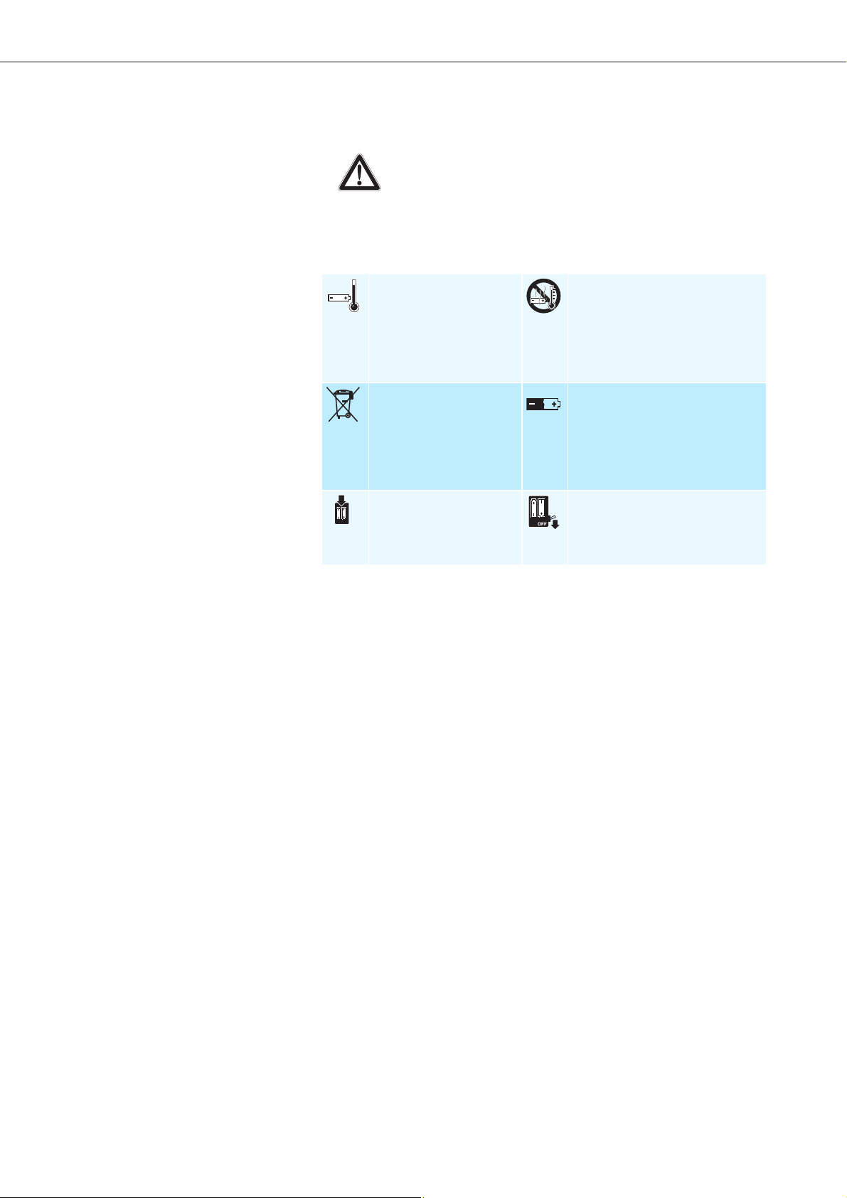
afety instructions for Lithium-Polymer rechargeable batteries
In extreme cases, abuse or misuse of
WARNING
•explosion,
•
fire development,
• heat generation or
•smoke/gas development.
rechargeable batteries can lead to:
Only charge
rechargeable
batteries at ambient
temperatures between
10°C/50°F and
40°C/104°F.
Dispose of defective
products with built-in
rechargeable batteries
at special collection
points or return them to
your specialist dealer.
Only use rechargeable
batteries recommended
by Sennheiser and the
appropriate chargers.
Do not heat above
70°C/158°F, e.g. do not
expose to sunlight or
throw into a fire.
When not using rechargeable
batteries for extended periods
of time, charge them regularly
(about every 3 months).
Switch battery pack-powered
products off after use.
3 | D 10 series
Page 5
Scope of delivery
A
&
B
D 10 HS
Quick
Guide
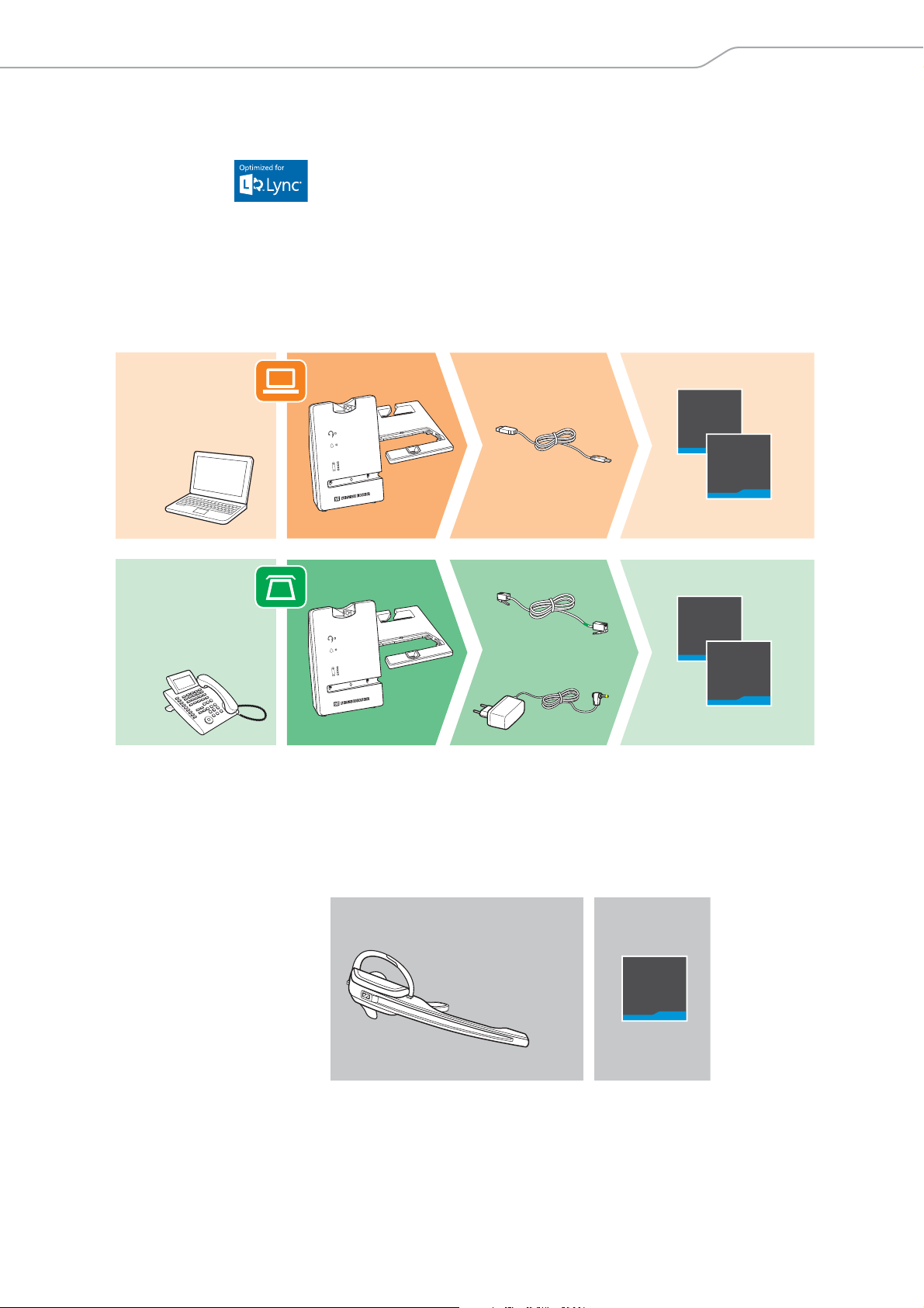
Scope of delivery
D 10 BS USB
D 10 BS USB ML
A
D 10 BS Phone
OR
The D 10 series base stations marked with ML in their name are optimized
for Microsoft
Base stations with components
D 10 BS USB for computer
D 10 BS USB ML for computer, optimized for Microsoft Lync
D 10 BS Phone for fixed line phone
Lync™.
USB
Phone
Safety
Guide
Quick
Guide
Safety
Guide
B
EU/UK/US/AU
The scope of delivery includes – depending on the product purchased –
a base station and/or a headset with corresponding components.
Headset with components
D 10 HS monaural, with different wearing styles
Quick
Guide
D 10 series | 4
Page 6
Product overview
쐋
Mic. Volume
Settings
Mode
0
3
6
9
1
A
B
C
2
3
4
5
6
Mic. Volume
Settings
Mode
0
3
6
9
1
A
B
C
2
3
4
5
6
Extra
Settings
D 10 Phone
DHSG
MSH
Short Range
Auto Link ON
Narrowband
Limiter
Fast
Link
1 2 3 4 5 6
1 2 3 4 5 6
Long Range
Auto Link OFF
Wideband
Standard
Handset
Lifter
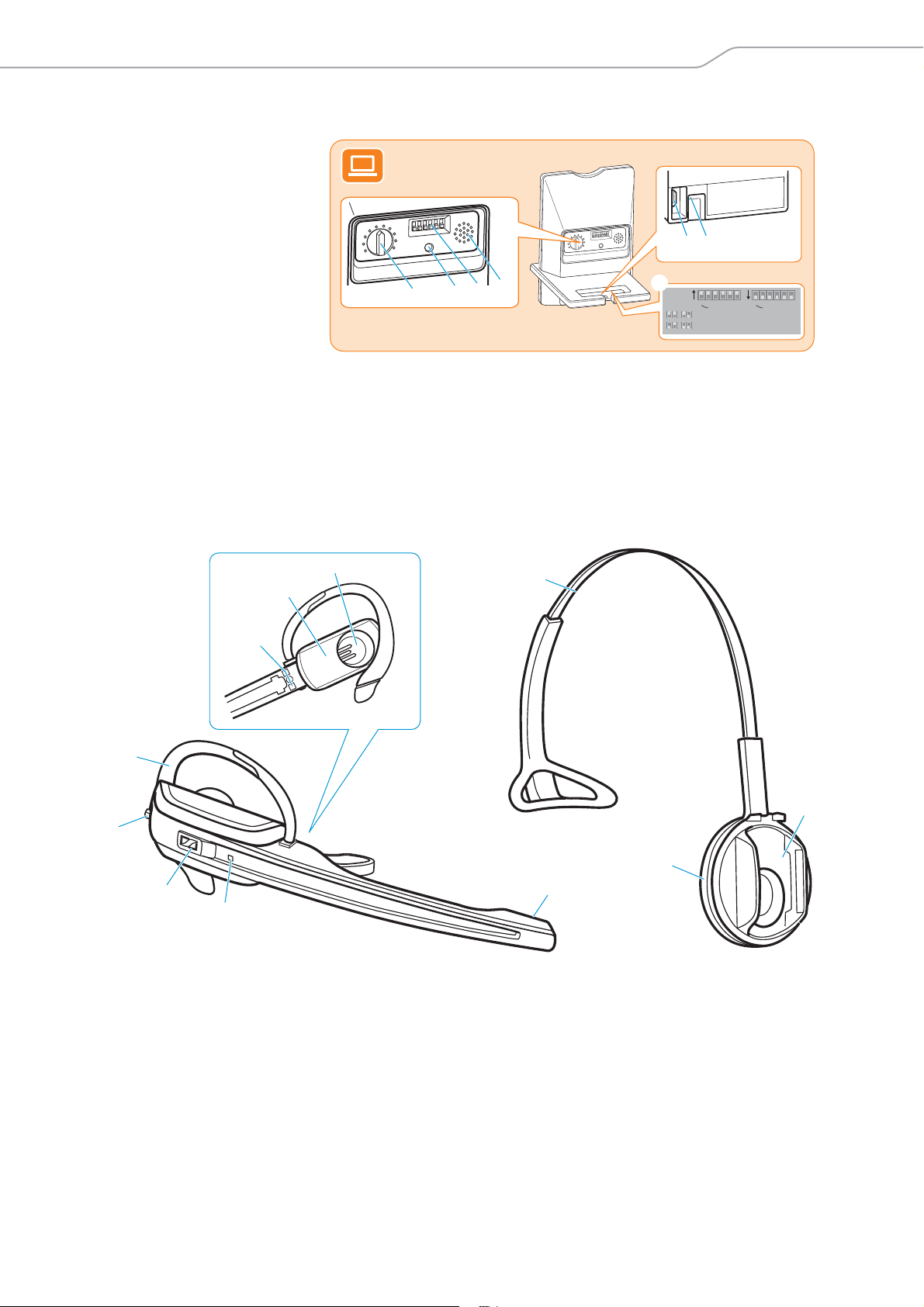
Product overview
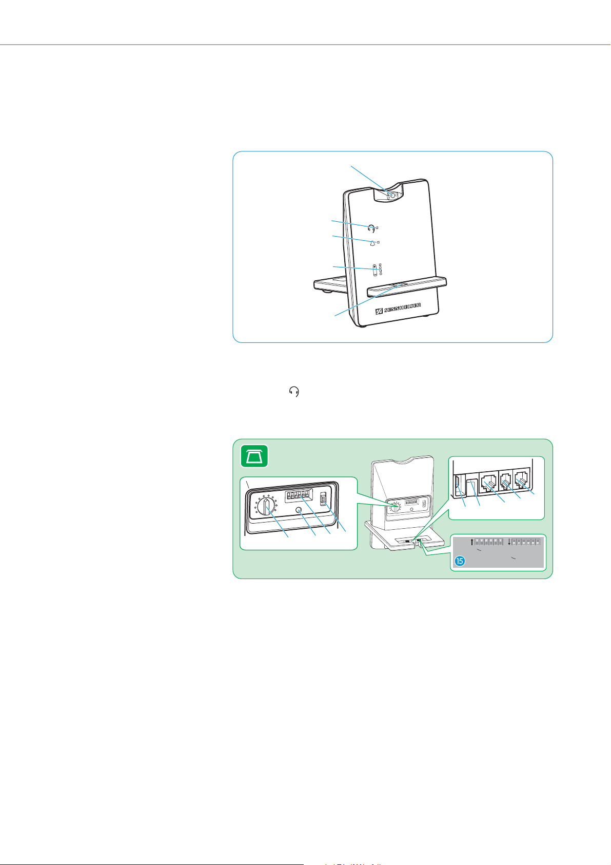
Product overview of the base station
Overview of the front
Magnetic holder with
charging
contacts
Link LED
Overview of the rear – Phone version
Microphone volume control
Set button
DIP switch row 1 to 6
ABC switch
Incoming call LED
Charge status LED
Headset holder
PC
socket (USB)
DC IN socket
Phone socket
Handset socket
ACC socket
Sticker for DIP switches
(located underneath the
headset holder)
5 | D 10 series
Page 7
Product overview
Ring Volume
Settings
0
3
6
9
1
2
3
4
5
6
Ring Volume
Settings
0
3
6
9
1
2
3
4
5
6
Extra
Settings
D 10 USB
Ringtone
Ringtone
OFF
1
2
3
Ringtone
Short Range
Auto Link ON
Narrowband
Limiter
1 2 3 4 5 61 2 3 4 5 6
Long Range
Auto Link OFF
Wideband
Standard
Overview of the rear – USB version
7
8
9
0
Ring tone volume control
Set button
DIP switch row 1 to 6
PC
DC IN socket
Sticker for DIP switches
Loudspeaker
Product overview of the headset
A
1
socket (USB)
(l
ocated underneath the
headset holder)
2
3
6
4
5
1 Headband
2 Headset holder
3 Ear pad
4 Microphone
5 Headset LED
7 Audio button: volume +/–, mute
8 Ear hook, adjustable
9 Charging contacts
0 Battery compartment
A Ear piece
6 Link button
D 10 series | 6
Page 8

Product overview
8
7
Overview of the buttons
Action Functions Page
왘 Press the
Link button 7
왘 Press and hold the
Link button 7 for
econds
5s
왘 Push the
Audio button 8
pwards/downwards
u
왘 Press the
Audio button 8
왘 Press and hold the Link
button 7 and the
dio button 8 for
Au
econds
5s
Establishes/disconnects the link
between headset and base station
Accepts/ends a call 23/25
Switches the headset on/off 32
Adjusts the ring tone volume and the
volume of the acoustic signals or the
audio volume
Mutes the microphone/unmutes the
microphone
Changes the direction of the volume
up/down function of the Audio
button 9
Special pairing mode (GAP) 33
23
21
22
21
7 | D 10 series
Page 9
Product overview
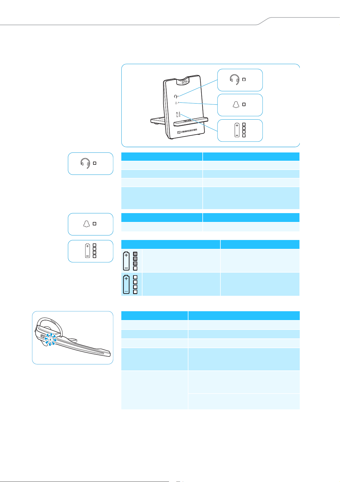
Overview of the LEDs
Overview of the LEDs of the base station
Link LED Meaning
lights up blue Active link to the headset
lights up red No link to the headset
flashes red Headset is muted
is off Standby mode, headset is within the
range of the base station, but no audio
link
Incoming call LED Meaning
flashes Incoming call
Charge status LED (white = lit) Meaning
LED segment 1 flashes
LED segments 1 – 4 are lit
Overview of the LEDs of the headset
Headset LED Meaning
lights up blue Headset is being charged in the base station
flashes blue slowly Active link to the base station
flashes red 3 times Rechargeable battery is almost flat
is off Standby mode or headset is switched off/
headset’s rechargeable battery is fully
charged
flashes blue/red Special pairing mode/direction of the volume
up/down function of the Audio button is
being changed
Pairing of an additional headset with the
base station/conference call
Rechargeable battery
is almost flat
Rechargeable battery
is charged
D 10 series | 8
Page 10
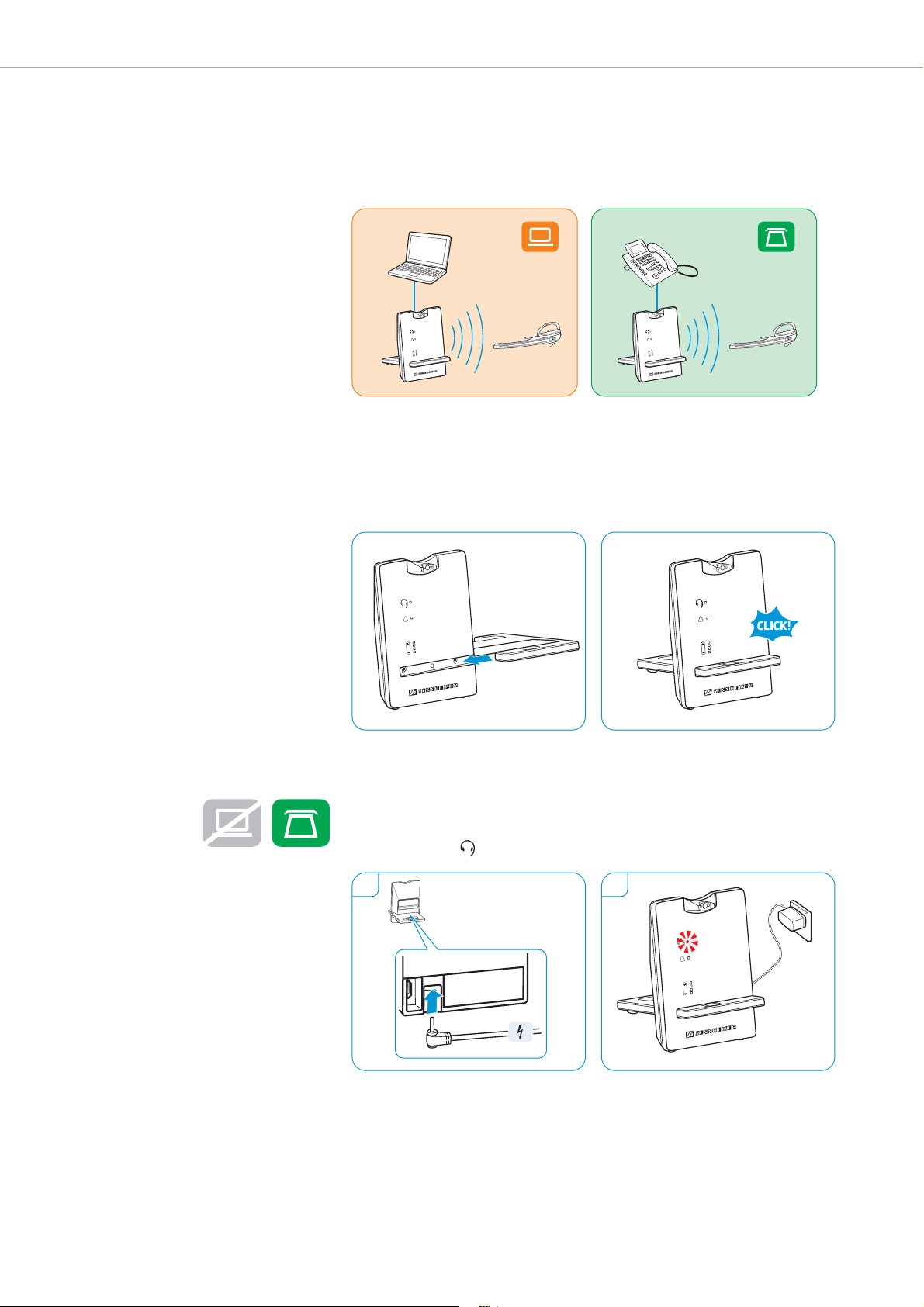
Setting up and connecting the base station
D 10 USB D 10 Phone
1 2
Setting up and connecting the
base station
Setting up the base station
왘 Insert the headset holder into the recess of the base station.
왘 Place the base station at a minimum distance
line phone.
of 15 cm from the fixed
Connecting the base station to the mains power supply
1 Connect the plug of the power supply unit to the DC IN socket (marked
yellow). Connect the power supply unit to a wall socket.
2 The Link LED lights up red.
Disconnecting the base station from the mains power supply
왘 If the product is not used for extended periods of time, unplug the
power supply unit
from the wall socket.
9 | D 10 series
Page 11
Setting up and connecting the base station
I
II
III
I
2
1
Mic. Volume
Settings
Mode
0
3
6
9
1
A
B
C
2
3
4
5
6
Mic. Volume
Settings
Mode
0
3
6
9
1
A
B
C
2
3
4
5
6
3
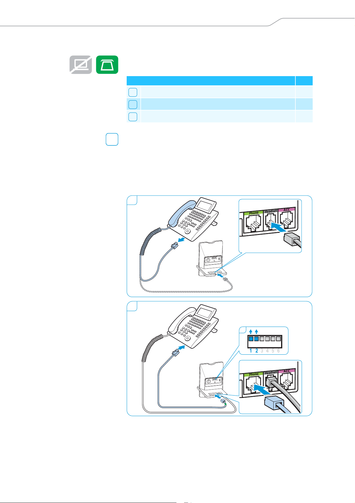
Connecting the base station to a fixed line phone
왘 Check which connection possibility is best suited for your telephone.
왘 Follow the instructions in the corresponding chapter.
Connection possibilities Page
Connection to a fixed line phone without headset socket 10
Connection to a fixed line phone with headset socket 11
Connection to an optional mechanical handset lifter 11
Connecting the base station to a fixed line phon
e without headset socket
1 Disconnect the handset cable from the telephone and connect it to the
Handset socket (marked gray) on the
base station.
2 Connect the telephone cable to the handset socket on the telephone
d to the Phone socket (marked green) on the base station.
an
3 Use a pointed object (e.g. a ball pen) to set the DIP switches 1 and 2 to
the posi
tion shown.
D 10 series | 10
Page 12
Setting up and connecting the base station
1
Mic. Volume
Settings
Mode
0
3
6
9
1
A
B
C
2
3
4
5
6
2
I
Mic. Volume
Settings
Mode
0
3
6
9
1
A
B
C
2
3
4
5
6
Co
II
nnecting the base station to a fixed line phone with headset socket
1 Connect the telephone cable to the he
and to the Phone socket (marked green) on the base station.
2 Use a pointed object (e.g. a ball pen) to set the DIP switches 1 and 2 to
the posi
adset socket on the telephone
tion shown.
III
Connecting the base station to an opti
The Sennheiser HSL 10 mechanical handset
onal mechanical handset lifter
lifter is an optional accessory
available from your Sennheiser partner. The handset lifter allows you to
answer calls even when you are away from your desk.
왘 Connect the base station to the fixed line phone as described in
r or .
chapte
왘 Connect the handset lifter to the ACC socket on the ba
II
se station.
왘 Connect the handset lifter to the fixed line phone. For more informa-
ion, refer to the instruction manual of the HSL 10 handset lifter.
t
11 | D 10 series
Page 13
Setting up and connecting the base station
1
2
Mic. Volume
Settings
Mode
0
3
6
9
1
A
B
C
2
3
4
5
6
1
2
Mic. Volume
Settings
Mode
0
3
6
9
1
A
B
C
2
3
4
5
6
Connecting the base station to an optional electronic hook switch control (EHS)
The necessary EHS connection cables as well as adapter cables for manufacturer specific standards are available as optional accessories from your
Sennheiser partner. The corresponding quick guides are supplied with
the cables or can be found on the product page on our website at
www.sennheiser.com/cco.
By way of example of a Siemens and an Alcatel adapter cable, the following
describes how to connect the base station to an electronic hook switch.
1 Connect the base station to the fixed line phone.
2 Use a pointed object (e.g. a ball pen) to set the DIP switch to the posi-
ti
Siemens, Agfeo, Aastra, Auerswald, etc.
on shown.
Alcatel
For an overview of the available connection and adapter cables, visit
the D 10 series product page on our website at
www.sennheiser.com/cco or contact your Sennheiser partner.
D 10 series | 12
Page 14

Setting up and connecting the base station
Ring Volume
Settings
0
3
6
9
1
2
3
4
5
6
Connecting the base station to a computer
왘 Connect the USB cable to the PC socket (marked orange) on the base
station and to a USB socket of your computer. The operating system
detects the USB audio device “Sennheiser D 10” and installs the necessary drivers.
Sennheiser PC software
The free Sennheiser PC software allows you to add value to your
Sennheiser products. The Sennheiser Updater, fo
updating of products with new software. For more information, visit our
website at www.sennheiser.com/cco/software.
r example, facilitates easy
Charging the headset before first use
Charge the rechargeable battery for at least 20 minutes without
interruption before using it for the first time. A complete charging process
takes about 60 minutes (see page 30).
During the first charging process, it may take up to 5 minutes until the
Headset LED lights up blue.
13 | D 10 series
Page 15

Individually adjusting the headset
1 2
3
4
Left
Right
Individually adjusting the headset
Using the headset with the ear hook
1 Insert the ear hook into the ear hook slot.
2 Pre-shape the ear hook by bending it slightly.
3 Place the ear hook around your ear.
4 Bend the flexible ear hook so that the headset sits comfortably and
securel
y on your ear.
D 10 series | 14
Page 16

Individually adjusting the headset
Using the headset with the headband
1 Remove the ear hook by carefully pulling it upwards.
2 Attach the headset to the headset holder of the headband.
3 Rotate the microphone boom and adjust the headset so that the ear
sts comfortably on your right or left ear.
pad re
1 2
3
Left
Right
15 | D 10 series
Page 17

Configuring the headset system
2
Configuring the headset system
Adjusting the headset system using the DIP switches
왘 Use a pointed object (e.g. a ball pen) to set the DIP switches to the
desired position.
Configuring the handset lifter/hook switch –
Switch position Function
Manual operation
Lifts/hangs up the handset manually or using
the handset lifter (Sennheiser HSL 10).
Electronic hook switch (DHSG standard)
Call control via the headset system.
For faster link establishment, see Fast Link.
Electronic hook switch (MSH standard)
Call control via the headset system.
Fast Link for DHSG standard and
HSL 10 handset lifter
Recommended for frequent callers. Shorter battery
life. Fast link establishment without delay due to
hidden link to the base station.
Adjusting the ring tones of the base station – DIP switches 1 and 2
Switch position Function
DIP switches 1 and 2
Ring tone is off.
Ring tone 1 is activated.
Ring tone 2 is activated.
Ring tone 3 is activated.
D 10 series | 16
Page 18

Configuring the headset system
Auto Link
A
djusting the radio range – DIP switch 3
If many DECT systems are operated in a
occur. In this case, you should change the radio range.
Switch position Function
Standard radio range
Reduced radio range
Use this setting in order to avoid interference with
other DECT systems
Range of approx. 10 m indoors
Automatically establishing the wireless link between headset and
base
station (Auto Link) – DIP switch 4
Switch position Function
Manual link establishment
When taking the headset out of the base station,
you have to manually establish the wireless link
between headset and base station.
Automatic link establishment – Auto Link
When taking the headset out of the base station, a
wireless link is automatically established between
headset and base station.
confined space, interference can
Switching between wideband and narrowband audio transmission –
DIP switch 5
Switch position Function
Wideband audio transmission
Automatic frequency adjustment of wideband and
narrowband calls. Wideband audio transmission is
e.g. supported by Skype and gives high speech
quality.
Battery life: 8 hours
Narrowband audio transmission
Battery life: 12 hours
Limiting the volume – DIP switch 6
Switch position Function
Standard limitation
Limited volume (country specific)
•AU version:
in compliance with Directive AS/ACIF G616:2006
• EU and US version:
in compliance with Directive 2003/10/EC
17 | D 10 series
Page 19

Configuring the headset system
Adjusting the audio signal by means of the dial tone
1 Put on the headset.
2 Press the Link button on the headset. The Link LED on the base
ation lights up blue.
st
3 Lift the handset. You hear a dial tone.
4 Set the ABC switch to the position A, B or C so that you can hear a clear
l tone in the headset.
dia
1 2
3 4
3
0
Mic. Volume
A
6
B
6
5
4
3
2
1
C
9
ode
M
Settings
D 10 series | 18
Page 20

Configuring the headset system
Adjusting the volume of the transmission
Adjusting the microphone volume of the call transmission
By default, the microphone volume cont
is suitable for most telephones.
왘 Make a call to someone who will help you find t
setting for your microphone.
왘 Turn the microphone volume control so that the other party can hear
u at a comfortable level.
yo
rol is set to position 4. This setting
he correct sensitivity
A
6
3
B
6
5
4
3
2
1
C
9
0
Mode
Settings
Mic. Volume
Adjusting the microphone volume of the USB transmission
Some softphones adjust the microphone sens
itivity automatically.
왘 Activate this function in order to be able to optimally use the
crophone and, via your operating system, adjust the microphone
mi
sensitivity so that the other party can hear you at a comfortable level
(see the Help function of your operating system).
Adjusting the volume of the ring tone
Adjusting the headset‘s ring tone volume and the volume of the acoustic
signals
&
왘 Make sure that the headset is in standby mode (the Link LED on the
base station is off).
If necessary, press the Link button on the headset.
왘 To adjust the volume, move the Audio button as shown in the diagram.
en the minimum or maximum volume is reached, you hear a double
Wh
beep in the headset.
Adjusting the ring tone volum
e of the base station
왘 Turn the volume control to reduce or increase the ring tone volume.
Ring Volume
19 | D 10 series
3
0
Ring Volume
6
6
5
4
3
2
1
9
gs
n
Setti
Page 21

Configuring the headset system
1
2
3
4
5
6
5s
Adjusting the automatic audio transmission “Auto Audio”
With the “Auto Audio” function activated and in the case of a USB
connection, the audio signals – e.g. from Windows
iTunes
– are automatically transmitted to the headset.
Media Player or
When you receive a call or when a connection to Skype™ or HeadSetup is
esta
blished, the audio transmission stops and you hear for example the
ring tone. The “Auto Audio” function is activated by default.
Deactivating the “Auto Audio” function
왘 Use a pointed object to press the Set button for approx. 5 seconds. The
nk LED rapidly flashes red several times.
Li
Activating the “Auto Audio” function
왘 Use a pointed object to press the Set button for approx. 5 seconds. The
nk LED rapidly flashes blue several times.
Li
D 10 series | 20
Page 22

Making calls using the headset
Making calls using the headset
Adjusting the volume
WARNING
Hearing damage due to high volumes!
Listening at high volume levels for long periods can lead to
permanent hearing defects.
왘 Set the volume to a low level b
왘 Do not continuously expose yourself to high volumes.
Adjusting the volume of the audio signal
You can adjust the volume of the audio signal by means of the dial tone or
dur
ing a call.
왘 Make sure that a link is established between headset and base station
e Link LED on the base station lights up blue). If necessary, press
(th
the Link button on the headset.
왘 To adjust the volume, move the Audio button as shown in the diagram.
en the minimum or maximum volume is reached, you hear a double
Wh
beep in the headset.
efore putting on the headset.
Swapping the direction of the volume buttons
왘 On the Audio button, check which direction is assigned “volume down”.
왘 Simultaneously press and hold the Lin
for 5 seconds.
The Headset LED alternately flashes blue/red.
왘 Push the Audio button in the direction “volume down” until the
adset LED goes off. The direction of the volume up/down function of
He
the Audio button is changed. The headset switches to standby mode.
5 s 5 s
k button and the Audio button
21 | D 10 series
Page 23

Making calls using the headset
55 m
Muting the headset’s microphone
왘 Press the Audio button.
The microphone is muted. While the microphone is muted, the
Link LED on the base station flashes red.
Unmuting the headset’s microphone
왘 Press the Audio button.
ou hear a beep in the headset. The muting is canceled and the
Y
Link LED on the base station lights up blue.
If you leave the DECT range
In normal office buildings, the range between headset and base station is
up to 55 m. If, during a call, the audio quality deteriorates or the link breaks
down completely, you hear a descending sequence of beeps in the headset.
The Link LED on the base station lights up red.
왘 Re-enter the DECT range of the ba
You hear a ring tone in the headset.
왘 Press the Link button on the headset to resume the call.
f your softphone supports call control, the call will automatically be
I
ended 60 seconds after leaving the DECT range.
se station within 60 seconds.
D 10 series | 22
Page 24

Making calls using the headset
disconnectedconnected disconnectedconnected
Calling via the fixed line phone using the headset
Establishing/disconnecting a wireless link
If you want to use the headset to accept, make or end calls, you have to
es
tablish a wireless link between headset and base station. You can choose
between manual and automatic link establishment (see “Auto Link” on
page 17).
왘 Press the Link button on the headset.
The link is established. The Link LED on the base station lights up
–
blue and the Headset LED flashes blue slowly.
OR
– The link is disconnected. The Link LED on the base station and the
dset LED go off. The headset is in standby mode.
Hea
If your telephone has a built-in electronic hook switch supporting
the MSH standard, you can only disconnect the wireless link between
headset and base station by placing the headset into the base
station.
Managing calls without using a call control f
Accepting a call: Y
Link button on the headset. Lift the handset or press the “accept call”
button on your fixed line phone.
Making a call: Press the Link button on the headset to establish a link
between base station and headset. Lift the handset and dial the desired
number. The phone connection is established.
ou hear the ring tone of the fixed line phone. Press the
unctionality
Ending a call: Hang up the handset or press the “end call” button on your
fixed line phone.
23 | D 10 series
Page 25

Making calls using the headset
Managing calls using a call control functionality (EHS, HSL 10)
Accepting a call: Y
on the headset to accept the call. The handset lifter/electronic hook switch
lifts the handset.
Making a call: Dial the desired number. Press the Link button on the
headset to establish a link between base station and headset. The phone
connection is established automatically.
Ending a call: Press the Link button. If the other party hangs up, your
telephone and your headset become automatically ready to receive the
next call.
ou hear a ring tone in the headset. Press the Link button
Frequent callers who use an electronic hook switch with DHSG capability
are recommended to activate the “Fast Link” function for faster link
establishment (see page 15)
Switch position Function
Fast Link (only when DHSG standard is used)
Recommended for frequent callers. Shorter battery
life. Fast link establishment without delay due to
hidden link to the base station.
Switching a call between headset and fixed line phone
왘 Press the Link button on the headset to switch between headset and
ndset of the fixed line phone during an ongoing call.
ha
In case of a fixed line phone with a handset lifter/an electronic hook
switch, this switching can only be done on the fixed line phone.
D 10 series | 24
Page 26

Making calls using the headset
disconnectedconnected disconnectedconnected
Calling via the computer using the headset
Establishing/disconnecting a wireless link
If you want to use the headset to accept, make or end calls, you have to
es
tablish a wireless link between headset and base station. You can choose
between manual and automatic link establishment (see “Auto Link” on
page 17).
왘 Press the Link button on the headset.
The link is established. The Link LED on the base station lights up
–
blue and the Headset LED flashes blue slowly.
OR
– The link is disconnected. The Link LED on the base station and the
dset LED go off. The headset is in standby mode.
Hea
Managing calls via the softphone
Accepting a call:
hear a ring tone in the headset. Click on “Accept call” on your softphone.
Making a call: Press the Link button on the headset to establish a link
between base station and headset. If the “Auto Audio” function is
activated, this step is not necessary (see page 20). Start the call using your
softphone.
Ending a call: End the call using your softphone.
The softphone signals that you are receiving a call. You
25 | D 10 series
Page 27

Making calls using the headset
Managing calls via the headset
The Microsoft
Lync™ softphone supports this function automatically. If
you use another softphone, please visit our website at
www.sennheiser.com and check whether and which free Sennheiser
software you additionally require. If necessary, install the software in order
to manage calls directly via the headset.
Accepting a call: The softphone signals that you are receiving a call. You
hear a ring tone in the headset. Press the Link button on the headset to
accept the call.
Making a call: Start the call using your softphone, the audio signal is
automatically transmitted to the headset.
Ending a call: Press the Link button. If the other party hangs up, your
softphone and your headset become automatically ready to receive the
next call.
D 10 series | 26
Page 28

Making calls using the headset
MASTER
GUEST 1
GUEST 3
GUEST 2
New MASTER
3x
or
Making a conference call
The headset system allows you to make a conference call with up to
4 D 10 series headsets. The first headset paired (master) is used control
the call establishment and end of conversation.
Pairing the master headset with the base station
The Link LED on the base station is off
lights up red (no headset paired).
왘 Place the master headset into the base station.
The Hea
dset LED alternately flashes blue/red until a link to the base
station is established. The Headset LED flashes blue 3 times.
왘 Take the headset out of the base station and press the Link button to
r the headset with the base station.
pai
The Link LED on the base station lights up blue.
(headset is disconnected) or
27 | D 10 series
Page 29

Making calls using the headset
3x
Press & hold
the mute button...
Accept the
Guest headset.
... & insert the headset
into the charging
cradle.
MASTER
GUEST 1-3
Adding a guest headset to a
conference call
The Link LED on the base station lights up blue.
왘 Press and hold the Audio button while p
lacing the guest headset into
the base station of the master headset.
The Headset LED alternately flashes blue/red until a link to the base
station is established. The Headset LED flashes blue 3 times.
왘 Take the guest headset out of the base station. You hear a beep in the
ter headset.
mas
왘 To add the guest headset to the conference call, press the Link button
o
n the master headset within 15 seconds.
왘 Repeat this procedure to add additional guest headsets to the
onference call.
c
왘 Call the other party.
The Link
LED on the base station flashes blue.
D 10 series | 28
Page 30

Making calls using the headset
3x on
Easy paring
Dropping
왘 Press the Link button on the guest headset.
a guest headset from the conference call
The guest headset is
dropped from the conference call.
“easy pairing”
To subsequently use the guest headset with other base stations,
place the guest
headsets into the other base stations. The
Headset LED alternately flashes blue/red until a link is established.
Ending a conference call
왘 Place the master headset into the magnetic holder of the base station
end the conference call and to drop the guest headsets from the
to
conference call.
29 | D 10 series
Page 31

Charging the headset and storing the headset system
Charging the headset and storing
the headset system
Charging the headset
Always store the headset in the base station to ensure that it is fully
charged when needed. The intelligent battery charging technology
prevents over-charging.
왘 Place the headset into the magnetic hol
The Headset LED lights up blue and the rechargeable battery is being
charged. The Charge status LED on the base station indicates the
charge status:
LED segment
(white = lit up)
Shortly before the rechargeable battery is about to run flat, only one
LED segment lights up weakly. The Headset LED flashes red and you hear
three beeps. You have several minutes of battery reserve. When the
rechargeable battery is flat, the headset switches off.
Required
charging time
approx.
10 min.
approx.
20 min.
approx.
40 min.
approx.
60 min.
der of the base station.
Corresponds to a talk time of
Wideband Narrowband
approx. 2 hrs approx. 3 hrs
approx. 4 hrs approx. 6 hrs
approx. 6 hrs approx. 9 hrs
approx. 8 hrs approx. 12 hrs
f the headset is outside the range of the base station, it will switch
off after 30 minutes in order to conserve battery power.
D 10 series | 30
Page 32

Charging the headset and storing the headset system
MCH 7
CH 10 USB
C
harging the headset using the optional CH 10 headset charger
The CH 10 headset charger is an opti
Sennheiser partner. The CH 10 allows you to charge additional D 10 series
headsets, e.g. for sharing the same base station when working shifts.
onal accessory available from your
왘 Refer to the instruction manual of the CH 10 for more information.
Charging several headsets simultaneously
The MCH 7 multi USB power source is an optional
accessory available from
your Sennheiser partner. Together with the CH 10 USB, the MCH 7 allows
you to charge up to 7 headsets simultaneously.
왘 Refer to the instruction manual of the
MCH 7 for more information.
31 | D 10 series
Page 33

Charging the headset and storing the headset system
1
2
5 s
3x
0
3
6
9
1
2
3
4
5
6
Switching the headset system off during extended non-use
You can switch off the headset system (1) or the headset (2) when not
using the products for extended periods of time (e.g. when you are on
holiday).
Switching the headset system off
1 Disconnect the base station from the mains power s
upply. The base
station switches off immediately, the headset switches off about
30 minutes later.
2 Press and hold the Link button for 5 seconds to switch off the headset
ediately. The Headset LED flashes red 3 times, the headset is
imm
switched off completely.
The Link LED on the base station lights up red after a short time, the
Charge status LED on the base station goes off.
Switching the headset system on and pairing the components
왘 Plug the power supply unit into a wall socket. The base station is
switched on.
왘 Place the headset into the magnetic holder o
f the base station. The
Headset LED flashes blue 3 times and then lights up blue. The base
station and the headset are paired.
D 10 series | 32
Page 34

Sharing a workplace
3x
5 s
Sharing a workplace
The headsets and base stations of the D 10 series are compatible with each
other. If, for example, you share a workplace, you can use one base station
with different headsets. The last headset paired with the base station can
be used without more ado.
왘 Place the headset to be used into the m
station.
The Headset LED alternately flashes blue/red until the headset is
successfully paired with the base station. The Headset LED flashes
3 times blue and then goes off. You can now use the newly paired
headset.
If pairing has failed, the Link LED on the base station lights up red or is
off. Repeat the procedure.
agnetic holder of the base
Using the headset with a third party base station
(DECT-GAP telephone)
왘 Place the headset at a maximum distance of 1 m from the third party
base station.
왘 Simultaneously press and hold the headset’s Link
Audio button for 5 seconds.
The headset switches to a special pairing mode and the Headset LED
alternately flashes blue/red.
왘 Set the third party base station to a special pairing mode (see the
nstruction manual of the third party base station). The default code
i
for the headset is “0000”.
The headset
successful, the Headset LED goes off.
If pairing is not successful within 60
to standby mode.
To pair the headset again with a D 10 series base station:
왘 Simultaneously press and hold the headset’s Link
Audio button for 5 seconds.
The headset switches to a special pairing mode and the Headset LED
alternately flashes blue/red.
왘 Place the headset into the magnetic ho
Headset LED flashes blue 3 times and then lights up blue. The base
station and the headset are paired.
pairs with the third party base station. If pairing is
seconds, the headset switches back
lder of the base station. The
button and
button and
33 | D 10 series
Page 35

Cleaning and maintaining the headset system
Cleaning and maintaining the
headset system
CAUTION
Liquids can damage the electronics of the product!
Liquids entering the housing of the product can short-circuit the
electronics.
왘 Keep all liquids far away from the product.
왘 Do not use any solvents
왘 Before cleaning, disconnect the base station from the mains power
supply.
or cleansing agents.
왘 Only use a dry and soft cloth
왘 Clean the charging contacts of the base station and the charging
tacts of the headset from time to time using e.g. a cotton swab.
con
to clean the product.
D 10 series | 34
Page 36

Cleaning and maintaining the headset system
A
B
Replacing the ear pads
For reasons of hygiene, you should replace the ear pads from time to time.
Spare ear pads are available from your Sennheiser partner.
1 Carefully remove the old ear pad from the ea
fastening ring of the old ear pad is also removed from the ear cup.
2 Pull the collar B of the ear pad over the notch A of the headband.
3 Turn the ear pad counter-clockwise over the notch until the collar
com
r cup. Make sure that the
pletely surrounds the ear cup.
1
3
2
35 | D 10 series
Page 37

Cleaning and maintaining the headset system
2 3
4
Replacing the headset’s rechargeable battery
CAUTION
Damage to the product due to improper handling
The cables can be kinked or damaged if you open the battery compartment
too jerkily.
왘 Carefully open the battery compartment and loosen the connector plug
the rechargeable battery.
of
Spare rechargeable batteries are available from your Sennheiser partner.
Only use spare rechargeable batteries recommended by Sennheiser.
1 Remove the ear hook or the headband (see page 14) and open the
battery com
1
partment.
2 Carefully move the battery compartment cover in the direction of the
arr
ow until you overcome a slight resistance. Remove the rechargeable
battery and carefully loosen the connector plug of it.
3 Insert the connector plug of the new rechargeable battery into the
onnection socket. Observe correct orientation of the connector plug.
c
4 Close the battery compartment.
D 10 series | 36
Page 38

If a problem occurs
If a problem occurs
Problem Possible cause Possible solution Page
The headset is placed into
the base station but the
Charge status LED is off
Link between headset
and base station cannot
be established
Bad radio link between
headset and base station
Noise interference and
connection loss
The rechargeable battery
cannot be charged
The rechargeable battery is
quickly depleted even after
charging
Bad audio quality, the other
party sounds too low or too
loud
The sound from the fixed line
phone is distorted and
disturbed
Base station is not connected
to the mains power supply
Rechargeable battery is deep
discharged
Headset is not paired with
the base station, the Link
LED lights up red
Base station is only
connected via the USB cable
Transmission range is
exceeded
Microphone rubs on the cheek
or perhaps the beard
Too many DECT systems
within the radio range
Distance between base
station and fixed line phone
is so small that interference
occurs
Charging contacts of the
headset or the base station
are dirty
Rechargeable battery is
defective
Headset is not properly
placed into the magnetic
holder of the base station
Overaged rechargeable
battery
Microphone sensitivity is not
correctly adjusted
Base station is not adjusted
to the fixed line phone.
Connect the base station to the
mains power supply.
Wait several minutes until the
Charge status LED lights up.
For quick-charging the headset:
Briefly press the Set button at
the rear of the base station.
Place the headset into the base
station.
Connect the base station to the
mains power supply.
Reduce the distance between
headset and base station.
Adjust the radio range. 17
Bend the microphone boom so
that the microphone is about
0.8 - 1.2” (2 - 3 cm) from the
corner of your mouth.
Reduce the radio range. 17
Set the base station to
narrowband transmission.
Increase the distance between
base station and fixed line
phone.
Clean the charging contacts on
the headset and on the base
station.
Replace the defective
rechargeable battery with a new
one.
Check if the headset is properly
placed into the magnetic holder.
Replace the overaged
rechargeable battery with a new
one.
Adjust the microphone
sensitivity.
Use the ABC switch to adjust the
base station to your fixed line
phone.
30
23
14
17
34
36
30
36
19
19
9
5
9
–
–
For more information and an FAQ list, please visit our website at www.sennheiser.com.
If a problem occurs that is not listed in the above table or if the problem cannot be solved with the proposed
solutions, please contact your local Sennheiser partner for assistance.
To find a Sennheiser partner in your country, search at www.sennheiser.com under “Service & Support”.
37 | D 10 series
Page 39

Specifications
Specifications
Base station
D 10 BS USB/D 10 BS USB ML/D 10 BS Phone
Dimensions 88 x 119 x 100 mm (W x H x D)
Weight
D 10 BS Phone
D 10 BS USB
Operating temperature range +5 °C to +45 °C (+41 °F to +113 °F)
Storage temperature range –20 °C to +70 °C (–4 °F to +158 °F)
Headset
D 10 HS
Dimensions 140 x 24 x 22 mm (W x H x D)
Weight with ear hook: approx. 22 g
Talk time narrowband: up to 12 hours
Charging time 50%: approx. 20 min
Range
(environment dependent)
Rechargeable battery
(built-in)
Output power EU/AUS: 24 dbm/250 mW
Speaker type dynamic, neodymium magnet
Microphone type electret microphone, noise canceling
Operating temperature range +5 °C to +45 °C (+41°F to +113 °F)
Storage temperature range –20 °C to +70 °C (–4 °F to +158 °F)
approx. 352 g
approx. 328 g
with headband: approx. 45 g
wideband: up to 8 hours
100%: approx. 1 hour
free line of sight: up to 180 m
in office buildings: up to 55 m
Lithium Polymer
3.7 V; 215 mAh
U
SA/CAN: 20.4 dbm/100 mW
Power supply unit – PSAA05E/K/S/A
Nominal input voltage 100 – 240 V~
Nominal input current max. 0.2 A
Mains frequency 50 – 60 Hz
Nominal output voltage 5.9 V
Nominal output current max. 850 mA
Operating temperature range +5 °C to +45 °C (+41 °F to +113 °F)
Storage temperature range –20 °C to +70 °C (–4 °F to +158 °F)
Relative humidity operation: 20 to 85%
storage: 20 to 95%
Weight approx. 75 g
D 10 series | 38
Page 40

Specifications
DECT
EU, UK, AU:
CAT IQ 1.0
Frequency 1880 to 1900 MHz 1920 to 1930 MHz
SAR value of D 10 HS Ear hook:
0.029W/kg
Headband:
0.050 W/kg
In compliance with
urope: EMC EN 301489-6
E
Radio EN 301406
Safety EN 60950-1
SAR EN 50360 ref EN
USA & Canada:
This product
meets the safety requirements of CSA No. 231437
US version:
DECT 6.0
0.048W/kg
62209-1 (headset)
Canada: IC: 2099A-D10BSPHONE
(D10 BS Phone-US, D10 BS USB-US,
D10 BS USB ML-US)
IC: 2099A-D10HS (D 10 HS)
USA: FCC ID: DMOCBDDGG (D10 BS Phone-US,
D10 BS USB-US, D10 BS USB ML-US)
FCC ID: DMOCDHDGG (D 10 HS)
39 | D 10 series
Page 41

Manufacturer Declarations
1321
Manufacturer Declarations
Warranty
Sennheiser Communications A/S gives a warranty of 24 months on this
pr
oduct. For the current warranty conditions, please visit our website at
www.sennheiser.com or contact your Sennheiser partner.
In compliance with the following requirements
• WEEE Directive (2012/19/EU)
se dispose of this product by taking it to your local collection point
Plea
or recycling center for such equipment. This will help to protect the
environment in which we all live.
• Battery Directive (2013/56/EU)
The product’s built-in rechargeable batteries can be recycled. In order
to protect the environment, please dispose of defective products with
their rechargeable batteries as special waste or return them to your
specialist dealer.
CE Conformity
• R&TTE Directive (1999/5/EC)
EMC Directive (2014/30/EU)
•
• Low Voltage Directive (2006/95/EC)
• ErP Directive (2009/125/EC)
• RoHS Directive (2011/65/EU)
The declaration is available at www.sennheiser.com.
Before putting the product into operation, please observe the respective
country-specific regulations!
D 10 series | 40
Page 42

Manufacturer Declarations
St
atement regarding FCC
FCC Declaration of Conformity (DoC)
SENNHEISER
Model No:
Sennheiser Electronic Corporation
We,
One Enterprise Drive • Old Lyme •
CT 06371 • USA
Tel: +1 (860) 434 9190, ext. 144
Fax: +1 (860) 434 1759
declare the above device comply with the requirements of Federal Communicat ions Comm iss ion.
This device compli es with P art 15 of the FCC rules . Operation is subjected t o the following two conditions:
1) This device may not cause harmful i nterference, and
2) This device must accept any int erference received, including interference that may cause undes ired operation.
Resp ons ible Party : Greg Beebe
D 10 BS Phone-US, D 10 BS USB-US,
D 10 BS USB ML-US
This equipment has been tested and found to comply with the limits for a Class
B digital device of the FCC Rules, pursuant to part 15 of the FCC Rules. These
limits are designed to provide reasonable protection against harmful
interference in a residential installation.
This equipment generates, uses and can radiate radio frequency energy and, if
not installed and used in accordance with the instructions, may cause harmful
interference to radio communications. However, there is no guarantee that
interference will not occur in a particular installation. If this equipment does
cause harmful interference to radio or television reception, which can be
determined by turning the equipment off and on, the user is encouraged to try
to correct the interference by one or more of the following measures:
• Reorient or relocate the receiving antenna.
• Increase the separation between the equipment and receiver.
• Connect the equipment into an outlet on a circuit different from that to
which the receiver is connected.
• Consult the dealer or an experienced radio/TV technician for help.
Changes or modifications made to this equipment not expressly approved by
Sennheiser electronic Corp. may void the FCC authorization to operate this
equipment.
The headset D10HS complies with FC C RF radiation exposure limits for devices
used by the general public. It has been tested for SAR and has complied with
Industry Canada SAR limits for devices used by the general public.
41 | D 10 series
Statement regarding Industry Canada
This device complies with RSS-213 Issue 2 of the Industry Canada Rules.
Operation is subject to the following two conditions: (1) This device may not
cause harmful interference, and (2) this device must accept any interference
received, including interference that may cause undesired operation.
The headset D10HS complies with Industry Canada RF radiation exposure
limits for devices used by the general public. It has been tested for SAR and has
complied with Industry Canada SAR limits for devices used by the general
public.
Trademarks
Sennheiser is a registered trademark of Sennheiser electronic GmbH & Co. KG.
Other product and company names mentioned in this instruction manual may
be the trademarks or registered trademarks of their respective owners.
Page 43

Sennheiser Communications A/S
Industriparken 27, DK-2750 Ballerup, Denmark
www.sennheiser.com
Publ. 11/14, A01
 Loading...