

Page 1

AUDIO
DISTRIBUTION
NETWORK
SENNHEISER ADN
Instruction manual
Page 2

Contents
Contents
Important safety instructions ........................................................................................ 3
The Sennheiser ADN conference system ...................................................................... 5
Available system components – scope of delivery .................................................... 6
Overview of the components .......................................................................................... 7
ADN D1 delegate unit .................................................................................................... 8
ADN C1 chairman unit ................................................................................................... 9
ADN CU1 central unit ................................................................................................... 10
Overview of the ADN CU1 display panel .................................................................. 11
The “Conference Manager” software ....................................................................... 12
The SDC CBL RJ-45 system cables ............................................................................. 12
Structuring and controlling the conference system ................................................ 13
Putting the conference system into operation ......................................................... 15
Preparing the central unit for use ............................................................................. 15
Preparing the conference units for use .................................................................... 16
Setting up the conference system ............................................................................ 17
Switching the conference system on/off ................................................................ 20
Using the central unit ..................................................................................................... 21
Deactivating the lock mode of the central unit ...................................................... 21
Functions of the keys .................................................................................................. 21
Configuring the conference system via the central unit ........................................ 22
Overview of the operating menu .............................................................................. 22
Working with the operating menu ........................................................................... 25
Adjusting the conference settings – “Conference” ............................................... 26
Adjusting the audio settings – “Audio” .................................................................. 31
Checking the system and detecting problems – “System” ................................. 34
Adjusting the language – “Language” .................................................................... 41
Adjusting further settings – “Settings” .................................................................. 42
Running a conference ..................................................................................................... 44
Operating a delegate unit ........................................................................................... 45
Operating a chairman unit .......................................................................................... 46
Setting the volume of the conference units’ built-in loudspeakers ................... 48
Adding conference units to the conference system during operation .............. 48
Using the “Conference Manager” software ............................................................... 49
Possibilities of usage of the software and the conference system .................... 49
Preparing the central unit’s integrated software for use .................................... 50
Preparing the Windows version of the software for use ..................................... 50
Starting/exiting the software .................................................................................... 55
Getting to know and adjusting the basic features of the software ................... 56
Using the conference system and the software .................................................... 66
Preparing a conference and mapping a conference room –
“Setup” operating mode ............................................................................................. 72
Initializing the conference units – “Setup” operating mode ............................... 86
Adjusting the conference settings – “Setup” operating mode ........................... 90
Controlling and monitoring a conference – “Live” operating mode .................. 95
Using the log and diagnosis function – “Event Log“ .......................................... 102
1
Page 3

Contents
Cleaning and maintaining the conference system ................................................ 104
Updating the firmware of the conference system ................................................ 105
If a problem occurs ... ................................................................................................... 106
Accessories ..................................................................................................................... 108
Specifications ................................................................................................................. 109
Appendix ......................................................................................................................... 111
Manufacturer Declarations ......................................................................................... 116
2
Page 4

Important safety instructions
Important safety instructions
1. Read these instructions.
2. Keep these instructions. Always include these instructions when passing the
pparatus on to third parties.
a
3. Heed all warnings.
4. Follow all instructions.
5. Do not use this apparatus near water.
6. Clean only with a dry cloth.
7. Do not block any ventilation openings. Install in accordance with the manu-
facturer’s instructions.
8. Do not install near any heat sources such
other apparatus (including amplifiers) that produce heat.
9. Do not defeat the safety purpose of
A polarized plug has two blades with one wider than the other. A grounding
type plug has two blades and a third grounding prong. The wide blade or the
third prong are provided for your safety. If the provided plug does not fit into
your outlet, consult an electrician for replacement of the obsolete outlet.
10. Protect the power cord from being walked on or pinched, particularly at plugs,
o
nvenience receptacles, and the point where they exit from the apparatus.
c
11. Only use attachments/accessories specif
12. Use only with the cart, stand, tripod, bracket, or table specified by the m
facturer, or sold with the apparatus.
When a cart is used, use caution when moving the cart/apparatus combination
to avoid injury from tip-over.
13. Unplug this apparatus during lightning storms or when unused for long periods
of time.
14. Refer all servicing to qualified service personnel.
Servicing is required when the apparatus has b
as power supply cord or plug is damaged, liquid has been spilled or objects have
fallen into the apparatus, when the apparatus has been exposed to rain or
moisture, does not operate normally, or has been dropped.
15. To completely disconnect this apparatus from the
power supply cord plug from the AC receptacle.
16. WARNING: To reduce the risk of fire or electric shock,
ratus to rain or moisture.
m
17. Do not expose this equip
objects filled with liquids, such as vases, are placed on the equipment.
18. The mains plug of the power supply cord shall remain readily operable.
ent to dripping or splashing and ensure that no
as radiators, heat registers, stoves, or
the p
olarized or grounding-type plug.
ied by the manufacturer.
een damage
d in any way, such
AC ma
ins, disconnect the
do not expose this appa-
anu-
3
Page 5

Important safety instructions
Hazard warnings on the rear of the central unit
The label shown on the left is attached to the rear of the central unit. The symbols
on this label have the following meaning:
This symbol is intended to alert the user to the presence of uninsulated dangerous
voltage within the central unit’s enclosure that may be of sufficient magnitude to
constitute risk of fire or electric shock.
This symbol is intended to alert the user to the risk of electric shock if the central
unit is opened. There are no user serviceable parts inside. Refer servicing to qualified personnel only.
This symbol is intended to alert the user to the presence of important operating
and maintenance instructions in the literature accompanying this product.
Overloading
Do not overload wall outlets and extension cords as this
tric shock.
Safety check
Upon completion of any service or repairs to
to perform safety checks to determine that the device is in safe operating order.
Danger of hearing damage due to high volumes
When the conference participants listen to the floor channel via headphones, they
can adjust the volume themselves. In doing so, sound pressure exceeding 85 dB(A)
can be produced. 85 dB(A) is the sound pressure corresponding to the maximum
permissible volume which is by law (in some countries) allowed to affect your
hearing for the duration of a working day. It is used as a basis according to the
specifications of industrial medicine. Higher volumes or longer durations can
damage your hearing. At higher volumes, the duration must be shortened in order
to prevent hearing damage. The following are sure signs that you have been
subjected to excessive noise for too long a time:
in
• You can hear ringing or whistl
• You have the impression (even for a short time only) that you can no longer
hear high notes.
Inform the conference participants about these facts and, if
set the volume to a medium level.
g sounds in your ears.
this device, ask the service technician
may result in fire and elec-
necessary, ask them to
Intended use
Intended use of the products in
• having read this instruction manual, especial
instructions”,
• using the products within the operating conditions and limitations described in
this instruction manual.
“Improper use” means using the products other than as
tion manual, or under operating conditions which differ from those described
herein.
4
cludes:
ly the chapter “Important safety
described in this instruc-
Page 6

The Sennheiser ADN conference system
The Sennheiser ADN conference system
Sennheiser ADN stands for Sennheiser Audio Distribution Network – the new
generation of digital conference equipment:
• Ideal for small to medium size conferences with approx. 30 participants
• High-quality audio signal due quality micropho
• Attractive design – fits into modern or tradi
• Guaranteed operational reliability due to state-of-the-art
nology
• Can be adapted quickly and easily to different room sizes and participant
numbers
• Intuitive configuration and control of the conference system via the operating
menu or the integrated software package
ne and built-in loudspeakers
tional style conference rooms
transmission tech-
5
Page 7

Available system components – scope of delivery
Available system components –
scope of delivery
The following ADN system components are available:
Central unit (Cat. No.: 502757) 1 ADN CU1 central unit
1 quick guide
1 CD ROM (including, among other things, the “Conference Manager”
so
ftware (Windows) and the instruction manual for the overal
system as PDF)
Mains cable for central unit available in EU, UK and US versions, length 1.8 m (see “Accessories” on page 108)
Delegate unit (Cat. No.: 502758) 1 ADN D1 delegate unit
1 quick guide
Chairman unit (Cat. No.: 502759) 1 ADN C1 chairman unit
1 quick guide
System cable SDC CBL RJ-45, available in differ
l conference
ent lengths (see “Accessories” on page 108)
6
Page 8
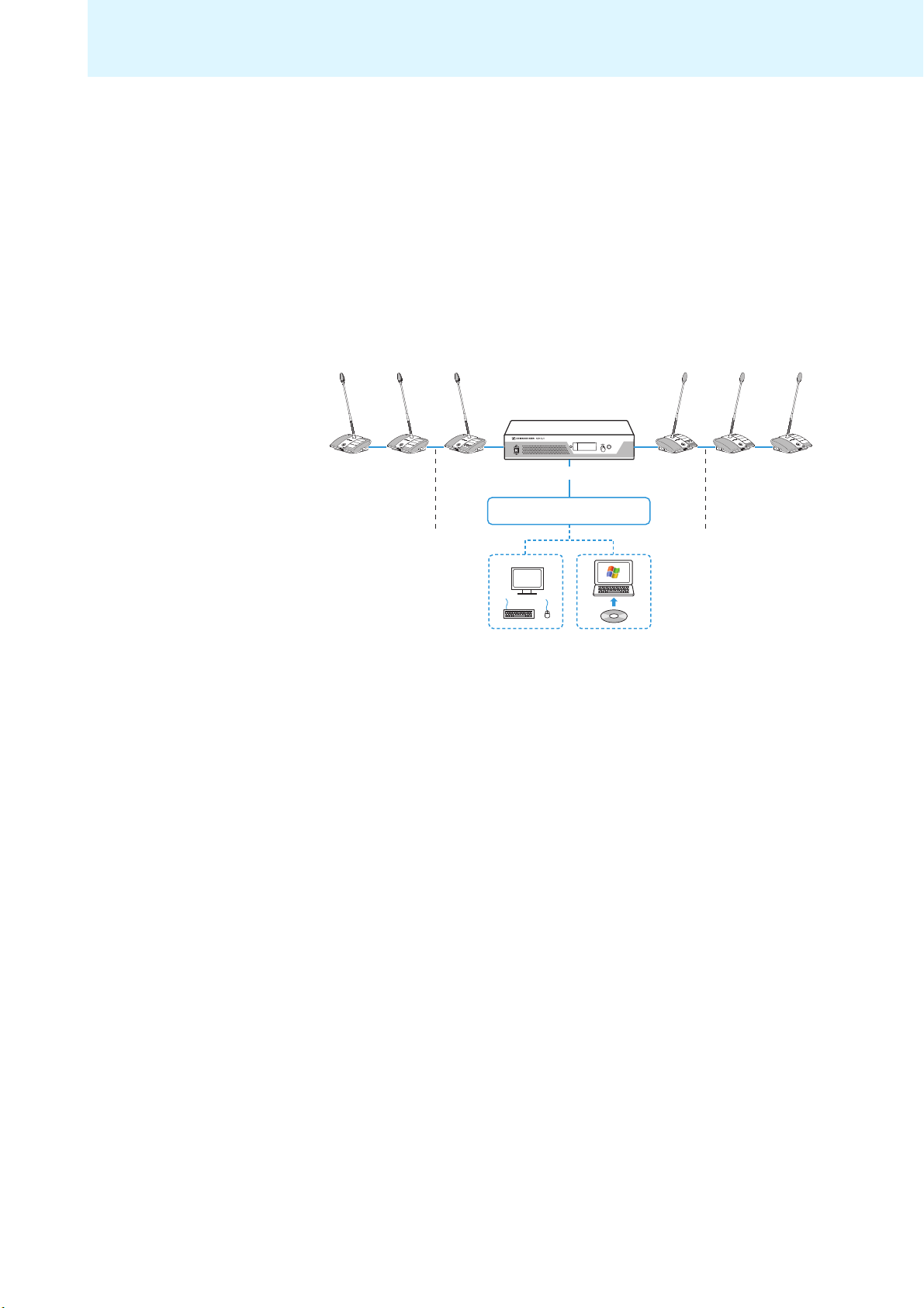
Overview of the components
Overview of the components
For conferencing, you require:
•1 ADN CU1 central unit
•ADN D1 delegate units
•ADN C1 chairman units (optional, for gr
• SDC CBL RJ-45 system cables (available in different lengths)
• “Conference Manager” software for conf
(optional)
– can be run on the central unit (a screen, keyboard, and mouse are required)
or
– can be run on a separate Windows PC wi
ting speaking privileges)
an
guring and controlling conferences
i
th Ethernet connection
ESC
ADN D1/ADN C1
SDC CBL RJ-45 SDC CBL RJ-45
ADN CU1
Conference Manager software
ADN D1/ADN C1
7
Page 9
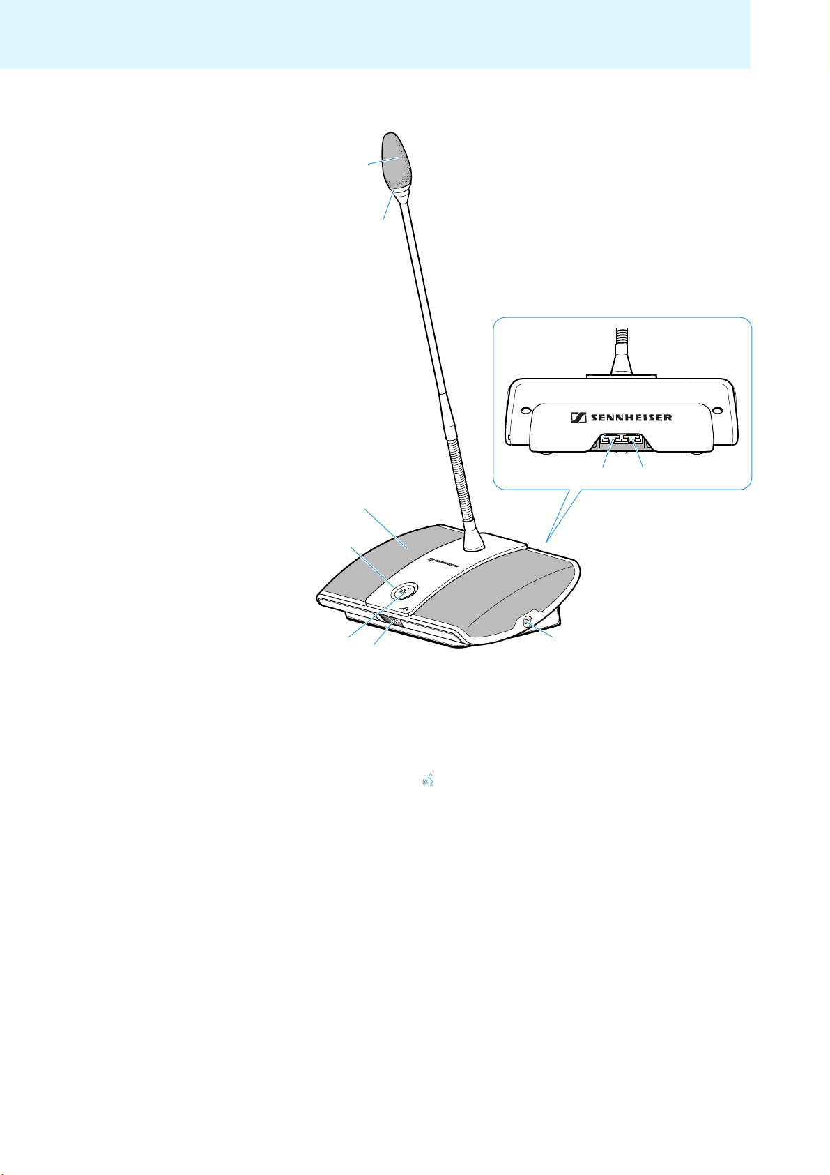
Overview of the components
쐋
ADN D1 delegate unit
Sound inlet basket
with firmly fixed windshield
Signal light ring OUT socket
Headphone socket
Headphone volume control
headphone socket
Microphone key
Microphone LED
Loudspeaker
for
IN socket
8
Page 10
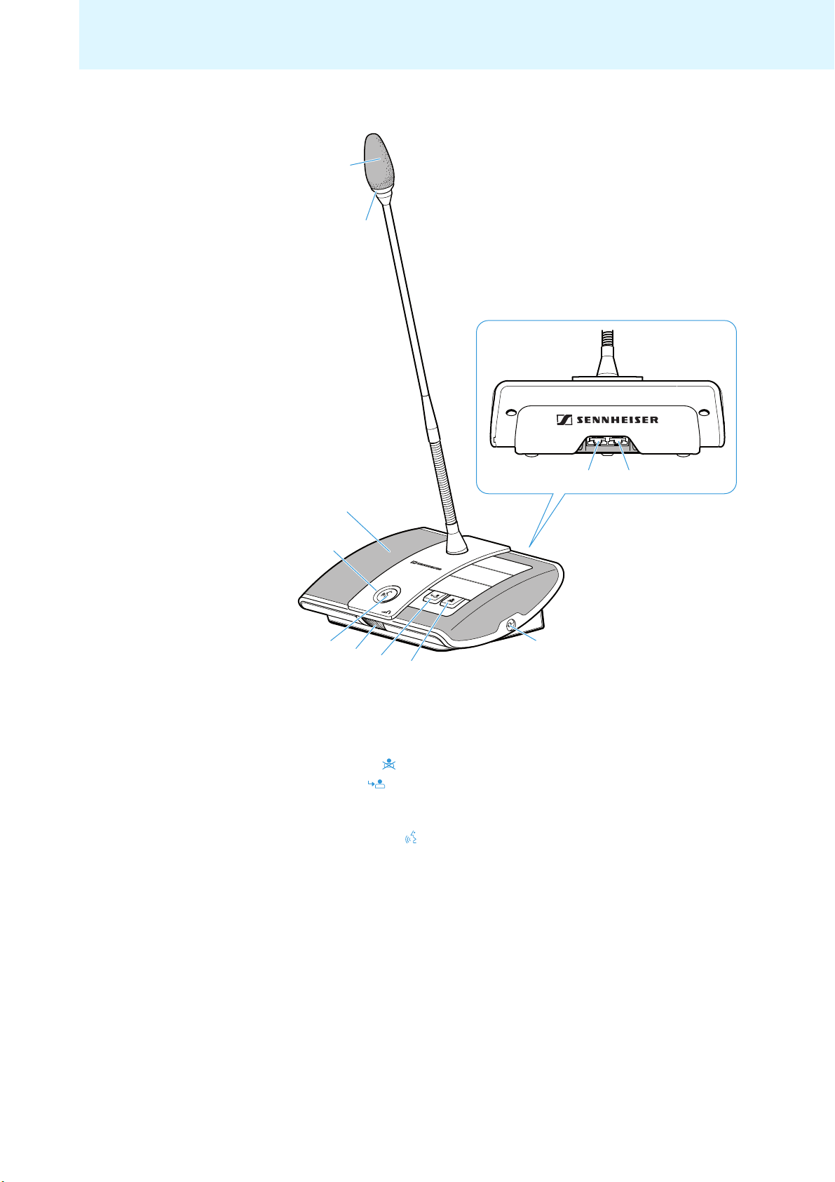
ADN C1 chairman unit
쐋
Overview of the components
Sound inlet basket
with firmly fixed windshield
Signal light ring OUT socket
Headphone socket
Priority key
Next key
Headphone volume control for
headphone socket
Microphone key
Microphone LED
Loudspeaker
IN socket
9
Page 11
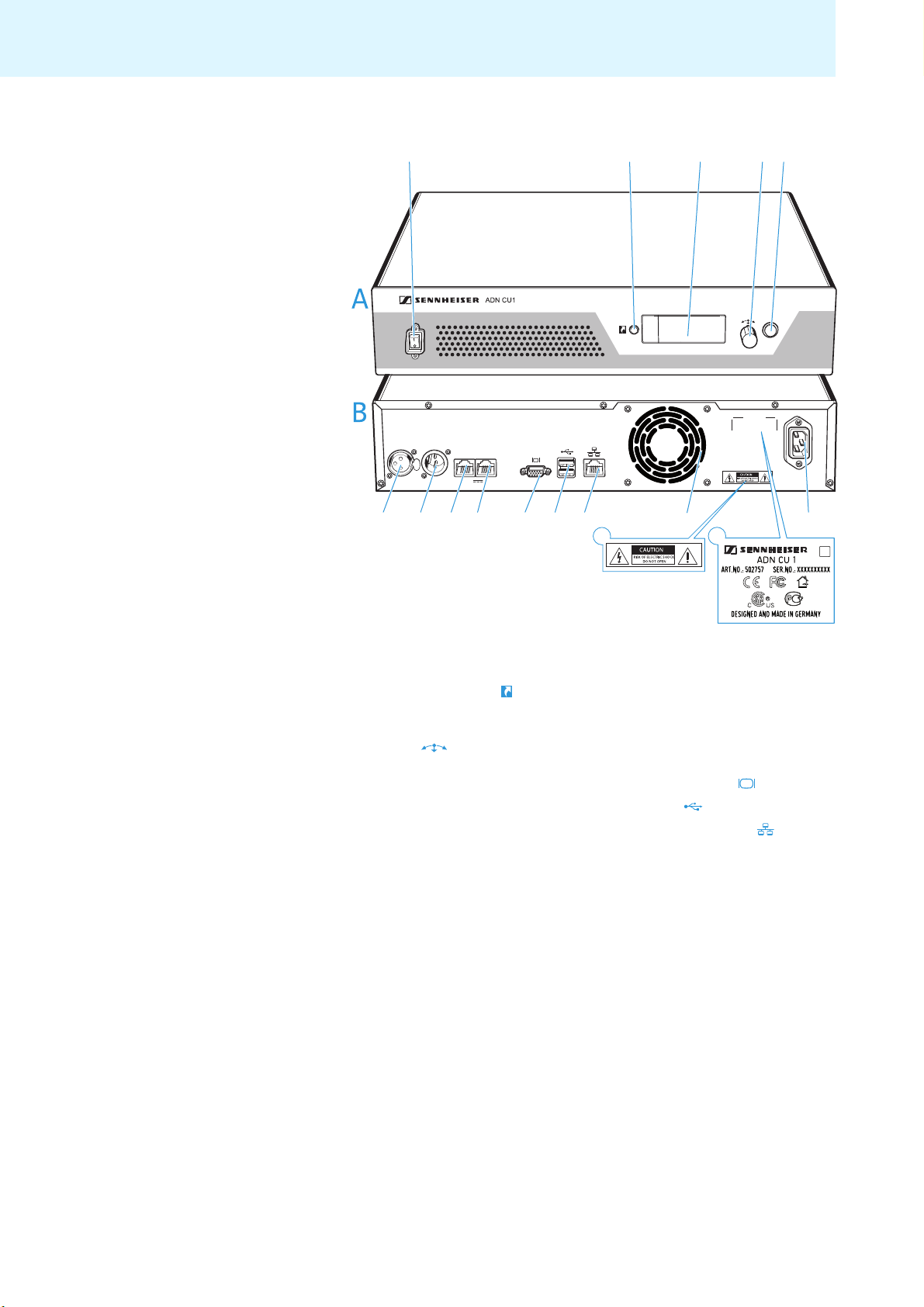
Overview of the components
IN –– AUDIO –– OUT
PORT II PORT I
100-240V~
50/60Hz 240W
2x 52.8V 1.75A
ESC
1
6 7 8 9 @ A B
C
E
F
D
2345
1
6
27384
9
50A
BCD
E
F
ADN CU1 central unit
A Front view B Rear view
On/off switch IN audio input
Standard display key
Display panel PORT II socket (RJ 45) for connection
Jog dial
ESC key (Escape) VGA monitor output
OUT audio output
of co
rence units
nfe
PORT I socket (RJ 45) for connection
of confe
rence units
USB socket (2x)
Network socket (RJ 45)
Fans
Mains socket
Hazard warnings
Type plate
10
Page 12
Overview of the components
GHIJKLMNO
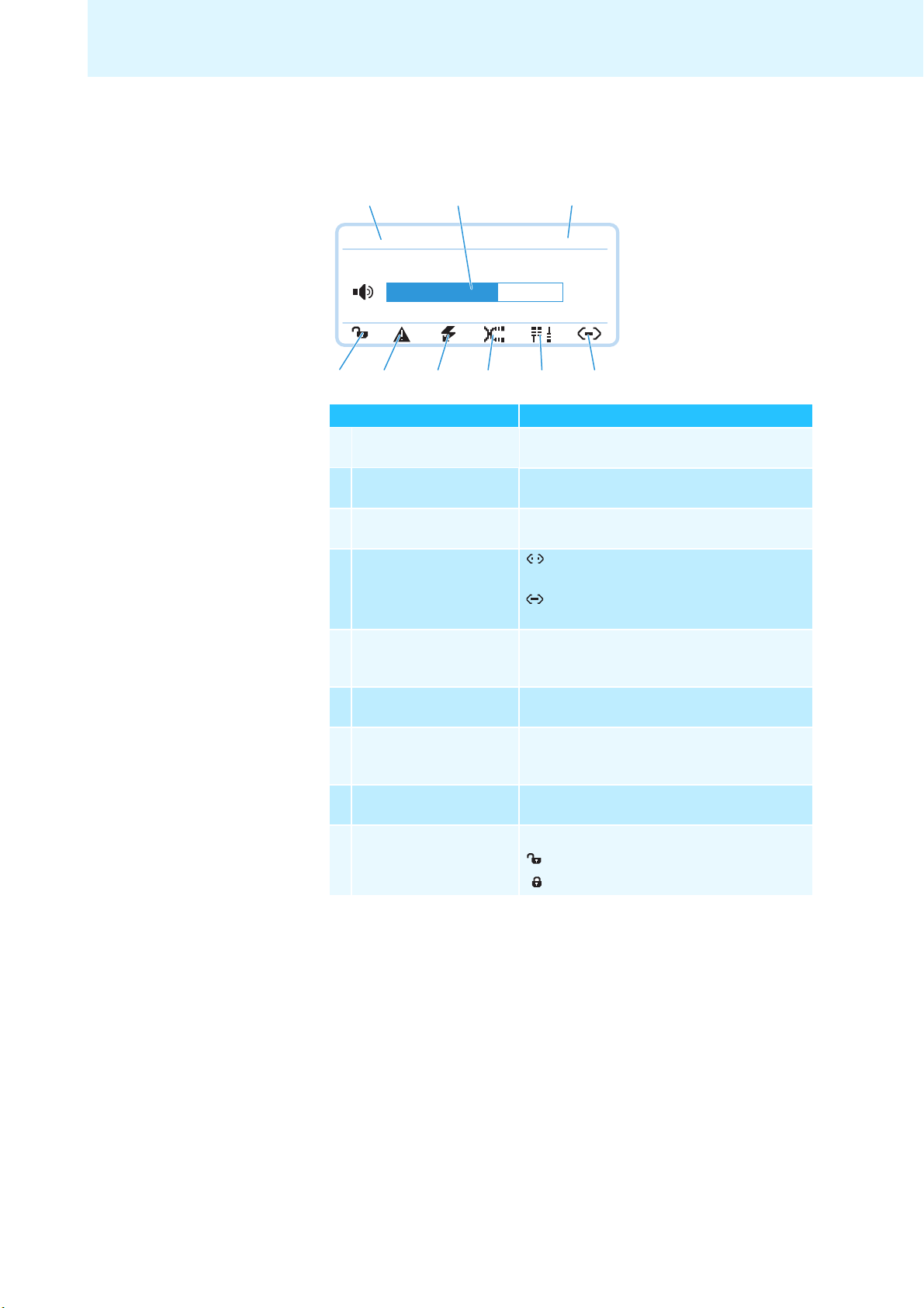
Overview of the ADN CU1 display panel
After switch-on, the central unit’s display shows a progress bar for approx.
30 seconds and then the standard display:
G
Direct Access
H
I
30 Units
22
O
N
Text/icon Possible display/function
Conference mode Current conference mode:
Floor channel volume Current volume setting for the conference units’
Number of
conference units
Connection status : “Conference Manager” software is not
Structural change icon Icon appears if, since the last initialization, a
Cable fault icon Icon appears if conference units are not correctly
Short-circuit icon Icon appears if there is a short circuit in the
Warning triangle Icon appears if there is a malfunction/change
Lock mode icon
(see page 21)
M
L
K
“Direct Access”, “Override”, “Request
built-in loudspeakers
Number of connected conference units
connected to the central unit
connected to the central unit
malfunction/change has occurred in the wiring
of the conference units (see page 34
connected (see page 34)
wiring of the conference units (see page 34).
The display panel lights up red.
(see page 34
Lock mode of the central unit:
: Lock mode is deactivated
: Lock mode is activated
J
: “Conference Manager” software is
). The display panel lights up red.
)
”
11
Page 13

Overview of the components
P
R
P
Q
S
PQR
S
The “Conference Manager” software
The “Conference Manager” software allows you to conveniently configure and
control the entire conference via a Windows PC or directly via the central unit.
For further information on the software, refer to the chapter “Using the “Conference Manager” software” on page 49.
The SDC CBL RJ-45 system cables
The system cables transmit the digital audio and status information and supply
power to the conference units.
Shielded RJ 45 modular plug, cat 5(e)
Gray cable booth with clip protector
Round STP cable, cat 5(e), 24 AWG, black
Black cable booth with clip protector
12
Page 14
Structuring and controlling the conference system
1 2 15
...
1 2 15
...
Voltage supply = 52.8 V
>35 V >35 V
IN –– AUDIO –– OUT
PORT II PORT I
100-240V~
50/60Hz 240W
2x 52.8V 1.75A
max. 80 mapprox. 2-5 m approx. 2-5 m
Port I
Port II
approx. 2-5 m approx. 2-5 m
Structuring and controlling the
conference system
Structuring the conference system
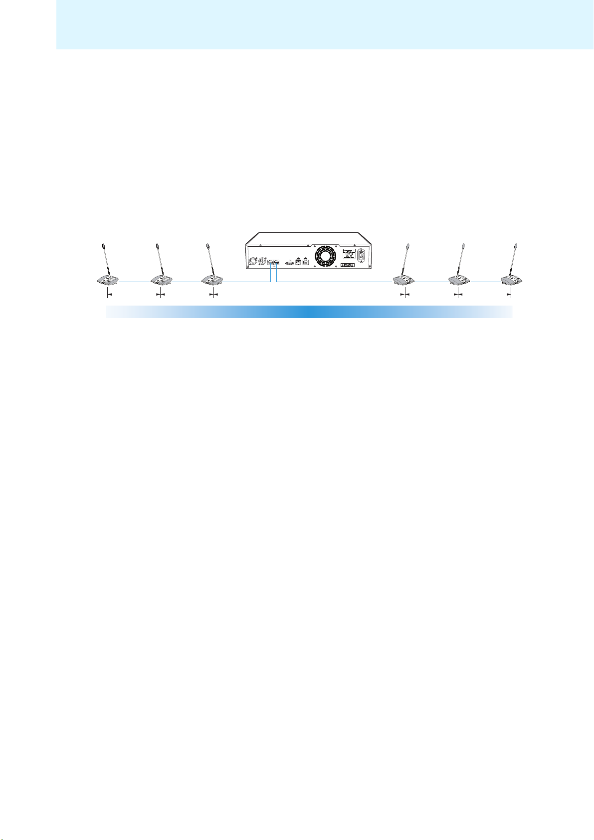
The ADN conference system is suitable for sm
approx. 30 conference units (divided up onto the two connection sockets PORT I
and PORT II). Delegate units and chairman units can
order and are connected to the central unit using SDC CBL RJ-45 system cables. The
ends of the cable strings are open (no ring topology). The maximum number of
conference units that can be used depends on the voltage supply which in turn is
influenced by the cable lengths (see next chapter).
all to medium size conferences with
be combined in an arbitrary
In addition, you can connect audio devices to the central unit in order to e.g. feed
audio signals to the floor channel or to output the floor channel via an external
audio device.
Calculating the voltage drop on the system cables
For safe operation of the conference system, make sure that all
conference units
are supplied with a voltage of at least 35 V! The voltage supplied depends on the
number of connected conference units and on the cable lengths. The standard
cable length between the central unit and the first conference unit is 80 m max.
and the stand
ard cable length between the conference units is 2-5 m. If these cable
lengths are observed, safe operation of a conference system with 30 conference
units is ensured. If cable lengths are shorter, it might be that more conference units
can be used.
ate
The “ADN Cable Calculator” program allows you to calcul
the voltage drops on
the individual sections of a cable string and to plan the structure of the conference
system. The program is available from your Sennheiser partner or from the download area on our website at www.sennheiser.com.
To use the “ADN Cable Calculator” program:
왘 Start the “ADN Cable Calculator.exe” file and follow the instructions of the
og
ram.
pr
For further information and for how to calculate the voltage drop of a cable str
ing,
refer to the help of the “ADN Cable Calculator” program.
13
Page 15
Structuring and controlling the conference system
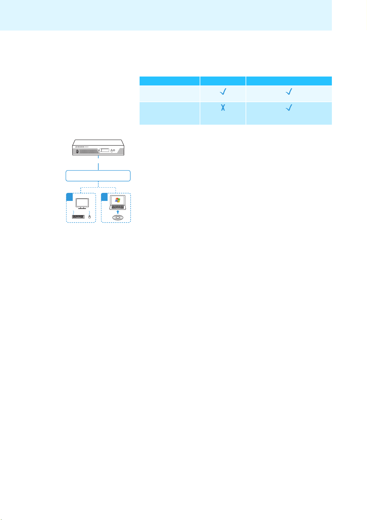
Configuring and controlling the conference system
For configuring the conference system, you can either
the central unit or the “Conference Manager” software. The software also allows
you to control conferences via a graphical interface:
Function Operating menu “Conference Manager” software
Configuring the
conference
Controlling the
conference via a
graphical interface
The “Conference Manager” software can be run in two different ways:
a) As a program on the central unit’s built-in PC.
ESC
u have to connect a screen, keyboard, and mouse to the central unit
Yo
(see page 50).
ADN CU1
Conference Manager software
b) As a program on a Windows PC.
You have to install the “Conference Manager” software on the PC and integrate
the PC together with the central unit in a network (see page 50).
a b
use the operating menu of
14
Page 16
Putting the conference system into operation
U
U
U
Putting the conference system into
operation
Preparing the central unit for use
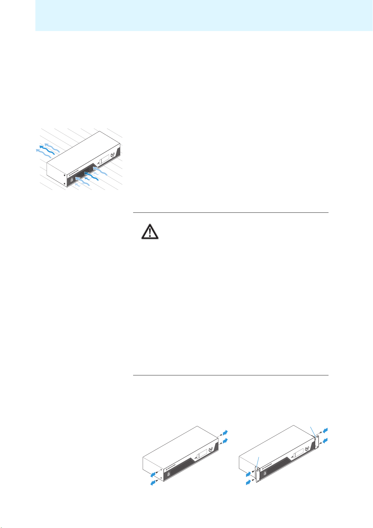
Setting up the central unit on a flat surface or mounting it into a rack
If you want to place the central unit on a flat surface:
왘 Make sure that the air vents are not covered or blocked.
왘 Place the central unit on a flat surface as shown.
If you want to mount the central unit into a 19” rack, the central unit must be
supported and
fixed to the rack using additional components.
Fastening the optional
rack mount “ears”
CAUTION Danger of material damage and personal injury when rack
mounting the central unit!
When installing the product in a closed or multi-rack assembly,
se consider that, during operation,
plea
• the ambient temperature within
increase,
• high mechanical loading may occur,
• intrinsically harmless leakage currents of the
units may accumulate, thereby exceeding the allowable limit
value.
This can cause material damage and
왘 Always mount the central unit using a suitable rack tra
sure that the mechanical loading of the rack is even.
왘 Make sure that the ambient temperature wi
exceed the permissible temperature limit specified in the specifications (see page 109). Ensure sufficient ventilation; if necessary,
provide additional ventilation.
왘 When connecting to the power supply, observe the in
indicated on the type plate. Avoid circuit overloading. If necessary, provide overcurrent protection.
왘 Ground the rack via an additi
왘 Unscrew and remove the 2 torx screws (T25) on each side of the central unit
(s
ee left-hand diagram).
왘 Secure the optional rack mount “ears” (see “Accessories” on page 108) to
the sides of the central unit using the pre
right-hand diagram).
the rack may drastically
individual mains
electric shocks.
y. Make
thin the rack does not
formation
ona
l ground connection.
v
iously removed torx screws (see
15
Page 17
Putting the conference system into operation
100-240V~
50/60Hz 240W
D
D
왘 Slide the central unit with the mounted rack mount “ears” into the 19” rack
왘 Secure the rack mount “ears” to the rack.
and support the weight with e.g. a rack tray.
An engineering drawing detailing the di
mensions of the
central unit can
be found in the appendix (see page 111).
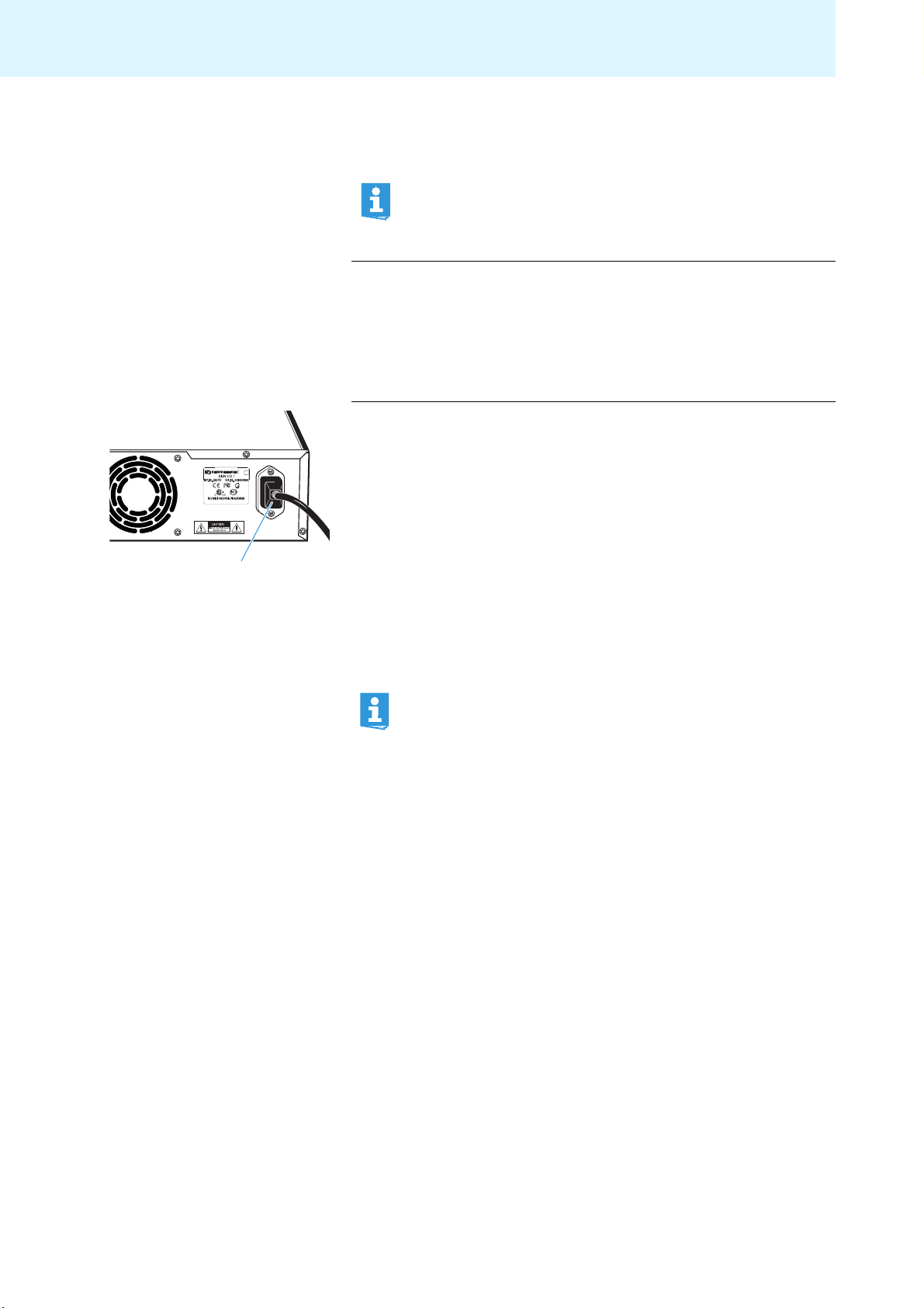
Connecting the central unit to the mains
CAUTION Product damage due to unsuitable mains cables or power outlets!
An unsuitable power supply can damage the product.
왘 Only use the recommended mains cable (see “Accessories” on
page 108) for connecting the product to the mains.
왘 Only use multi-outlet power strips or extension
cables with
protective ground contacts.
왘 Only use mains cables with a 3-pin connector.
왘 First connect the mains cable to the mains socket .
왘 Connect the mains cable to the mains.
The central unit is now ready for operation.
Preparing the conference units for use
The conference units are ready for operation upon delivery. The conference system
automatically recognizes if the connected conference units are chairman units or
delegate units and initializes them automatically.
If you connect chairman units to the conference system during a running
conference, you have to re-initialize them (see page 30 or page 88).
16
Page 18
Putting the conference system into operation
IN OUT
IN OUT
IN –– AUDIO –– OUT
PORT II PORT I
100-240V~
50/60Hz 240W
2x 52.8V 1.75A
8 9
8
9
Setting up the conference system
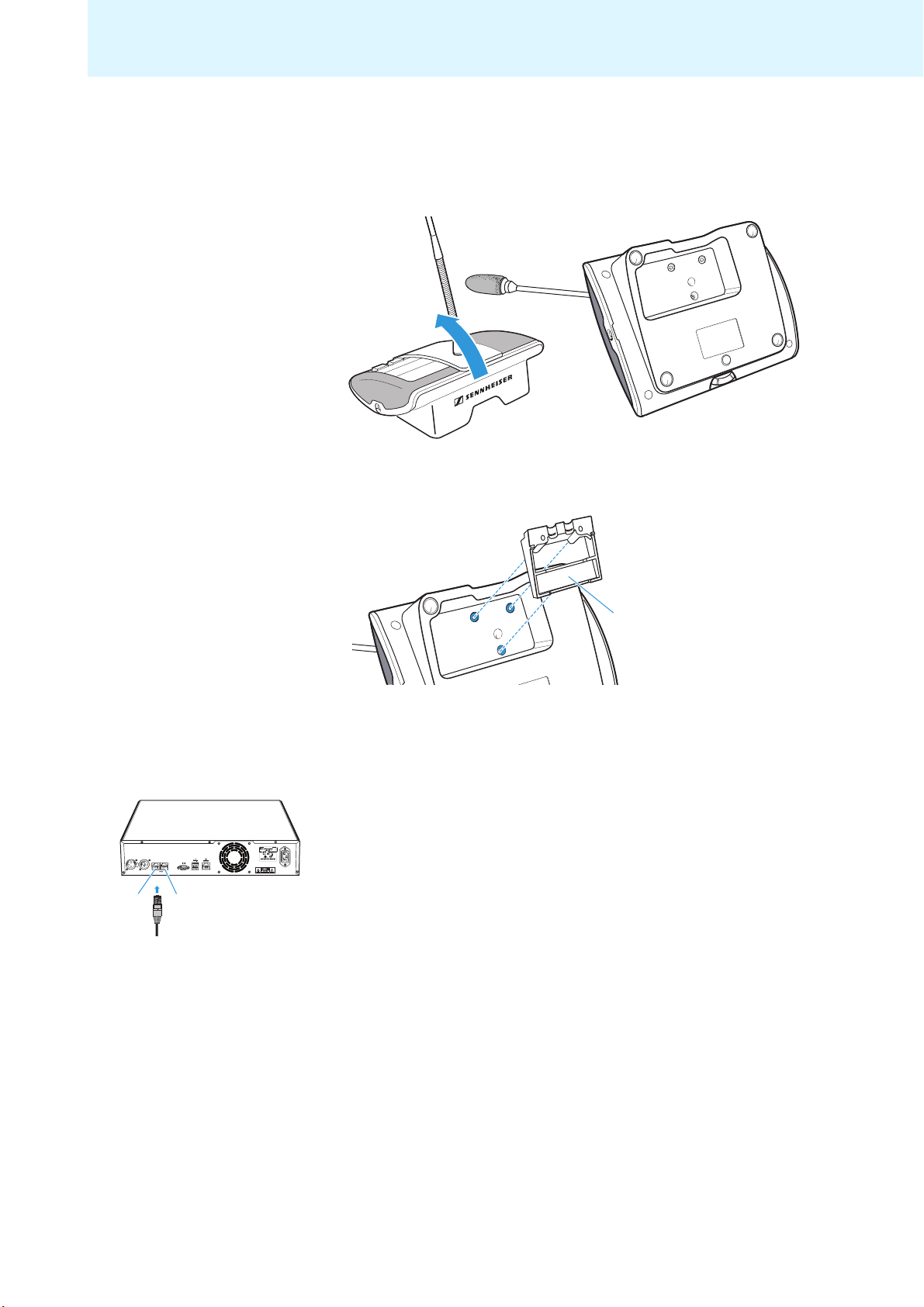
Installing the cable holder
If you want to permanently install your conference
optional cable holders (see “Accessories” on page 108).
왘 Tilt the conference units as shown.
왘 Hold the conference units with one hand so that the microp
on the table.
system in a room, use the
hone does not rest
왘 Insert the cable holder as shown.
At this point, the cable holder is not yet fixed with screws. You first have to
connect the conference units as described in the following chapter.
Connecting the conference units to the central unit
You can connect up to 15 conference units to each of the central unit’s connection
sockets PORT II or PORT I . The maximum number of conference units that can
be used in one cable string depends on the ov
erall cable length connected to a port
(see page 13).
The following describes the pr
ocedure for one cable string. If necessary, repeat
these steps for a second cable string.
왘 Place the conference units at the corresponding seats.
왘 Put out a sufficient number of system cables in the re
quired lengths (se
“Accessories” on page 108).
of the
왘 If necessary, calculate the maximum length
cable string in order to
ensure that all conference units connected in the string are supplied with a
voltage of at least 35 V (see page 13).
e
17
Page 19
Putting the conference system into operation
IN OUT
IN OUT
89
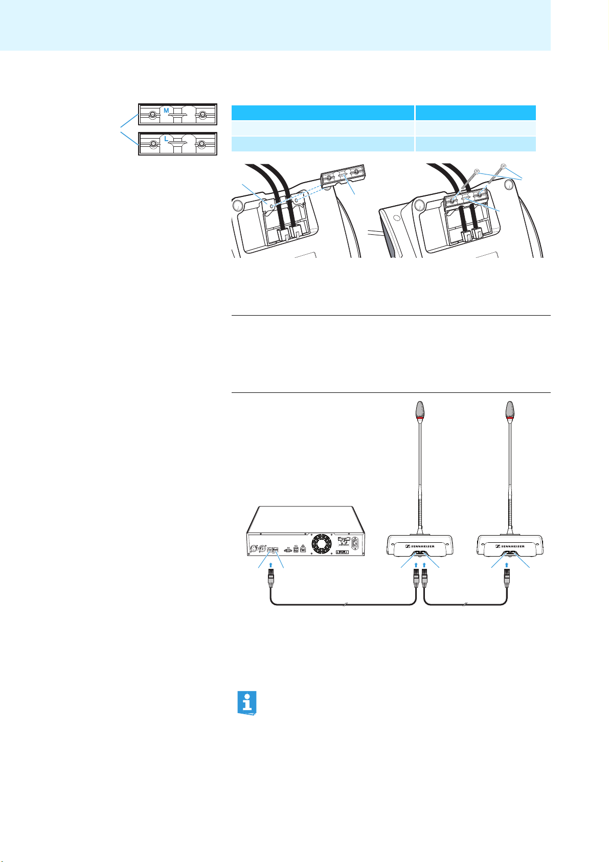
If you are using cable holders (see previous chapter):
왘 Choose a suitable cover for the cable holder :
Cable Cable holder cover
SDC CBL RJ 45 system cable marked “M”
Highly shielded cable marked “L”
왘 Affix the covers as shown.
왘 Slightly tighten the suppl
To connect the conference units to the central unit:
ied screws (approx. 0.05 Nm).
CAUTION Product damage due to an unsuitable power supply!
An unsuitable power supply can damage network devices with RJ 45
plugs that are connected to the
connection sockets PORT I and
PORT II.
왘 Only connect ADN C1 and ADN D1 conference units to the connec-
tion sockets PORT I and PORT II.
18
IN –– AUDIO –– OUT
PORT II PORT I
2x 52.8V 1.75A
8 9
50/60Hz 240W
100-240V~
IN OUTIN OUT IN OUT
왘 Use a system cable to connect the IN socket of the first conference unit to
the PORT II socket or PORT I socket of the central unit (see above).
왘 Use a system cable to connect the OUT
socket of the first conference unit
to the IN socket of the second conference unit.
왘 Repeat these steps for the remaini
ng conference units.
Please note that there is a limited number of approx. 15 conference units
per cable string due to the voltage drop on the cable string (see page 13).
Page 20

7
7
6
0
A
IN –– AUDIO –– OUT
Putting the conference system into operation
Connecting external audio devices to the central unit
To output the floor channel via an external audio device:
왘 Use an XLR cable to connect the OUT audio output of the central unit to an
external audio device.
PORT II PORT I
2x 52.8V 1.75A
IN –– AUDIO –– OUT
PORT II PORT I
2x 52.8V 1.75A
6
Running the software installed
on the
central unit
To connect an external audio source and to
feed its signals to the floor channel:
왘 Use an XLR cable to connect the external audio source to the IN audio input
of the central unit.
Preparing to use the “Conference Manager” software
To use the “Conference Manager” software installed on the central unit, you require
the following devices:
Device Requirements
Screen Connection: 15-pin Sub-D VGA
Resolution: 800 x 600 pixels or higher
Recommended: 1024 x 768 or 1280 x 1024 pixels
Mouse Standard USB for Windows PCs
Keyboard Standard USB for Windows PCs
Supported language layouts: e.g.
English, German, French,
Spanish, Italian, Russian, Dutch (for the complete list, see
“Keyboard layouts” on page 112)
왘 Use a Sub-D VGA cable to connect a screen to the VGA monitor output .
IN –– AUDIO –– OUT
PORT II PORT I
2x 52.8V 1.75A
100-240V~
50/60Hz 240W
0
왘 Connect the keyboard and the mouse to the two USB sockets .
IN –– AUDIO –– OUT
왘 Configure the screen, keyboard and mous
PORT II PORT I
2x 52.8V 1.75A
100-240V~
50/60Hz 240W
Manager” software (see page 63).
Your conference system is now ready for operation.
e settings using the “Conference
A
The USB sockets only support a keyboard and a mouse.
19
Page 21

Putting the conference system into operation
IN –– AUDIO –– OUT
PORT II PORT I
100-240V~
50/60Hz 240W
2x 52.8V 1.75A
B
B
1
1
Running the software on a
separate Windows PC
1
To run the “Conference Manager” software on a separate Windows PC, the PC must
meet the system requirements listed on page 50.
왘 Use a network cable (Cat5) to connect the Ethernet socket of the central
unit to the network interface of your PC.
You can also connect the PC and the central unit using a switch or similar.
왘 Install the “Conference Manager” software supplied on the CD ROM on your
connected PC (see page 51).
왘 Configure the network as described in the chapter “Preparing the Windows
version of the software for use” on page 50.
Switching the conference system on/off
To switch the conference system on:
왘 Set the on/off switch to position “I”.
The central unit switches on and its display panel lights up.
To switch the conference system off:
If you have made changes to a configuration using the “Conference
Manager” software, you have to save these changes before switching the
central unit off (see page 69). All other settings of the central unit are
automatically saved.
왘 Set the on/off switch to position “0”.
The central unit is switched off completely.
20
Page 22
Using the central unit
Using the central unit
Deactivating the lock mode of the central unit
If the lock mode is activated (see page 43), you have to deactivate it in order to be
able to operate the central unit:
왘 Press the jog dial or any other key.
“Lock” appears on the display panel.
왘 Turn the jog dial.
The “OFF” setting is selected.
왘 Press the jog dial.
The lock mode is deactivated.
Functions of the keys
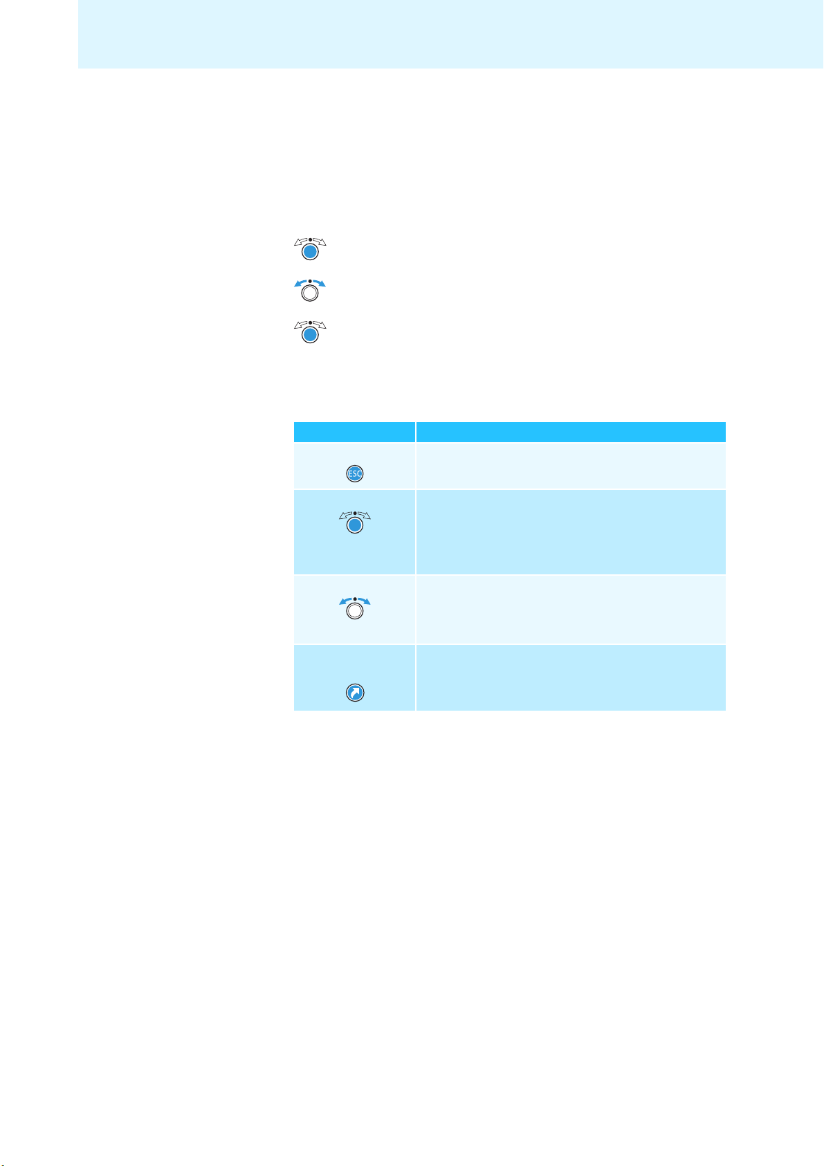
Action Functions
Press the ESC key • Cancels the entry and returns to the next higher
menu level or to the standard display
Press the jog dial • Changes from the standard display to the
operating menu
• Calls up a menu item
• Enters a submenu
• Stores the settings and returns to the operating menu
Turn the jog dial • Increases or reduces the floor channel volume
(when the standard display is shown)
• Changes to the next/previous menu item
• Changes the setting of a menu item
Press the standard
display key
• Returns to the standard display
21
Page 23

Configuring the conference system via the central unit
Configuring the conference system via the central unit
Overview of the operating menu
“Conference”
submenu
“Main Menu”
Conference
Audio
System
Languages
Settings
Conference Mode
Microphone Limit
Request Limit
Talk Time Status
Talk Time Limit
Premonition Time Limit
Reaction on Talktime
Exceed
Blink on Request
Re-Init
Clear Request List
on Cancel
“Audio”
submenu
XLR Out
XLR In
Floor/Loudspeakers
Audio Gain Reduction
“XLR Out”
submenu
XLR Out Status
XLR Out Volume
XLR Out Equalizer
“XLR In”
submenu
XLR In Status
XLR In Sensitivity
XLR In Equalizer
“Floor/Loudspeakers”
submenu
Floor/Loudspeaker
Volume
Floor/Loudspeaker
Equalizer
“System”
submenu
Ports
Diagnostics
Versions
“Settings”
submenu
Network
Contrast
Lock
Restore Factory Defaults
“Diagnostics”
submenu
System Load
Temperature
Bus Statistics
Start Self-Test
Reset Break Indication
Reset Error Indication
“Versions”
submenu
Hardware Versions Info
Software Versions Info
“Network”
submenu
IP Address Mode
IP Address
Subnet Mask
22
Page 24

Configuring the conference system via the central unit
Display Function of the menu item Option/display Page
“Main Menu”
“Conference” Calls up the “Conference” submenu – 26
“Audio” Calls up the “Audio” submenu – 31
“System” Calls up the “System” submenu – 34
“Languages” Adjusts the language “Deutsch”, “English”,
41
“Espanol”...
“Settings” Calls up the “Settings” submenu –
“Conference” menu
“Conference
Mode”
“Microphone
Limit”
“Request Limit” Sets the maximum number of requests to speak in “Request”
Adjusts the conference mode “Direct Access”,
“Override” or “Request”
Sets the maximum number of speakers who can take the
“1” ... “10” 27
floor simultaneously in “Direct Access” and “Override” mode
“0” ... “10” 28
26
and “Direct Access” mode
“Talk Time Status” Activates/deactivates the speaking time limit “On“/“Off” 28
“Talk Time Limit” Sets the speaking time limit “01” ... “60”
28
in steps of 1 minute
“Premonition Time
Limit”
“Reaction on
Talktime Exceed”
“Blink on Request” Activates/deactivates the flashing of the signal light ring
Sets the advance warning time (warns speakers that they
are approaching the end of the individual speaking time)
Determines the behavior when the individual speaking time
is exceeded
“00” ... “120”
in steps of 10 seconds
“Continue“/“Cancel” 29
“On“/“Off” 30
28
when a request to speak is made
“Re-Init” Re-initializes the conference units “Yes“/“No” 30
“Clear Request List
Sets the function of the priority key of the chairman unit
“On“/“Off” 30
on Cancel”
“Audio” menu
“XLR Out” Calls up the “XLR Out” submenu – 31
“XLR In” Calls up the “XLR In” submenu –
“Floor/
Calls up the “Floor/Loudspeakers” submenu –
Loudspeakers”
“Audio Gain
Reduction”
The sum signal of all active conference units is output via
the floor channel (“Floor/Loudspeakers”). The “Audio Gain
Reduction” menu item allows you to adjust how the volume
“0.0 dB per Mic” ...
“−3.0 dB per Mic”,
“Linear Division”
32
levels of the signals of the individual conference units are
processed.
“XLR Out” menu
“XLR Out Status” Activates/deactivates the OUT audio output “On“/“Off” 31
“XLR Out Volume” Adjusts the volume of the XLR output
“01” ... “32”
“XLR Out
Equalizer”
Adjusts the tone color of the XLR output
+02 dB
–03 dB
+05 dB
“−12 dB” ... “+12 dB”
23
Page 25
Configuring the conference system via the central unit
Deleg Chair.
Port1: xx xx Units
Port2: xx xx Units
DU/PU: 1
CU SB: 1
DU/PU: 0.1.1.5
CU SB: 1.0.0.0
CU Main: 1.0.0.1
Display Function of the menu item Option/display Page
“XLR In” menu
“XLR In Status” Activates/deactivates the IN audio input “On“/“Off” 31
“XLR In
Sensitivity”
Adjusts the sensitivity of the XLR input
“−18.0 dBu” ...
“+18.0 dBu”
“XLR In Equalizer” Adjusts the tone color of the XLR input
+02 dB
–03 dB
+05 dB
“−12 dB” ... “+12 dB”
“Floor/Loudspeakers” menu
“Floor/
Loudspeakers
Volume”
“Floor/
Loudspeakers
Equalizer”
Adjusts the floor channel volume (“Floor/Loudspeakers”)
Adjusts the tone color of the floor channel
“00” ... “32”
+02 dB
–03 dB
+05 dB
“−12 dB” ... “+12 dB”
32
“System” menu
“Ports” Displays the type and number of the conference units
37
connected to Port I and Port II
“Diagnostics” Calls up the “Diagnostics” submenu – 38
“Versions” Calls up the “Versions” submenu – 41
“Diagnostics” menu
“System Load” Provides information on the current and voltage supply 38
“Temperature” Provides information on the temperature status 39
“Bus Statistics” Provides information on the status of data transmission/
errors
Error Indication :
Break Count : 1
39
“Start Self-Test” Performs a self-test on the conference system “On“/“Off” 40
“Reset Break
Indication”
“Reset Error
Indication”
Resets the error counter (“Break Count”) in the
“Bus Statistic” menu item
Resets the display for data bus errors (“Error Indication”) in
the “Bus Statistic” menu item
“Yes“/“No” 40
“Yes“/“No” 40
“Versions” menu
“Hardware Version
Displays the hardware version 41
Info”
“Software Version
Info”
24
Displays the software version 41
Page 26

Configuring the conference system via the central unit
Select and call up the
“Conference” submenu
Select and call up the
“Microphone Limit”
menu item
The “Microphone Limit”
menu item appears
Main Menu
Conference
Audio
System
Conference
Conference Mode
Microphone Limit
Request Limit
Microphone Limit
Conf. Mode
Microphones 05
No. Request
05 05
Select the desired
setting
Store the setting
Microphone Limit
Conf. Mode
Microphones 05
No. Request
Microphone Limit
Conf. Mode
Microphones 07
No. Request
05 07
Select and call up the
“Microphone Limit”
menu item
Conference
Conference Mode
Microphone Limit
Request Limit
5
Display Function of the menu item Option/display Page
“Settings” menu
“Network” Calls up the “Network” submenu – 42
“Contrast” Adjusts the contrast of the display panel “1” ... “15” 42
“Lock” Activates/deactivates the lock mode “On“/“Off” 43
“Restore Factory
Restores the factory default settings “Yes“/“No” 43
Defaults”
“Network” menu
“IP Address Mode” Sets the IP address allocation mode “Static IP“/“Dynamic IP” 42
“IP Address” Sets the IP address of the central unit “xxx . xxx . xxx . xxx” 42
“Subnet Mask” Sets the subnet mask of the central unit “xxx . xxx . xxx . xxx” 42
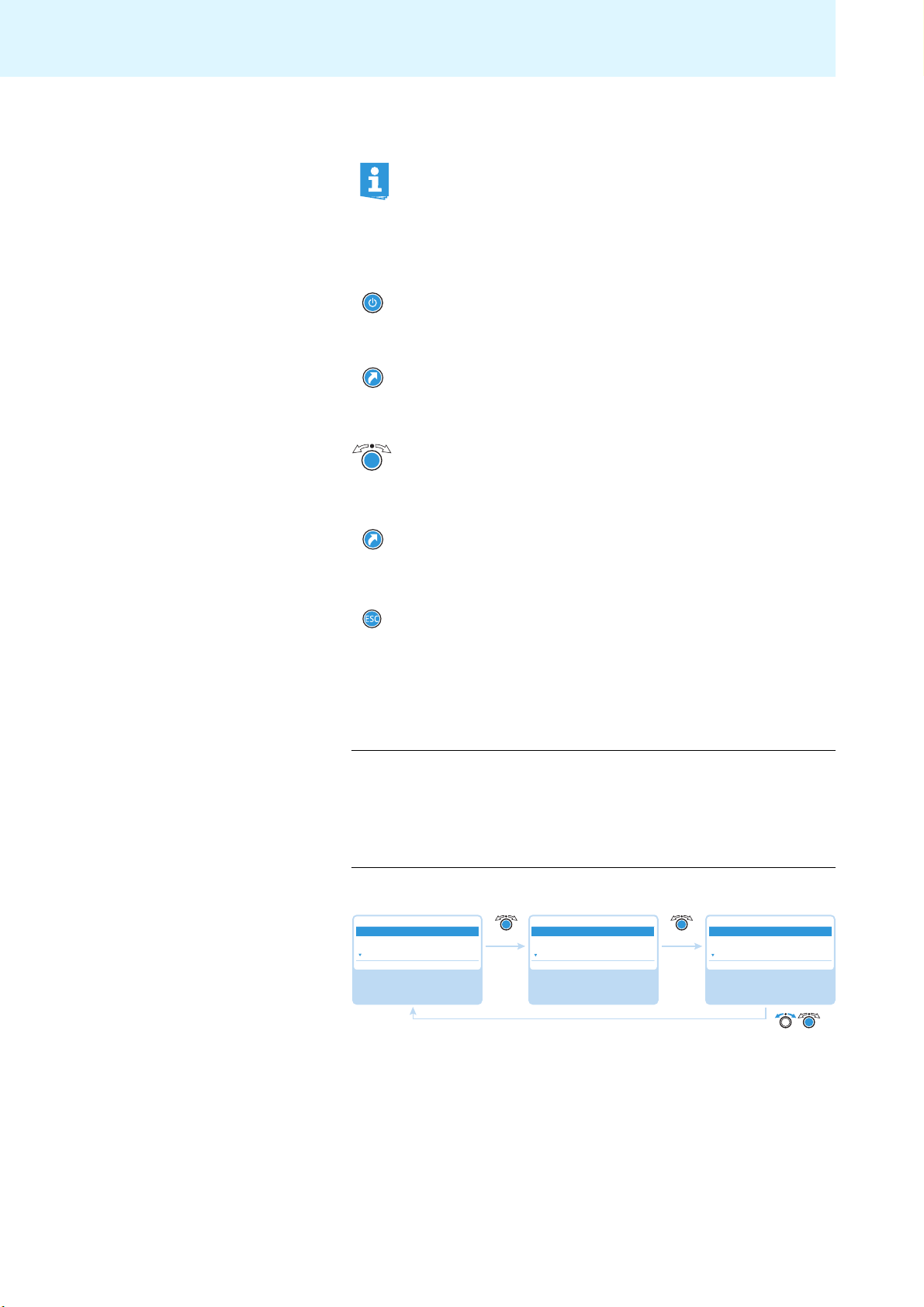
Working with the operating menu
By way of example of the “Microphone Limit” menu item, this section describes
how to use the operating menu.
Information on the factory default settings of
the appendix (see page 111).
the operating menu can be found in
Changing from the standard display to the operating menu
Direct Access
20
30 Units
Main Menu
Conference
Audio
System
“Main Menu”Standard display
왘 Press the jog dial.
The standard display is replaced by the main menu. The last selected menu
item is highlighted.
Calling up a menu item
왘 Press the jog dial to call up the “Conference” menu item.
The “Conference” submenu appears.
왘 Turn the jog dial to select the “Microphone Limit” menu item.
왘 Press the jog dial to call up the “Microphone Limit” menu item.
Changing and storing settings
왘 Turn the jog dial to adjust settings in the “Microphone Limit” menu item.
25
Page 27
Configuring the conference system via the central unit
왘 Press the jog dial.
Your setting is stored. You are back to the operating menu.
By briefly turning the jog dial to the left or right, the next or the previous
menu item or setting is displayed.
If you turn the jog dial to the left or right and hold it in this position, the
menu items or settings change in quick succession (“fast search” function).
Canceling an entry
왘 Press the ESC key.
The operating menu or the next highe
Or:
왘 Press the standard display key.
The standard display appears.
To subsequently directly return to the last edited menu item:
왘 Press the jog dial repeatedly until the last edited menu item appears.
Exiting the operating menu
r menu level appears.
왘 Press the standard display key.
The standard display appears.
Or:
왘 Press the ESC key repeatedly until the standard display appears.
Adjusting the conference settings – “Conference”
The settings available in the “Conference” menu item affect the behavior of the
entire conference system during a conference.
CAUTION Interruption of a running conference
If you adjust settings in the “Conference” menu item during a
running conference, the conference will be interrupted.
왘 Inform the participants that the conference settings are being
changed
speak.
Adjusting the conference mode – “Conference Mode”
Main Menu
Conference
Audio
System
Select and call up the
“Conference” submenu
and that they might have to make a new request to
Conference
Conference Mode
Microphone Limit
Request Limit
Select and call up the
“Conference Mode”
menu item
Conference Mode
Direct Access
Override
Request
Select the desired
setting; store the
setting
Direct AccessDirect Access
26
Possible settings: “Direct Access”, “Override” and “Request”.
•“Direct Access” mode and “Override” mode:
These two conference modes do not requir
e the use of a chairman unit.
Page 28

Configuring the conference system via the central unit
If the maximum number of speakers who can take the floor simultaneously
(“Microphone Limit”) has not been reached, a further speaker can take the
floor immediately.
Situation The maximum number of speakers who can take the floor
simultaneously (“Microphone Limit”) has been reached.
Event A further speaker presses the microphone key on his or her
conference unit.
Behavior In “Direct Access” mode:
The speaker has to wait until one of the current speakers passes
on or loses his or her speaking privileges. He is then automatically granted speaking privileges.
In “Override” mode:
The speaker can take the floor immediately. The speaker with
the longest speaking time loses his or her speaking privileges.
•“Request” mode:
For this mode to function, a chairman un
In “Request” mode, the chairman receives requests to
it is required.
speak and grants
speaking privileges according to the FIFO principle (First In – First Out), i.e. the
speaker with the longest waiting time is granted speaking privileges.
Situation The maximum number of requests to speak has been reached
(“Request Limit”).
Event A further speaker makes a request to speak.
Behavior The speaker can only make a request to speak if the maximum
number of requests to speak drops below the specified limit
value.
Setting the max. number of speakers who can take the floor simultaneously –
“Microphone Limit”
Main Menu
Conference
Audio
System
Select and call up the
“Conference” submenu
Conference
Conference Mode
Microphone Limit
Request Limit
Select and call up the
“Microphone Limit”
menu item
05
Microphone Limit
Conf. Mode
Microphones 05
No. Request
Select the desired
setting; store the setting
05
Adjustment range: “1” ... “10”
The “Microphone Limit” menu item allows you to set the max. number of speakers
who can take the floor simultan
eously in all conference modes. Please note that
any connected chairman unit is counted against the microphone limit. If you set a
higher value (adjustment range “1” ... “10”) than the one determined by the
i
number of connected cha
rman units, the system will reduce the microphone limit
to the maximum possible value (see examples in the table).
Chairman units Possible “Microphone Limit” values
0 “1” - “10”
4 “1” - “6”
10 “0”
For information on how this setting affects your conference, refer to the previous
section “Adjusting the conference mode – “Conference Mode””.
27
Page 29
Configuring the conference system via the central unit
Setting the maximum number of requests to speak – “Request Limit”
Main Menu
Conference
Audio
System
Select and call up the
“Conference” submenu
Adjustment range: “0” ... “10”
The setting adjusted in the “Request Limit” menu item becomes effective only if
u are using a chairman unit (“Request” mode) or if you have selected “Direct
yo
Access” mode.
For information on how this setting affects your conf
“Adjusting the conference mode – “C
Activating/deactivating the speaking time limit – “Talk Time Status”
Conference
Conference Mode
Microphone Limit
Request Limit
05 05
Select and call up
the “Request Limit”
menu item
onference Mode”” on page 26.
Request Limit
Conf. Mode
Requests 05
No. Request
Select the desired
setting; store the
setting
erence, refer to the section
Main Menu
Conference
Audio
System
Select and call up the
“Conference” submenu
Conference
Microphone Limit
Request Limit
Talk Time Status
Select and call up
the “Talk Time Status”
menu item
On On
Talk Time Status
On
Off
Select the desired
setting; store the
setting
Possible settings: “On” and “Off”
This menu item allows you activate/deactivate the speaking
tion of the speaking time limit, the advanc
e warning time, and the behavior after
time limit. The dura-
expiration of the speaking time limit can be set in the following 3 menu items.
Setting the speaking time limit– “T
Main Menu
Conference
Audio
System
Select and call up the
“Conference” submenu
alk Time Limit”
Conference
Request Limit
Talk Time Status
Talk Time Limit
Select and call up
the “Talk Time Limit”
menu item
05 Min 05 Min
Talk Time Limit
Conf. Mode
Minutes 05
Select the desired
setting; store the
setting
Adjustment range: “01” ... “60”, adjustable in steps of 1 minute
The speaking time limit becomes effective on
ly if it is activated in the “Talk Time
Status” menu item (see previous section).
Please note that the speaking time limit applies to each a
nd every input to the
discussion.
28
Setting the advance warning time – “Premoniti
Main Menu
Conference
Audio
System
Select and call up the
“Conference” submenu
Conference
Talk Time Status
Talk Time Limit
Premonition Time Limit
Select and call up the
“Premonition Time
Limit” menu item
on Time Limit”
Premonition Time Limit
Conf. Mode
Seconds 20
20 Sec 20 Sec
Select the desired
setting; store the
setting
Adjustment range: “00” ... “120”, adjustable in steps of 10 seconds
Page 30
Configuring the conference system via the central unit
왘 Set the advance warning time.
This setting affects your conference as follows (example):
“Talk Time Limit”
15 (minutes)
(speaking time limit)
“Premonition Time Limit”
60 (seconds)
(advance warning time)
Effect 60 seconds before the speaking time limit
expires, i.e. after 14 minutes in this example, the
signal light ring and the microphone LED
start flashing red.
Determining the behavior when the individual speaking time is exceeded
“Reaction on Talktime Exceed”
Main Menu
Conference
Audio
System
Select and call up the
“Conference” submenu
Conference
Talk Time Limit
Premonition Time Limit
Reaction on Talktime Exceed
Select and call up the
“Reaction on Talktime
Exceed” menu item
Continue Continue
Reaction on Talktime Exceed
Continue
Cancel
Select the desired
setting; store the
setting
Possible settings: “Continue” and “Cancel”
–
Event The end of the individual speaking time is reached.
Behavior “Continue”:
The individual speaking time is continued. The signal light ring
and the microphone LED flash red until the speaker has finished
speaking.
“Cancel”:
The individual speaking time is terminated. The signal light ring
and the microphone LED go off.
29
Page 31

Configuring the conference system via the central unit
Select and call up the
“Conference” submenu
Select and call up the
“Re-Init” menu item
Select the desired
setting; store the
setting
Main Menu
Conference
Audio
System
Conference
Reaction on Talktime exceed
Blink on Request
Re-Init
Re-Init
Yes
No
Select and call up the
“Conference” submenu
Select and call up the
“Clear Request List on
Cancel” menu item
Select the desired
setting; store the
setting
Main Menu
Conference
Audio
System
Conference
Blink on Request
Re-Init
Clear Request List on Cancel
Clear Request List on Cancel
On
Off
On Off
Activating/deactivating the flashing of the signal light ring when a request to
speak is made – “Blink on Request”
Main Menu
Conference
Audio
System
Select and call up the
“Conference” submenu
Conference
Premonition Time Limit
Reaction on Talktime exceed
Blink on Request
Select and call up the
“Blink on Request”
menu item
On On
Blink on Request
On
Off
Select the desired
setting; store the
setting
Possible settings: “On” and “Off”
Setting Behavior of the signal light ring
“On” When a participant makes a request to speak, the micro-
phone LED flashes green and the signal light ring
flashes red.
The participant him or herself sees the flashing microphone
LED whereas the other participants see the flashing
signal light ring which indicates that a request to speak
has been made.
“Off” When a participant makes a request to speak, the micro-
phone LED flashes green.
All other participants cannot see that this participant has
made a request to speak.
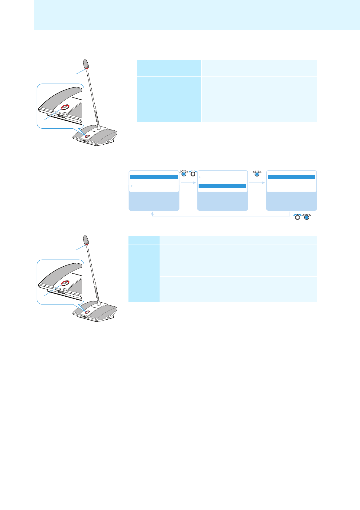
Re-initializing the conference units – “Re-Init”
If you connect chairman units to the conference system during a running conference, you have to re-initialize them.
When conference units are re-initialized, th
e conference will be interrupted.
30
Possible settings: “Yes” and “No”
Setting the function of the priority key
This menu item allows you to set the function of the chairman unit’s priority
key .
•Setting “On”: Pressing the priority key deactivates all delegate units.
All requests to speak are deleted.
•Setting “Off”: Pressing the priority key deactivates all currently
units.
All requests to speak are retained.
Possible settings: “On” and “Off”
– “Clear Request List on Cancel”
active delegate
Page 32

Configuring the conference system via the central unit
4
5
Adjusting the audio settings – “Audio”
The “Audio” submenu allows you to adjust settings that affect the audio signals of
the conference system.
Adjusting settings for the OUT audio output and the IN audio input – “XLR Out”
and “XLR In”
Main Menu
Conference
Audio
System
Select and call up the
“Audio” submenu
XLR Out Status/XLR In Status
On
Off
Select the “XLR Out
Status/XLR In Status”
setting; store the setting
On
Audio
XLR Out
XLR In
Floor/Loudspeakers
Select and call up
different submenus
XLR Out Volume
Conf. Mode
+6 dB
Off
XLR In Sensitivity
Select the “XLR Out
Volume/XLR In sensitivity”
setting; store the setting
No No
+6 dB
No No
+07.5 dBu
+07.5 dBu
No
XLR Out/XLR In
XLR Out Status/XLR In Status
XLR Out Volume/XLR In Sensitivity
XLR Out Equalizer/XLR In Equalizer
Select and call up
different menu items
XLR Out Equalizer/XLR In Equalizer
Conf. Mode + 02 dB
– 03 dB
Off + 05 dB
Select the “Equalizer”
setting; store the
setting
Submenu Menu item Function
“XLR Out” “XLR Out Status” Activates/deactivates the
OUT audio output
“XLR Out Volume” Adjusts the volume of the
OUT audio output
“XLR Out Equalizer” Adjusts the tone color
“XLR In” “XLR In Status” Activates/deactivates the
IN audio input
“XLR In Sensitivity” Adjusts the sensitivity of the
IN audio input (the current level
is displayed).
왘 Adjust the sensitivity so that
the level display shows an
almost full deflection at
maximum input volume.
“XLR In Equalizer” Adjusts the tone color
In the “Equalizer” menu item, you can change between the frequency
ranges by pressing the jog dial .
Press the ESC key to cancel your entry and restore the pr
evious state
of all frequency ranges.
31
Page 33

Configuring the conference system via the central unit
4
5
Adjusting settings for the floor channel – “Floor/Loudspeakers”
Main Menu
Conference
Audio
System
Select and call up the
“Audio” submenu
Audio
XLR Out
XLR In
Floor/Loudspeakers
Select and call up the
“Floor/Loudspeakerst”
menu item
Floor/Loudspeaker Volume
Conf. Mode
16
Off
Select the “Floor/Loudspeakers Volume” setting;
store the setting
No No
16
No No
Floor/Loudspeakers
Floor/Loudspeaker Volume
Floor/Loudspeaker Equalizer
Select and call up
different menu items
Equalizer
+ 02 dB
– 03 dB
+ 05 dB
Select the “Equalizer”
setting; store the
setting
Menu item Function
“Floor/Loudspeakers Volume” Adjusts the floor channel volume
“Floor/Loudspeakers Equalizer” Adjusts the tone color
In the “Equalizer” menu item, you can change between the frequency
ranges by pressing the jog dial .
Press the ESC key to cancel your entry and restore the previous state
of all frequency ranges.
Adjusting the processing of the conference units’ audio signals in the floor
channel – “Audio Gain Reduction”
Main Menu
Conference
Audio
System
Select and call up the
“Audio” submenu
Audio
XLR In
Floor/Loudspeakers
Audio Gain Reduction
Select and call up the
“Audio Gain Reduction”
menu item
- 0.0 dB per Mic - 0.0 dB per Mic
Audio Gain Reduction
- 0.0 dB per Mic
- 0.5 dB per Mic
- 1.0 dB per Mic
Select the desired
setting; store the
setting
Possible settings: “0.0 dB per Mic” ... “–3.0 dB per Mic” and “Linear Division”
The sum of the audio signals of all conference units is fed to the floor channel
(“Floor/Loudspeakers”) which in turn is output via the conference units’ built-in
o
udspeakers and via the OUT audio output. The volume level of the floor channel
l
increases with each additional audio signal* and tends to overmodulate. The
“Audio Gain Reduction” menu item allows you to adjust how the volume levels of
e signals of the conference units are processed.
th
Situation The audio signal of the 1. conference unit is fed to the floor channel.
Event The audio signal of another conference unit it fed to the floor
channel. The volume level of the floor channel would increase if the
signal wasn’t influenced.
* conference units and IN audio input
32
Page 34

Configuring the conference system via the central unit
Behavior “0.0 dB per Mic” ... “–3.0 dB per Mic” setting:
With each additional audio signal, the volume level of the floor
channel is reduced by the adjusted value.
왘 Try out the different settings by activating the maximum
number of open channels (see page 45).
The floor channel should be heard at the desired volume level
without any distortion or feedback.
왘 First start with low values.
“Linear Division” setting:
The volume level of the floor channel is automatically reduced
depending on the number of conference units (high gain reduction
of the audio signal).
33
Page 35

Configuring the conference system via the central unit
KNM
N
Checking the system and detecting problems – “System”
The “System” submenu provides information on the current status of your conference system and any errors that have occured.
After switch-on, the central unit automatically performs a self-test.
detected during the self-test, the error icons to indicate the type of error
encountered. When the error icons to appear, the display panel changes
from orange to red.
The central unit also checks the conference
conference and, if necessary, shows the following icons to indicate these errors.
If errors are
s
ystem for errors during a running
Direct Access
22
N
M
L
30 Units
K
Icon Meaning
Warning triangle
Short-circuit icon
Cable fault icon
Structural change icon
To ensure trouble-free operation of your conference system:
왘 Carry out the following steps before starting the conference.
This allows you to diagnose and remedy errors in your conference system at an
y stage.
earl
왘 Set up your entire conference system.
of
If you do not yet know the final number
participants, take the maximum
number of participants as a starting point. Connect the corresponding number
of conference units to the central unit.
왘 Switch the central unit on.
The central unit performs a self-test.
34
If the number of participants increase
s after an error-free self-test, we
strongly recommend you to perform a new self-test before starting your
conference.
If an error or a warning occurs, proceed as follows:
왘 Eliminate the error (see the following tables).
왘 After error elimination, perform a manual self-test by selecting “Yes” in the
“Start Self-Test” menu item:
Main Menu
System
Diagnostics
Select and call up the
“Diagnostics” submenu
Diagnostics
Temperature
Bus Statistics
Start Self-Test
Select and call up
the “Start Self-Test”
menu item
No No
Start Self-Test
Yes
No
Start Self-Test
Select the desired
setting; apply the
setting
The central unit now checks if the reported error still occurs. If the error has
been eliminated, the corresponding error icon will go off after the self-test.
Page 36

Configuring the conference system via the central unit
N
K
The following tables show possible error indications and steps for error elimination.
Display
Direct Access
20
30 Units
Only the warning triangle is
displayed.
N
Error and
remedy
Several errors may have occured.
왘 Check the following menu items one after the other (see
page 38):
–“System Load”
–“Temper ature ”
–“Bus Statistics”
If the menu items display errors, follow the options and/or steps
for error elimination mentioned there.
Display
Direct Access
20
30 Units
Only the structural change
icon is displayed.
K
Error Change in the number of conference units due to:
• manual adding or removal of one or several conference units
• automatic resetting of one or several conference units (the
conference units
restart)
• switch-off of one or several conference units due to undervoltage
• disconnection of one or several conference units e.
– faulty plug connections
– wire or cable faults
g. caused by
35
Page 37

Configuring the conference system via the central unit
K
K
K
N
K
Remedy 왘 Perform a manual self-test (see page 40).
The display can change as follows:
– The structural change icon disappears: The structural
change has been detected, there are no errors.
– The structural change icon is still displayed: Follow the
steps below.
If, after performing the self-test, the structural change icon is still
displayed:
왘 Reset the error counter (“Break Counter”) (see page 40).
왘 Change to the “Bus Statistics” menu item (see page 39) and
check the digit behind “Break Counter”.
왘 Carefully move the conference units and systems cables and
check if the
digit behin
If the digit is increased, check the correspon
tions or replace the corresponding c
d “Break Counter” is increased.
ding plug connec-
onference units and system
cables.
If the error still occurs:
왘 Follow the steps described in the “System Load” menu item (see
page 38).
왘 Perform a manual self-test (see page 40).
Display
Error and
remedy
Direct Access
30 Units
20
The warning triangle and the
structural change icon are
displayed.
N
K
Change in the number of conference units during the self-test:
After switch-on, an automatic self-test is
performed which simu-
lates a running conference with all the conference units connected.
If a failure of conference units occurs, the above ment
ioned error
icons appear.
A failure of conference units can be caused by undervoltages or
v
ercurrents:
o
왘 Follow the steps described in the “System Load” menu item
(see page 38
).
왘 Perform a manual self-test (see page 40).
36
Page 38

Configuring the conference system via the central unit
N
M
N
L
Main Menu
Conference
Audio
System
System
Ports
Diagnostics
Versions
Ports
Deleg Chair.
Port 1 20 1 Units
Port 2 5 1 Units
No No
Select and call up the
“System” submenu
Select and call up the
“Ports” menu item
View the information;
exit the menu item
Display
Error and
remedy
Display
Direct Access
– – Units
20
The warning triangle and
the structural change icon
are displayed.
N
M
The “Units” display displays no conference units (“--”), the corresponding connection socket PORT I or PORT II
is deactivated.
Short-circuit caused by:
• metal parts (e.g. paper clips) that bridge the contacts of the plug
connections
• faulty system cables
•wrong cables (e.g. crosso
왘 Check if you are using the correct system ca
ver cables)
bles.
왘 Follow the steps described under the “System Load” menu item
(see page 38).
왘 Perform a manual self-test (see page 40).
The “Units” display displays the connected conference units
.g. “08”), the previously deactivated connection socket PORT I
(e
or PORT II is activated again.
Audio Distribution Network
Processing ...
The warning triangle and the
cable fault icon are displayed
and the “Processing...
” bar
appears.
N
L
Error and
remedy
Wrong cabling; the microphone LED and the signal light ring
of the affected conference unit flash red.
왘 Check if the cables are connected correctly (see page 17).
Displaying the type and number of conference units connected to the
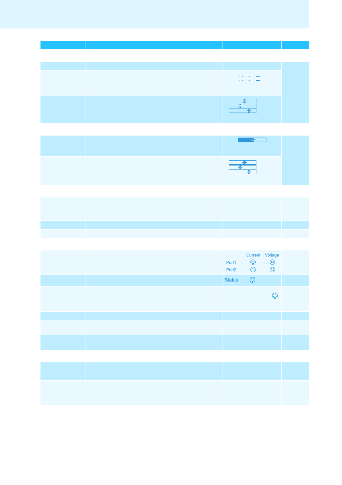
connections PORT I or PORT II – “Ports”
The “Ports” menu item displays the number of delegate units (“Deleg”) and
chairman units (“Chair.”) connected to the connection sockets PORT I and PORT II.
37
Page 39

Configuring the conference system via the central unit
Select and call up the
“System” submenu
Select and call up the
“Diagnostics” submenu
The “Diagnostics”
submenu appears
Main Menu
Conference
Audio
System
System
Ports
Diagnostics
Versions
System Load
Temperature
Bus Statistics
Diagnostics
No No
Select and call up the
“Diagnostics” submenu
Select and call up the
“Load” menu item
View the information;
exit the menu item
Diagnostics
System Load
Temperature
Bus Statistics
Load
No No
Main Menu
System
Diagnostics
Current Voltage
Port 1 ☺
Port 2 – –
System analysis – “Diagnostics” submenu
The “Diagnostics” menu item provides information on the status of the current and
voltage supply, on the status of data transmission and on interruptions due to
faulty cables or cable connections.
Displaying status information on the
current and
voltage supply –
“System Load”
Both ports can be subjected to undervol
tages, overcurrents and short-circuits:
Display Meaning and causes
Current An overcurrent in the central unit can be caused by
• metal parts (e.g. paper clips) that bridge the contacts of the plug
connections
• faulty conference units
• faulty system cables
• too long system cables
• too many conference units connected to one port
Voltage An undervoltage can be caused by
• faulty conference units
• too long system cables
• too many conference units connected to one port
Current A short-circuit in the central unit can be caused by e.g.
• metal parts (e.g. paper clips) that bridge the contacts of the plug
connections
• faulty system cables
• wrong cables (e.g. crossover cables)
Voltage --The port is deactivated due to e.g.
• no conference units connected
• a short-circuit
38
If an error icon appears (see page 34), check your conference system for the errors
mentioned above.
If an error is detected at startup of the central unit, first eliminate the
error and then perform a manual self-test (see page 40) in order to check
if the error still occurs.
If an error has only occured during operation and has already been elim-
inated, this is automatically detected by the central unit.
Possible steps for error elimination:
• Eliminate the errors separately for each port.
• Calculate the maximum length of the cable string (see page 13) and, if necessary, reduce the cable length.
• Reduce the number of conference units to 15-20
max. per cable string.
Page 40

Displaying the temperature status –
Select and call up the
“Diagnostics” submenu
Select and call up
the “Temperature”
menu item
View the information;
exit the menu item
Diagnostics
System Load
Temperature
Bus Statistics
Temperature
No No
Main Menu
System
Diagnostics
Status ☺
☺
N☺N
em
perature”
“T
Configuring the conference system via the central unit
• If necessary, further reduce the number of conference units until there are no
errors reported.
Then add conference units one after
the other and observe the central unit’s
display. If an error is reported, the cause of the error might be the last added
conference unit, the cable used or metal parts that bridge the contacts of the
plug connection.
Displaying system bus errors –
Statistics”
“Bus
If the temperature within the central u
nit is too high (display: “ ”), proceed as
follows:
왘 Make sure that the air vents are not covered or blocked (see page 15).
왘 If necessary, clean the air vents (see page 104).
If the central unit is mounted into a rack:
왘 Provide additional ventilation by providing for a clearance below the central
and/or installing additional fans into the rack.
t
uni
When the temperature is again within the
permissible temperature range, this
is automatically detected by the central unit (display: “ ”). The temperature
check is carried out cyclically.
If, in spite of these measures, the temperature is still detected to be too high, one
of the fans might de faulty:
왘 Have the fans checked and, if necessary, replaced by qualified maintenance
rso
nnel.
pe
Main Menu
System
Diagnostics
Select and call up the
“Diagnostics” submenu
Diagnostics
Load
Temperature
Bus Statistics
Select and call up
the “Bus Statistics”
menu item
No No
Bus Statistics
Error Indication : ☺
Break Counter : 1
View the information;
exit the menu item
Possible causes for system bus errors are:
• changes in the number of conference units
• faulty cables
• faults in cable shields
• faulty conference units
• strong electromagnetic fields
If there are system bus errors, the “ ” icon appears behind “Error Indication”.
The display panel lights up red and the warning triangle is displayed on the
standard display (see page 34).
There are temporary or permanent transmission errors:
Temporary transmission errors can be caused by e.g. poorly shielded mobiles
phones that
are placed too close to the system cables or conference units. If the
transmission error no longer exists, the “ ” icon appears on the display. The
display panel lights up orange and the warning triangle goes off.
39
Page 41

Configuring the conference system via the central unit
☺
Select and call up the
“Diagnostics” submenu
Select and call up the
“Reset Break Indication”
menu item
Select the desired
setting; apply the setting
Diagnostics
Bus Statistics
Start Self Test
Reset Break Indication
Reset Break Indication
Main Menu
System
Diagnostics
Yes
No
Select and call up the
“Diagnostics” submenu
Select and call up
the “Reset Error
Indication” menu item
Select the desired
setting; apply the
setting
Diagnostics
Start Self Test
Reset Break indication
Reset Error Indication
Reset Error Indication
Main Menu
System
Diagnostics
Yes
No
Permanent transmission errors must be eliminated immediately in order to ensure
trouble-free operation of your conference system. Follow the steps for error elimination described under the “System Load” menu item (see page 38). In addition,
check if other electronic devices in the proxim
cause the errors.
You can manually reset the “ ” icon behind “Error Indication” to the default icon
(“ ”) (see page 40).
The error counter (“Break Counter”) incrementally counts all
the conference system (e.g. added conference units). Based on the changes of the
counter’s counts, you can conclude on the error source (e.g. if the counter rapidly
increments when you wiggle the cable, this indicates a faulty cable).
You can manually reset the error counter (“Break Counter”) (see page 40).
ity of the conference system might
errors an
d changes in
Performing a manual self-test –
Start Self-Test”
“
Resetting the error counter –
“Reset Break Indication”
Diagnostics
Main Menu
System
Diagnostics
Select and call up the
“Diagnostics” submenu
Temperature
Bus Statistics
Start Self-Test
Select and call up
the “Start Self-Test”
menu item
If the central unit detects errors after swi
No No
tch-on or during operation:
Start Self-Test
Yes
No
Start Self-Test
Select the desired
setting; apply the
setting
왘 Eliminate these errors (see page 34 and following).
왘 Perform a manual self-t
est by selectin
g “Yes” in the “Start Self-Test” menu
item. The conference is interrupted.
The central unit now checks if a reported error still occurs. If the error is eliminated, the corresponding error icon goes off after the self-test. If the err
icon is still displayed, you have to take further steps to eliminate the error
(see page 34 and following).
Always perform the self-test after you have eliminated the reported
errors.
or
40
Resetting the display of
ta bus errors –
a
d
“Reset Error Indication”
Possible settings: “Yes” or “No”
This menu item allows you to reset the error counter (“Break Count”) in the “Bus
Statistic” menu item (see page 39).
Possible settings: “Yes” or “No”
This menu item allows you to manually reset the display of data bus errors (“Error
Indication”) in the “Bus Statistic” menu item to default (see page 39).
Page 42

Configuring the conference system via the central unit
We strongly recommend to always perform a self-test (see page 40) in
order to make sure that the error is eliminated.
After a successful self-test, the error icons go off and the display of data
bus errors is automatically reset to default.
Displaying the hardware and software version – “Versions” submenu
Displaying the hardware version –
“Hardware V
ersion Info”
Displaying the software version –
“Software Version Info”
Main Menu
Conference
Audio
System
Select and call up the
“System” submenu
System
Ports
Diagnostics
Versions
Select and call up the
“Versions” submenu
Versions
Hardware Version Info
Software Version Info
No No
The “Versions”
submenu appears
The “Versions” menu item provides information on your hardware and software
versions.
e
Information on firmware updat
s for your conference system is available from
your Sennheiser partner or from the download area on our website at
www.sennheiser.com.
Main Menu
System
Versions
Select and call up the
“Versions” submenu
Main Menu
System
Versions
Select and call up the
“Versions” submenu
Versions
Hardware Version Info
Software Version Info
Select and call up
the “Hardware Version
Info” menu item
Versions
Hardware Version Info
Software Version Info
Select and call up
the “Software Version
Info” menu item
No No
No No
Hardware Version Info
DU/PU: 1
CU SB: 1
View the information;
exit the menu item
Software Version Info
DU/PU: 0.1.1.5
CU SB: 1.0.0.0
CU Main: 1.0.0.0
View the information;
exit the menu item
Adjusting the language – “Language”
Via the “Language” menu item, you can adjust the language of the operating
menu:
Main Menu
Audio
System
▪
Languages
English
Select and call up the
“Language” menu item
Language
English
Deutsch
Nederlands
Select the desired
setting; store the
setting
No
41
Page 43

Configuring the conference system via the central unit
Select and call up the
“Settings” submenu
Select and call up the
“Network” submenu
The “Network” submenu
appears
Main Menu
System
Languages
Settings
Settings
Network
Contrast
Lock
Network
IP Adress Mode
IP Address
Subnet Mask
No Static IP
Select and call up the
“Network” submenu
Select and call up
the “IP Address Mode”
menu item
Select the desired
setting;
store the setting
Network
IP Address Mode
IP Address
Subnet Mask
Static IP Static IP
IP Address Mode
Static IP
Dynamic IP
Main Menu
Settings
Network
Adjusting further settings – “Settings”
Adjusting network settings – “Network” submenu
The “Network” submenu allows you to set the IP address allocation mode, the IP
address and the subnet mask.
For detailed information on network settings, refer to the chapter “Preparing the
Windows version of the software for use” on page 50.
Setting the IP address allocation
e
– “IP Address Mode”
mod
Setting a static IP address –
“IP Address”
Setting a static subnet mask –
“Subnet Mask”
Possible settings: “Static IP” and “Dynamic IP”
By selecting “Static IP”, you gain access to the “IP Address” and “Subnet
Mask” submenus (see the following sections).
Network
Main Menu
Settings
Network
Select and call up the
“Network” submenu
Main Menu
Settings
Network
Select and call up the
“Network” submenu
IP Mode
IP Address
Subnet Mask
10.49.68.179 10.49.68.179
Select and call up the
“IP Address” menu item
Network
IP Mode
IP Address
Subnet Mask
255.255.0.0 255.255.0.0
Select and call up
the “Subnet Mask”
menu item
Adjusting the contrast of the display panel – “Contrast”
Main Menu
System
Languages
Settings
Select and call up the
“Settings” submenu
Settings
Network
Contrast
Lock
Select and call up the
“Contrast” menu item
09 09
IP Address
10 . 49 . 68 . 179
Select the desired
setting; store the
setting
Subnet Mask
255 . 255 . 0 . 0
Select the desired
setting; store the
setting
Contrast
10
Select the desired
setting; store the
setting
42
You can adjust the contrast of the display panel in 15 steps.
Page 44

Configuring the conference system via the central unit
Activating the lock mode – “Lock”
Main Menu
System
Languages
Settings
Select and call up the
“Settings” submenu
Settings
Network
Contrast
Lock
Select and call up the
“Lock” menu item
Lock
On
Off
Select the desired
setting; store the
setting
When you activate the lock mode, you are automatically returned to the standard
display. For information on how to deactivate the lock mode, refer to page 21.
Restoring the factory default settings – “Restore Factory Default
Main Menu
System
Languages
Settings
Select and call up the
“Settings” submenu
Settings
Contrast
Lock
Restore Factory Defaults
Select and call up the
“Restore Factory
Defaults” menu item
s”
Restore Factory Defaults
Yes
No
Select the desired
setting; apply the
setting
The “Restore Factory Defaults” menu item allows you to restore the factory default
settings (see “Factory default settings” on page 111).
43
Page 45

Running a conference
Running a conference
The character of your conference (i.e. the conditions under which the participants
can take the floor or are granted speaking privileges) depends on the settings of
the central unit (see page 26).
Possible settings: “Direct Access”, “Override” and “Request”.
•“Direct Access” mode and “Override” mode:
r
These two conference modes do not requi
If the maximum number of speakers who can take the fl
(“Microphone Limit”) has not been reached, a further speaker can take the
floor immediately.
Situation The maximum number of speakers who can take the floor
simultaneously (“Microphone Limit”) has been reached.
Event A further speaker presses the microphone key on his or her
conference unit.
Behavior In “Direct Access” mode:
The speaker has to wait until one of the current speakers passes
on or loses his or her speaking privileges. He or she is then automatically granted speaking privileges.
In “Override” mode:
The speaker can take the floor immediately. The speaker with
the longest speaking time loses his or her speaking privileges.
e the use of a chairman unit.
oor simultaneously
•“Request” mode:
For this mode to function, a chairman unit is required.
In “Request” mode, the chairman receives requests to speak an
speaking privileges according to the FIFO principle (First In – First Out), i.e. the
speaker with the longest waiting time is granted speaking privileges.
Situation The maximum number of requests to speak has been reached
(“Request Limit”).
Event A further speaker makes a request to speak.
Behavior The speaker can only make a request to speak if the maximum
number of requests to speak drops below the specified limit
value.
You can control the conference either via chairman units (see the
following chapters) or via the “Conference Manager” software (see
page 49).
d gra
nts
44
Page 46

Operating a delegate unit
Taking the floor/Making a request to speak
Depending on the conference mode set (see page 26) you can
• take the floor immediately or
• make a request to speak.
Running a conference
You then have to wait until the chai
If the conference mode is set so that you can take the floor immediately (“Direct
Access” mode (factory default setting) or “Override” mode, see page 26):
왘 Press the microphone key .
Your microphone is activated and you ca
The microphone LED and the signal light ring light up red. The
loudspeaker is muted. Depending on the conference mode and the microphone limit set, the microphone of the prev
If the conference mode is set so that you firs
(“Request” mode, see page 26):
왘 Press the microphone key .
Your request to speak is added to t
Depending on the setting adjusted in the operating
– the microphone LED flashes green and the signal light ring flashes red
or
– only the microphone LED flashes green.
When the chairman grants you speaking privileges, your micr
vated. The microphone LED and the signal light ring light up red. The
loudspeaker is muted. Depending on the conference mode and the microphone limit set, the microphone of the prev
With a chairman unit, you can take the floor at any time, without first
having to be granted speaking privileges.
If you are using delegate units only, you can only choose conference
modes where speaking privileges do not have to be granted by a
chairman (“Direct Access” or “Override” mode, see page 26). Alternatively, you can use the “Conference Mana
delegate units (see page 95).
activates your microphone.
rman
n take the floor immediately.
ious speaker will be deactivated.
t have to make a request to speak
he request-to-speak list.
menu (see page 30):
ious speaker will be deactivated.
ger” software to control the
ophone is acti-
Deactivating the microphone/Cancelling
To deactivate the microphone when you have finished speaking or to cancel a
request to speak:
왘 Press the microphone key once more.
The microphone LED and the signal light ring go off.
a request to speak
45
Page 47

Running a conference
쐋
Connecting headphones
You can connect mono or stereo headphones to the
conference unit to listen to the
floor channel. The headphone volume can be individually adjusted on the conference unit.
왘 Connect headphones with a 3.5 mm jack plug to the headphone socket .
Setting the headphone volume
CAUTION Hearing damage due to high volumes!
Listening at high volume levels for long period
s can lead to perma-
nent hearing defects.
왘 Inform the conference participants about this fact.
왘 Set the volume to a medium level.
and
왘 Do not continuously expose yourself
other conference partic-
ipants to high volumes.
왘 Put the headphones on.
To set the volume:
왘 Turn the headphone volume control
– to the right to increase the volume or
– to the left to reduce the volume.
At switch-off, the headphone volume
is reset to a medium level.
The volume of the conference units’ loudspeakers can be set via the
central unit (see page 48).
Vol -
Vol +
Operating a chairman unit
Beside the chairman functions, chairman units offer the same functions as delegate units (see page 45).
With a chairman unit, you can take the floor at any time.
If your conference system comprises several chairman units, all chairman
units have equal rights.
46
Page 48

Running a conference
Granting speaking privileges
If – in “Request” mode – a participant presses the mic
delegate unit, he or she makes a request to speak. All participants who have made
a request to speak will join a request-to-speak list.
Depending on the setting adjusted in the operating menu (see page 30):
• the microphone LED flashes green and the signal light ring flashes red or
• only the microphone LED flashes green.
To grant speaking privileges to the next participant from the request-to-speak list:
왘 Press the NEXT key .
The next participant from the request-to-speak list is granted speaking privileges.
rophone key on his or her
If you are using the “Conference Manager” software, you can also
grant speaking privileges with a mouse click (see page 99).
Ending a conference or withdrawing speaking privileges (cancel function)
Depending on the setting adjusted in the operating menu (see page 30):
• All LEDs go off and the delegate units ar
if available, is cleared.
• All currently active delegate units are deactivat
retained.
왘 Briefly press the priority key .
The conference system behaves as set.
If you are using the “Conference Manager” software, you can also
deactivate all delegate units with a mouse click (see page 95).
e deactivated. A request-to-speak list,
ed. All requests to speak are
47
Page 49

Running a conference
H
Muting all delegate units temporarily (priority function)
Using the priority function, the chairman can interrupt a di
The speaking privileges of all chairman units remain active at any time.
왘 Keep the priority key pressed for as long as you want to mute the confer-
ence units.
All conference units – except for the chairman units – are muted immediately.
The microphone LED and the signal light ring of the previously active
conference units flash red. You can take the fl
LED and the signal light ring of your chairman unit light up red.
왘 Release the priority key .
u
The muting of the conference
nits is canceled. The discussion is continued.
oor immediately. The microphone
scussion at any time.
Setting the volume of the conference units’ built-in loudspeakers
Direct Access
20
Units: 30
N
You can set the volume of the conference units’ built-in loudspeakers via the jog
dial on the central unit. The standard display displays the current volume
setting.
CAUTION Danger of hearing damage due to loud hissing!
When the floor channel volume is set to a hig
participants speak simultaneously, feedback noise (loud hissing) can
occur. This can cause hearing damage.
왘 Reduce the floor channel volume (see page 48, page 93 or
page 101).
왘 Make sure that the “Audio Gain Reduction” function is activated
(see page 32). This function reduces the gain per active microphone by the selected level and thus
왘 Increase the distance between the indi
at least 50 cm.
왘 Turn the jog dial
to the right to increase the volume or
–
– to the left to reduce the volume.
The volume of the conference units’ loudspeakers can also be set via
the central unit’s operating menu (see page 32) or the “Conference
Manager” software (see page 93).
h level or when several
prevents feedback noise.
vidual conference units to
48
Adding conference units to the conference system during operation
You can add conference units to the conference system during operation.
When adding conference units to the conference
maximum number of conference units in order to ensure safe operation
(see page 13).
All delegate units are ready for immediate use. The chairman units have to be
re-initialized. Note that this will interrupt the conference (see page 30 or page 88).
system, observe the
Page 50

Using the “Conference Manager” software
Using the “Conference Manager”
software
Possibilities of usage of the software and the conference system
The “Conference Manager” software allows you to conveniently manage and
control the conference system. With the software, you can plan and graphically
simulate conferences. Various configurations can be saved and thus be reused for
other scenarios. In addition, you can use the software to control conferences.
Conference rooms and conference participants are represented graphically,
allowing you to keep track of and securely manage your conferences.
Hardware platforms for the software
The “Conference Manager” software can be run in two different ways:
Using the software preinstalled on
t
the cen
Using the software on a Windows PC Alternatively, you can install the software on a Windows PC.
ral unit
The software is preinstalled on the central unit. In order to be able to use the
software, you have to connect a screen, mouse and keyboard directly to the central
unit (see “Preparing the central unit’s integra
grate the PC together with the central
Windows version of the software for use” on page 50).
ted software for use” on page 50).
unit in a network (see “Preparing the
You then have to inte-
Planning and
lating conferences –
simu
“Setup” operating mode
Controlling conferences via the
tware – “Live” operating mode
sof
“Setup” and “Live” operating mode
In “Setup” operating mode, you can plan, configure and simulate conference situations. The software allows you to easily plan your conference by simulating a
conference room, e.g. using lines, colors and photos. You can realistically simulate
room situations, manage the names of the conference participants and assign
these names to individual conference units. All conference settings can be adjusted
and saved via the “Conference Manager” software. These settings can then be used
in “Live” operating mode.
In “Live” operating mode, you can control a conference from your screen. For
controlling the conference, you can choose between two views: “Room View” and
“Delegate View”. You can see at a glance which delegates are currently speaking
and which have made a request to speak and you can activate or deactivate individual conference units just with a mouse click.
o
Establishing a connection between the s
In order to be able to control a conference via
you have to connect the software to the conference system. If you are using a
networked Windows PC, you can select different central units in the network. The
software preinstalled on a central unit can only be connected to its central unit.
If you want to preconfigure a conference system, you
Manager” software if there is no connection to the central unit.
ftware and the conference system
the “Conference Manager” software,
can
also use the “Conference
49
Page 51

Using the “Conference Manager” software
“Disconnected”
– not connected
to the central unit
“Setup” operating mode
• Room View window
can be edited
• Delegate View
window can be
edited
• Configuration can
be edited
“Setup” operating mode
• Room View window
can be edited
• Delegate View
window can be
edited
• Configuration can
be edited
• Conference units
can be initialized
“Live” operating mode
• Conference control
via Room View
window
• Conference control
via Delegate View
window
• Configuration
can be edited
“Connected”
– connected to the central unit
The following overview shows the functions that are available depending on the
connections status:
Preparing the central unit’s integrated software for use
Connecting and configuring the screen, mouse, and keyboard
왘 Connect the screen, mouse, and keyboard to the
To optimally use the screen, mouse, and keyboard, you have
devices one time:
왘 Adjust the setting for the screen, mouse, a
page 63).
Preparing the Windows version of the software for use
System requirements
Component Requirement
Processor Intel Pentium 4 or AMD Athlon XP, 2 GHz or more
RAM Min. 512 MB
Hard disk Min. 150 MB free hard disk memory
Drives CD ROM or DVD ROM
Interfaces/network Ethernet 100 MBit/s
TCP/IP internet protocol Internet Protocol version 4 (IPv4)
Screen Minimum resolution: 800 x 600 pixels
Operating system Microsoft Windows XP Professional with SP 2
central unit (see page 19).
n
d keyboard to your needs (see
Recommended: 1024 x 768 pixels
Microsoft Windows Vista
Microsoft Windows 7
to configure the
50
Page 52

Using the “Conference Manager” software
Installing the “Conference Manager” software
왘 Start the “ADNSetup.exe” file in the “Conference Manager” folder on the
enclosed CD ROM.
A c
onfirmation prompt appears:
왘 Click the “Next” button.
A selection window appears:
왘 Make sure that the “ADN Conference Manager (local)” check box is ticked.
왘 Click the “Next” button.
A summary of the installation settings is displayed:
왘 Confirm this summary by clicking the “Install” button.
The installation starts.
왘 Follow the instructions of the Installation Wizard.
51
Page 53

Using the “Conference Manager” software
Adjusting the network settings To enable communication between the central unit and the Windows PC:
왘 Make sure that the network communication between the central unit and
Windows PC is not blocked by a proxy server and/or a firewall.
Ports 53248, 53249, 53250, 53251 are used for commun
used for FTP transfer.
왘 Ask your system administrator if a static IP address is to be used or if the IP
dress is to be allocated dynamically.
ad
If you have to use a static IP address, as
gateway.
왘 Use the information provided by your system administ
network settings of your central unit. Proceed as described under b) in the
table on page 54.
k for the subnet mask and the standard
the
ication and port 21 is
rator to adjust the
If you have to make the decision whether to
proceed as follows:
If the central unit is directly connected to a Windows PC, we recommend
dynamic IP address allocation. Adjust the network settings of the PC and
the central unit as described under a) in the table on page 53.
The devices automatically detect whether IP add
DHCP or Zero Configuration Networking (Zeroconf). This process can take
several minutes.
Windows XP Windows Vista Windows 7
왘 Click “Start” and then select “Control Panel”.
use static or dynamic IP addressing,
r
ess allocation is via
The “Control Panel” window appears.
왘 Double click “Network and Internet
Connections”:
The “Network and Internet connec-
tions” window appears.
52
왘 Click “View network status and
tasks”:
The “Network and Sharing Center”
window appears.
왘 Click “View network status and
tasks”:
The “Network and Sharing Center”
window appears.
Page 54

Using the “Conference Manager” software
Windows XP Windows Vista Windows 7
왘 Click “Network Connections” in the
right column:
왘 Click “Manage network connec-
tions” in the left column:
왘 Click “Change adapter settings” in
the left column:
The “Network Connections” window
appears.
왘 Double-click “Local Area Connec-
tion”:
The “Local Area Connection Status”
window appears.
왘 Click the “Properties” button:
The “Network Connections” window
appears.
왘 Double-click “Local Area Connec-
tion”:
The “Local Area Connection Status”
window appears.
왘 Click the “Properties” button:
The “Network Connections” window
appears.
왘 Double-click “Local Area Connec-
tion”:
The “Local Area Connection Proper-
ties” window appears.
왘 Click the “Properties” button:
The “Local Area Connection Proper-
ties” window appears.
왘 In the “This connection uses the
following items” box, scroll to the
bottom.
왘 Double-click “Internet Protocol
(TCP/IP)”.
The “Internet Protocol (TCP/IP) Properties” window appears.
Here you can see whether the Windows PC is assig ned a st atic or dynami c IP addres s. Adju st your centra l unit a s fo llows:
a) The Windows PC is assigned a dynamic IP address in the network:
The “Local Area Connection Proper-
ties” window appears.
왘 In the “This connection uses the
following items” box, double-click
“Internet Protocol Version 4 (TCP/
IPv4)”.
The “Local Area Connection Proper-
ties” window appears.
왘 In the “This connection uses the
following items” box, double-click
“Internet Protocol Version 4 (TCP/
IPv4)”.
53
Page 55

Using the “Conference Manager” software
Windows XP Windows Vista Windows 7
Settings to be adjusted via the central unit (see page 42):
Main Menu
Settings
Network
IP Mode
왘 On the central unit, call up the “IP Mode” menu item.
왘 Select “Dynamic IP”.
The central unit is automatically integrated in the network and no further steps have to be taken.
b) The Windows PC is assigned a static IP address in the network:
Settings to be adjusted via the central unit (see page 42):
왘 On the central unit, call up the “IP Mode” menu item.
Main Menu
Settings
Network
IP Mode
왘 Select “Static IP”.
왘 Determine the network part of the IP address of the Windows PC and note it down:
network part
192 . 168 . 1 . 145
device part
In this example, the network part is “192.168.1”.
왘 On the central unit, call up the “IP-Address” menu item:
Main Menu
Settings
Network
IP Address
왘 Set the network part of the IP address to the value retrieved from your Windows PC.
왘 Set the device part (the last three digits) of the IP address to a value (“1” - “254”) that is neither used by your PC nor
by another computer in your network (in this example, the device part must not be “145”).
54
Page 56

Using the “Conference Manager” software
Starting/exiting the software
The central unit’s integrated software
To start the central unit’s integrated software:
왘 Switch on the central unit and the connected screen.
The “Conference Manager” software is started in
the Room View window is displayed. The “Open” window appears in the foreground.
If the screen connected to the central unit does not show anything, it may
be that the screen resolution is set too high. In this case, reset the screen
resolution:
왘 Press the key combination “CTRL” + “SHIFT” + “F1”.
The screen resolution is reset to 800 x 600 pixels.
To exit the software:
왘 If necessary, save your current configuration (see page 69).
왘 Switch off the central unit.
The Windows version of the software
To start the software:
왘 Double-click the program icon on the desktop.
Or:
왘 Click “Start” > “All Programs” > “Sennheiser” > “ADN” > “SENNHEISER
ence Manag
Confer
The “Conference Manager” software is started in
the Room View window is displayed. The “Open” window appears in the foreground.
To exit the software:
왘 If necessary, save your current configuration (see page 69).
왘 Click the button on the toolbar.
er”.
“Setup” operating mode and
“Setup” operating mode and
55
Page 57

Using the “Conference Manager” software
abc
d
e
f
Getting to know and adjusting the basic features of the software
Overview of the software
The main application window of the “Conference Manager” software consists of
permanently visible elements and on views that depend on the operating mode.
The following diagram shows the Windows version of the “Conference Manager”
tware:
sof
f
a
e
b
c
d
Menu bar
Buttons for selecting the views
Toolbar
Library panels
Buttons for selecting the operating
Views
mode
56
Page 58

Using the “Conference Manager” software
a
Menu bar
Menu Submenu Function Page
Global Menu New
Creates a new configuration 67
Conference
Open
Loads an existing configuration 68
Conference ...
Delete
Deletes and existing configuration 71
Conference
Close Closes the current configuration 70
Save Saves the current configuration
69
(locally or on the central unit)
Save as ... Saves the current configuration under
a different file name
(locally or on the central unit)
Connect/
Disconnect
Autoload ... Automatically loads the central unit’s
Establishes a connection to the central
unit/disconnects a connection
66
69
configuration at startup
Exit
*
Exits the software 55
Edit Undo Reverses the last action you performed 81
Redo Reverses the last Undo action
Cut Cuts an object and pastes it to the
81
clipboard
Copy Copies an object to the clipboard
Paste Pastes an object from the clipboard
Delete Deletes an object
Step to back Moves the object one level to the back 81
Step to front Moves the object one level to the front
Select All Selects all objects 76
Full Screen* Activates/deactivates full screen mode 63
Settings Conference
Settings
Audio
Opens the conference settings 90
...
Opens the audio settings 93
Settings ...
Language Adjusts the language 64
Set
Sets the password protection 64
Password ...
Network Opens the network settings 65
Re-init
Re-initializes the conference units 88
Conference
Restore
Factory
Restores the factory default settings of
the software
65
Settings
System
Properties
Opens the hardware settings for screen,
**
mouse and keyboard
63
Help Help ... Starts the help function –
About ... Displays the current software version –
* only visible when you are using the Windows version of the software
** only visible when you are using the central unit’s integrated software
57
Page 59

Using the “Conference Manager” software
b
c
e
Alternatively, you can also use the keyboard shortcuts listed next to the
commands.
Buttons for selecting the views
Button Function
Changes to the Room View window where you can
configure and/or control the conference system via a
graphical interface.
The Room View window changes depending on whether
“Setup” or “Live” operating mode is set (see page 59).
Changes to the Delegate View window where you can create
a delegate list and control the conference by means of the
list.
The Delegate View window changes depending on whether
“Setup” or “Live” operating mode is set (see page 59).
Toolbar
Button Function
Opens the “Audio Settings” window (see page 93)
Opens the “Conference Settings” window (see page 90)
Displays the status of the central unit’s lock mode
(see page 93)
“Device Unlocked”
“Device Locked”
Displays the connection status between the central unit and
the “Conference Manager” software (see page 66)
“Device Unconnected”
“Device Connected”
Displays detected errors and opens the event log
(see page 102)
“Event Log”
“Errors detected
*
* only available in the Windows version of the software
Closes the software (“Exit”) (see page 55)
”
Buttons for selecting the operating mode
Button Function
Sets the “Setup” operating mode which allows you to
configure the conference system (see page 60).
The button is highlighted in blue. The Room View window
and the Delegate View window change their appearance in
accordance with the selected operating mode.
Sets the “Live” operating mode which allows you to control
a conference using the software (see page 61).
The button is highlighted in re
and the Delegate View window change their appearance in
accordance with the selected operating mode.
d. The Room View window
58
Page 60

Selecting operating modes and views
In “Setup” and “Live” operating mode, you can switch
window and the Delegate View window.
Views of the software depending on the operating mode
Using the “Conference Manager” software
between the Room View
“Setup” operating mode
Button for selecting the
“Setup” operating mode
“Live” operating mode
Button for selecting the
“Live” operating mode
View buttons View buttons
Room View window Delegate View window Room View window Delegate View window
59
Page 61

Using the “Conference Manager” software
Selecting the
“Setup” operating mode
왘 Click the “Setup” button.
The software changes to “Setup” operating mode and the “Setup” button is
highlighted in blue.
To display the Room View window:
왘 Click the Room View button .
To display the Delegate View window:
왘 Click the Delegate View button .
60
Page 62

Using the “Conference Manager” software
Selecting the “Live” operating mode 왘 Prepare the “Live” operating mode and activate it (see page 95).
To display the Room View window:
왘 Click the Room View button .
To display the Delegate View window:
왘 Click the Delegate View button .
61
Page 63

Using the “Conference Manager” software
Hiding, showing and resizing
the library panels
Adjusting the Room View window and the Delegate View window to your needs
You can adjust the Room View window and the Delegate View window to your
ne
eds. The library panels can be hidden or shown and can be changed in size.
Changes to the View windows are not automatically saved and are reset to the
factory default settings when the software is exited.
Library panels that show the or icon can be minimized and maximized:
The header of a library panel is always displayed.
Adjusting the column width of the
delegate list
To hide a library panel:
왘 Click the or icon in the header of the library panel that you want to hide.
To show a library panel:
왘 Click the or icon in the header of the library
To change the size of a library panel:
왘 Move over the or icon between the library panels.
The mouse pointer becomes the resize tool .
br
왘 Adjust the size of the li
The and the icons display if the “Equipment”, “Images” or
“Microphone Unit(s)” library panel is locked ( ) or unlocked ( )
(see page 84).
To change the column width of the delegate list:
왘 Move the mouse pointer over the head
The mouse pointer becomes the resize tool .
왘 Adjust the column width as needed.
ary panel as needed.
er of the delegate list.
panel that
you want to show.
62
A double-click automatically adjusts the column width to fit the contents.
Page 64

Using the “Conference Manager” software
Using the full screen mode of the
Windows software
왘 In the menu bar, click “Edit” > “Full Screen”.
The full screen mode of the software is activated/deactivated.
Adjusting the screen, mouse, and keyboard settings
the central unit
*
and the date/time setting of
왘 In the menu bar, click “Settings” > “System Properties”.
The “System Properties” window appears.
To adjust the screen settings:
왘 Select the desired value from the drop-down list in the “Screen Resolution”
box.
The screen resolution should be at least 800 x 600 pi
xels (recommended:
1024 x 762 or 1280 x 1024 pixels).
Screen resolutions and refresh rates are automatically adapted to the
connected screen so that you can always select the optimum settings for
e.g. flat screen monitors or video projectors. It might be necessary to
restart the central unit in order to be able to select the optimum settings
for your screen.
If the screen connected to the central unit
does not show anything, it may be that
the screen resolution is set too high. In this case, reset the screen resolution:
왘 Press the key combination “CTRL” + “SHIFT” + “F1”.
The screen resolution is reset to 800 x 600 pixels.
To adjust the mouse pointer
speed:
왘 In the “Mouse Speed” box, move the slider to
–“Slow” to reduce the pointer speed or to
–“Fast” to increase the pointer speed.
To adjust to keyboard layout to the central unit (e.
. cyrillic keyboard layout):
g
왘 Select the desired value from the drop-down list in the “Keyboard Layout” box.
To adjust the date and time of the central unit:
왘 Highlight the individual digits in the “Local Time” box.
왘 Enter the date and time via the keyboard or click the buttons to increase or
reduce the highlighted digits.
왘 Click “OK”.
The settings are saved and the “System Properties” windows closes.
* only if you are using the central unit’s integrated software
63
Page 65

Using the “Conference Manager” software
Protecting configurations with a
password and changing a password
The “Disk Space” box in the “System Properties” window provides information on the free memory available on the central unit.
Selecting the language
왘 In the menu bar, click “Settings” > “Language”.
A list with the available languages appears.
왘 Click the desired language.
The language of the software is changed.
Using a password
You can use a password to protect existing configurations against unauthorized
change. This means that all settings adjusted in “Setup” operating mode are
locked. However, password-protected configurations can be used in “Live” mode
and settings can be adjusted.
왘 In the menu bar, click “Settings” > “Set Password...”.
The “Set Password” window appears.
To enter a new password:
왘 Leave the “Old Password” field empty.
To change an existing password:
왘 Enter the existing password into the “Old Password” field.
왘 Enter the new password into the “New Password” and “Confirm new Password”
ds.
fiel
e password can consist of up to 16 characters.
Th
If you do not want to use a password, leave the “New Password” and
“Confirm new Password” fields empty.
왘 Click “OK”.
The new password is saved and the configuration i
Before any changes to the configuration are accepted, you are prompted to
enter the password set.
The master key combinatio
configurations:
왘 Press the key combination “CTRL” + “SHIFT” + “F10”.
An existing password is deleted.
n allows you to unlock password-protected
s password-protected.
64
Page 66

Using the “Conference Manager” software
Adjusting network settings
If you make changes to the settings in the “Network Settings” window,
an existing network connection can be lost!
왘 In the menu bar, click “Settings” > “Network...”.
The “Network Settings” window appears.
To automatically integrate the central unit in a network using a dynamic IP address:
왘 Select the “Obtain an IP Address automatically” option button.
왘 Click “OK”.
The setting is applied and the “IP Address” and “Subnet mask” fields display
he automatically assigned addresses.
t
To manually integrate the central unit in a n
왘 Select the “Use the following IP Address” option button.
왘 Enter the desired IP address into the “IP address” field.
왘 Enter the desired subnet mask address into the“Subnet mask” field.
etwork using a static IP address:
왘 Click “OK”.
The setting is applied.
For further information on the network conf
system, refer to page 52.
Loading the factory default settings
왘 In the menu bar, click “Settings” > “Restore Factory Settings”.
All software settings are reset to default.
If the screen connected to the central unit does not show an
be that the screen resolution is set too high. In this case, reset the screen
resolution:
왘 Press the key combination “CTRL” + “SHIFT” + “F1”.
The screen resolution is reset to 800 x 600 pixels.
iguration of the conference
ything, it may
65
Page 67

Using the “Conference Manager” software
Using the conference system and the software
Connecting the software to the central unit
To connect the “Conference Manager” software to the
왘 Start the software (see page 55).
The “Open” window appears.
왘 Click “Connect”.
Or:
왘 In the menu bar, click “Global Menu” > “Connect ...”.
The “Connect to CU” window appears, showing a list of avail
central unit:
abl
e central units.
왘 Select the desired central unit.
•The “Connect” button is also available in other program windows. Its
function i
the central unit.
• The Windows version of the software allows you to select different
central units in the network. The central unit’s integrated software
can only be connected to its own central unit.
왘 Click “OK”.
The software is connected to the selected central unit. The “Device Connected”
icon appears on the toolbar.
s always to connect the “Conference Manager” software to
66
Page 68

Using the “Conference Manager” software
Eliminating connection problems
If no connection to the central unit can be establis
hed or if the configuration cannot
be found, an error message appears.
왘 Check if the central unit is correctly connected* (see page 50) and switched on
(see page 20).
왘 If necessary, disconnect an existing connecti
on to the central unit in order to
establish a new connection (see next section).
왘 Click “Retry”.
Disconnecting the connection to the central unit
왘 In the menu bar, click “Global Menu” > “Disconnect”.
A confirmation prompt appears.
왘 Click “OK”.
The connection to the central unit is disconnected. If necessary, the software
changes to “Setup”
operating
mode.
Creating a new configuration
왘 In the menu bar, click “Global Menu” > “New Conference Document”.
The “Open” window appears.
왘 Select the “New Conference Document” option button.
왘 Click “OK”.
A new configuration is created. The software changes t
o “Setup” operating
mode and the Room View window is displayed (see page 60).
* only if you are using the Windows version of the software
67
Page 69

Using the “Conference Manager” software
Loading a configuration
왘 In the menu bar, click “Global Menu” > “Open Conference”.
The “Open” window appears.
If the software is connected to a central unit (see page 66), you can load three
types of configurations:
Loading a configuration ... Actions
... of an active (running)
conference (“Active
Conference Document”)
To load your configuration in “Live“* operating
mode:
왘 Select the “Open Active Conference Docu-
ment from CU” option button.
왘 Click “OK”.
**
To select the operating mode (“Setup”
or
“Live”) in which the configuration is to be loaded:
왘 Select the “Open Conference Document from
CU” option button.
왘 Select the configuration of an active confer-
ence (marked with an asterisk “*”) from the
drop-down list.
왘 Select the operating mode (“Setup” or
“Live”) and click “OK”.
... of a non-active conference
(“Conference Document”)
To select the operating mode (“Setup” or “Live”)
in which the configuration is to be loaded:
왘 Select the “Open Conference Document from
CU” option button.
왘 Select the configuration of a non-active
conference (not marked with an asterisk “*”)
from the drop-down list.
왘 Select the operating mode (“Setup” or
“Live”) and click “OK”.
... of a conference saved
locally on the hard disk
(“Open Local Conference
Document”)
***
왘 Select the “Open Local Conference Docu-
ment” option button.
왘 Click “OK” and select the desired configura-
tion from the “Open Conference” file selection dialog box (file extension “*.adn”).
왘 Click “OK”.
The conference is loaded in “Setup” operating mode.
* After loading a configuration, the conference automatically starts in “Live” operating
mode. Also observe the information on page 69.
** In “Setup” operating mode, you can adapt existing configurations to your needs.
*** Only available if you are using the Windows version of the software – even if there is no
connection to a central unit.
68
If you open a configuration in “Setup” operating mode, the password set
will be prompted (where applies) (see page 64).
Page 70

Using the “Conference Manager” software
Activating/deactivating automatic loading of a configuration
To automatically load a saved configuration at startup of the conference system:
왘 In the menu bar, click “Global Menu” > “Autoload”.
The “Autoload Properties” window appears.
왘 Establish a connection to the central unit (see page 66).
왘 Select the “Enable Autoload” option button.
왘 Select the desired configuratio
왘 Click “OK”.
At the next startup of the conference system, the
automatically loaded in “Live” operating mode.
To deactivate automatic loadi
왘 Select the “Disable Autoload” option button.
왘 Click “OK”.
Saving a configuration
You can save any number of configurations on either the central unit or locally on
the conn
To save a newly created configuration on the central unit:
왘 In the menu bar, click “Global Menu” > “Save”.
ected Windows PC.
The “Save Conference” window appears.
n from the drop-down list.
ng
of a configuration:
selected configuration is
왘 If necessary, establish a connection to the central unit (see page 66).
왘 Select the “Save Conference Docu
왘 Enter a file name into the drop-down list box.
왘 Click “OK”.
The file is saved on the central unit.
You can click “Global Menu“ > “Save” to save a configuration that already has a file
; there is no further query.
e
nam
Settings made in “Live” operating mode or via the central unit’s operating menu are immediately saved to the current configuration.
To protect your configuration, we recommend that you save it
different file name before changing to “Live” operating mode:
왘 Make sure that the software is con
page 66).
왘 Load the active configuration in “Setup”
with an asterisk “*”, see page 68).
This configuration contains t
왘 Save the configuration under a different file
ment on CU” option button.
n
ected to the central unit (see
operating mode (marked
he last settings used.
name (see above).
under a
69
Page 71

Using the “Conference Manager” software
To save a newly created configuration on the hard disk of the Windows PC:
왘 In the menu bar, click “Global Menu” > “Save”.
The “Save Conference” window appears.
왘 Select the “Save as Local Conference Document” option button.
왘 Click “OK”.
The “Save conference” window appears.
Saving a configuration under a
fferent file name
di
왘 Select the desired storage location.
왘 Enter a new file name into the “File name” field.
왘 Click “Save”.
The file is saved.
• By default, the configurations are saved in the “My Documents/ADN/
i
Conference F
• You can click “Global Menu” > “Save” to save a configuration that
already has a file name; there is no further query.
To save the current configuration under a different file name:
왘 In the menu bar, click “Global Menu” > “Save as ...”.
The “Save Conference” window appears.
왘 Save the current configuration under a different file name (see page 69).
Closing a configuration
왘 In the menu bar, click “Global Menu” > “Close”.
The configuration is closed.
les” folder.
70
Page 72

Using the “Conference Manager” software
Deleting a configuration from the central unit
왘 In the menu bar, click “Global Menu” > “Delete”.
The “Delete Conference” window appears.
왘 Select a configuration.
왘 Click “OK”.
After a confirmation prompt, the selected file is deleted.
Configurations saved on the hard disk of a PC can be deleted using the
Window
s Explorer.
71
Page 73

Using the “Conference Manager” software
Preparing a conference and mapping a conference room – “Setup” operating mode
In “Setup” operating mode, you can use photos and graphical elements to map a conference room. Using delegate lists, you
can clearly assign conference units to conference participants and then monitor and control your conference.
Example of a photographical representation of the conference room (see page 78):
72
Page 74

Example of a graphical representation of the conference room (see page 74):
Using the “Conference Manager” software
73
Page 75

Using the “Conference Manager” software
Example of a delegate list (see page 85):
Planning and mapping the conference room
Placing objects on the canvas 왘 Click the Room View button .
74
Page 76

Using the “Conference Manager” software
왘 Select an object from the “Equipment”, “Images” or “Microphone Unit(s)”
library panels. The selected object is highlighted in blue.
왘 Drag the object onto the canvas.
If the object can be dropped at the current cursor position, the object and the
icon are displayed next to the mouse pointer. If the object cannot be dropped
at the current cursor position, the icon is displayed.
왘 Drop the object at the desired position.
The object is placed on the ca
You can also place rectangles and circles as follows:
왘 Right-click the desired object.
The context menu of graphic objects appears.
왘 Click “Add”.
The object is placed in the
You can predefine the color and border of the graphic objects so that the
placed objects already have the desired properties (see
and border attributes” on page 77).
nvas in standard size.
center of the
canvas.
“Defining fill, line
Creating and positioning a
freeform pa
Placing several objects on the canvas To place several rectangles or circles on the canvas:
왘 In the “Equipment” library panel, select the Freeform Path tool and place it on
th
the canvas (see page 74).
The starting point of the freeform path is set.
왘 Use mouse clicks to add anchor points to the freeform
왘 Double-click the last anchor point of the path.
The freeform path is complete.
왘 Right-click the desired object.
The context menu of graphic objects appears.
왘 Click “Add Multiple...”.
The “Add Equipment” window appears.
왘 Enter the desired number of rectangles or circles into the “Number of Tables”
field.
path.
75
Page 77

Using the “Conference Manager” software
왘 Select the shape of the rectangles or circles from the “Proportion of Table”
drop-down list.
The thumbnail displays the selected shape.
왘 Click “OK”.
The desired number of rectangles or circle
s is placed on the canvas.
Newly placed objects can cover existing objects. In
order of the objects by sending them to the front or back (see page 81).
Moving graphic objects 왘 Select the desired object on t
The object appears with a bounding box (dotte
cannot be selected are locked (see page 84).
왘 Move the object to the desired position.
If you want to move several objects simultaneously, position the mouse
pointer on the canvas, then click and hold down the left mouse button
while you draw a box around the objects to be moved. Alternatively, hold
down the “CTRL” key and click the desired objects one after the other.
You can also select all objects on the canvas by clicking “Edit” > “Select
all” in the menu bar (or by pressing the key combination “CTRL” + “a”).
Use the grid lines to align the objects (see page 83).
Resizing graphic objects To resize rectangles, circles, lines or paths:
왘 Select the desired object
The object appears with a bounding box (dotted line) and bounding box
handles around it.
왘 Place the mouse pointer on the desired bounding box handle.
The mouse pointer changes to a hand
왘 Resize the object as needed.
Rotating objects 왘 Select the desired object on t
The selected object is outlined with a dotted line. The “Form” box appears.
왘 Select the desired rotation angle from the “Angle” drop-down list.
Or:
왘 Enter the desired rotation angle into the “Angle” drop-down list box.
he canvas.
on the canvas.
he canvas.
icon.
this case, c
d line) around it. Objects that
hange the
76
Page 78

Using the “Conference Manager” software
Defining fill, line and
border attributes
Defining the fill color To define the fill color:
Please note when defining fill, line and border attributes:
If you select an object in the library panel and then define fill, line and border attributes, the defined attributes apply to all newly created
If you select an object already placed on the canvas and then define fill, line and
border attributes, the def
canvas.
왘 Select the object.
왘 Click the “Fill” button.
The list of colors appears.
왘 Select a standard color.
Or:
왘 Click the button.
The “Select color” window appears.
왘 Select an individual color.
왘 Click “OK”.
The fill color is assigned to the selected
(see above).
To add an individual color to the list of standard colors:
왘 Select the desired color in the “Select color” window.
왘 Click “Add to Custom Colors”.
The color is added to the list of standard colors.
objects of this type.
ined attributes only apply to the selected object on the
object or to all n
ewly created objects
Changing the line and border style
or
d col
an
To define the line or border style:
왘 Select the object.
왘 Click on the “Line” drop-down list.
The list of available line styles appears.
왘 Select a line type.
The line style is assigned to the selected object or to all newly created objec
(see above).
ts
77
Page 79

Using the “Conference Manager” software
Placing text on the canvas 왘 Select the “Te xt” Text Object tool in the “Equipment” library panel and drag it
Changing the font type 왘 Select the desired text object on the canvas.
To define the line color:
왘 Select the object.
왘 Click the “Color” button.
왘 Select a standard color.
Or:
왘 Click the .
The “Select color” window appears.
왘 Select a color.
왘 Click “OK”.
The line or border color is assigned to the selected object or t
objects (see “Defining fill, line and border attributes” on page 77).
onto the canvas.
The text object is placed on the canvas.
왘 Double-click
왘 Enter the desired text.
The text object appears with a bounding box (d
box appears.
왘 Select the desired font from the “Font” drop-down list.
The font of the text object is changed.
the text object.
otted
line) around it. The “Font”
o
all newly created
If a configuration file uses a font not installed on the central unit, this
font is automatically replaced with the “Microsoft Sans Serif” font.
Changing the font size 왘 Select the desired text object on the canvas.
ed line) and bounding box
The text object appears with a bounding box (d
handles around it.
왘 Place the mouse pointer on the desired bounding box handle.
The mouse pointer changes to a hand icon.
왘 Drag the bounding box handle to resize the font size.
Using image files To particularly realistically simulate the conference situation, you can import image
files of you conference room into the software. You can then position conference
unit icons exactly where the conference participants are seated and you can also
position pictures of the participants or company logos.
Image files can only be imported when you are using the Windows
version of the software (see next page).
ott
78
Page 80

왘 Click the “Room View” button .
Using the “Conference Manager” software
To add an image file*:
왘 In the “Images” library panel, click “Import...“.
The “Import...” window appears.
왘 Select an image file (file extension: “jpg”, “png” or “bmp”).
왘 Click “OK”.
o
The selected image file is added to the library. If y
the central unit (see page 69), all image files are copied and
u save the configuration on
are then also available on the central unit. Image files with a resolution of more than 2048 pixels
in width are automatically reduced to 2048 pixels.
The picture of the conference room should meet the following requirements:
• Each seat should be clearly visible.
• Each seat should have enough space for a conference unit icon.
• Use the perspective on the conference room that
he chairman, will have.
t
the conference manager, e.g.
• If possible, use a bird’s-eye perspective, providing the conference manager
with a good view of the conference room.
• Avoid using dark pictures so that the conference unit
icons are always clearly
visible on the screen.
Please note that the memory space on the central unit is limited
(approx. 2 GB). To save memory space, delete image files that are no
longer needed.
By default, the image files are saved in the “My Documents/ADN/
Images” folder.
**
To remove image files from the “Images” library panel
:
왘 Select an image file.
왘 Click “Remove”.
* only if you are using the Windows version of the software
**only if the library of the current configuration contains image files
79
Page 81

Using the “Conference Manager” software
Automatically aligning objects 왘 Hold down the “CTRL” key and select several objects on the canvas using the
mouse.
The objects appear with a bounding box (dotted line). The “Alignment” box
appears.
왘 In the “Alignment” box, click one of the following buttons:
Button Objects are aligned to the ...
left edge
horizontal center
right edge
top edge
vertical center
bottom edge
The objects are aligned.
80
Page 82

Undoing/redoing actions 왘 Click the Room View button .
Using the “Conference Manager” software
To reverse the last action you performed:
왘 Click the icon.
To reserve the last “undo” action:
왘 Click the icon.
You can undo and redo up to 10 actions.
Copying/pasting/cutting objects To cut an object and paste it to the clipboard:
왘 Select the object that you want to cut and paste.
왘 Click the icon.
The selected object is cut from the canvas
To copy an object to the clipboard:
왘 Select the object that you want to copy.
왘 Click the icon.
o the clipboard.
The selected object is copi
To paste an object from the clipboard:
왘 Click the icon.
The object from the clipboard
To delete an object:
왘 Select the object that you want to delete.
왘 Press the “Del” key.
The selected object is deleted.
Moving objects forwards/backwards All objects on the canvas are pl
To move an object backwards:
왘 Select an object.
왘 Click the icon.
The selected object is moved backwards.
ed t
i
s pasted to the canvas.
aced
on top of each other.
and pasted to the clipboard.
81
Page 83

Using the “Conference Manager” software
Enlarging the canvas When a new conference document opens in the Room View w
To move an object forwards:
왘 Select an object.
왘 Click the icon.
The selected object is moved forwards.
i
ndow, the canvas is
the large area with the grid pattern. When you reduce the size of the canvas, you
can see that the grid lines of the canvas are surrounded by a white area.
To enlarge the canvas:
왘 Move any objects on the canvas beyond the area of
The canvas is automatically enlarged and adjusted
objects.
When you remove objects from the enlarged area of the canvas, the
canvas is reduced to its normal size.
the grid lines.
to the new position of the
82
Page 84

Changing the size of the canvas 왘 Click the Room View button .
Using the “Conference Manager” software
To enlarge/reduce the size of the canvas:
왘 Select the desired scaling factor from the “Size” drop-down list.
The size of the canvas is adjusted.
To rotate the contents of the canvas:
왘 Click or .
The contents of the canvas is rotated by 90°.
When the contents of the canvas is rotated, the orientation of the text
objects does not change so that the text remains readable.
Using grid lines 왘 Click the Room View button .
83
Page 85

Using the “Conference Manager” software
To show/hide the grid lines:
왘 Tick/untick the “Show” check box.
To adjust the grid size:
왘 Enter the desired grid size
The grid size is adjusted.
To automatically align objects to the grid when you drop them on the canvas:
왘 Tick the “Snap” check box.
If the “Snap” check box is ticked, objects are also aligned to the grid when
the grid is invisible.
To randomly place objects on the canvas:
왘 Untick the “Snap” check box.
All objects can be randomly placed on the canvas.
Locking objects and library panels You can lock all objects in the “Equipment”, “Images” and “Microphone Unit(s)”
library panels. In doing so, you also lock all objects placed on the canvas so that
they cannot be edited.
왘 Click the Room View button .
왘 Click the icon in the header of the library panel that you want to lock.
The library panel and the objects are locked (lock icon ). You can no longer
drag objects from the library panel to the canvas or
already placed on the canvas.
To unlock library panels:
왘 Click the icon in the header of the
The library panel and the objects are unlocked (lock icon ).
(between 1 and 99) into the “Size” fields.
edit objects that are
li
brary panel that you want to unlock.
84
Page 86

Managing delegate data
Creating a delegate list 왘 Click the Delegate View button .
The Delegate View window appears (the screenshot below shows the Windows
version of the software which features the additional buttons “Import” and
“Export”).
Using the “Conference Manager” software
왘 Click the “Add...” button.
The “Add Delegate” window appears.
왘 Enter the delegate name into the “Name” field.
왘 Click “OK”.
The “Add Delegate” window closes and the delegate name is displayed in the
“Delegate” column.
Changing a delegate name 왘 Double-click a delegate name.
The “Add Delegate” window appears, displaying the correspondin
name.
왘 Change the name.
왘 Click “OK”.
The “Add Delegate” window closes.
Deleting a delegate name 왘 Select a delegate name.
왘 Click the “Remove” button.
The delegate name is deleted from the delegate list.
Exporting a delegate list* 왘 Click the “Export ...” button.
The “Save as ...” window appears.
g delegate
*
* only if you are using the Windows version of the software
85
Page 87

Using the “Conference Manager” software
왘 Enter a file name.
왘 Select the desired storage location.
왘 Click “OK”.
The window closes and the delegate li
By default, the delegate lists are saved in the “My Documents/ADN/
e
legates Lists” folder.
D
st is
exported as an XML file.
Importing delegate lists* You can import delegate lists from other confi
CAUTION Loss of delegate names
If you import a delegate list, all existing
deleted. This action cannot be reversed.
왘 Export the existing delegate list to save the da
(see above).
왘 Click the “Import...” button.
The “Import Participant Data” window appears.
왘 Select the XML file with the delegate list.
왘 Click “OK”.
The window closes and the delegate names are displayed in the “Delegate”
column.
gurations:
*
delegate names will be
ta for later use
Initializing the conference units – “Setup” operating mode
In order to assign the conference units connected to the central unit to the conference unit icons in the software, you have to initialize the conference units.
By initializing the conference units, you can clearly label the icons and as
to certain seats or certain conference participants.
Overview of the conference unit icons The icons display the current status of the conference units. The icons of chairman
units are marked with a star.
sign them
Automatic placement and
initialization of conference units
Conference unit icon Meaning
The icon has not yet been assigned a conference unit.
The conference unit is not ready for operation.
The icon has been assigned a conference unit.
The conference unit is ready for op
Placing conference units on the canvas and initializing them
You can automatically or manually place conference units on the canvas and
in
itialize them.
왘 Set up the conference system (see page 17).
왘 Establish a connection between the “Conference Manager” sof
central unit (see page 66).
* only if you are using the Windows version of the software
eration.
tware and the
86
Page 88

왘 Click the Room View button .
Using the “Conference Manager” software
Manual placement of
conference units
왘 In the “Microphone Unit(s)” library panel, click the “Scan” button.
The conference unit icons are placed on the canvas and initialized in the order
which corresponds to the physical order of connection to the central unit. The
sequential number of the conference units is displayed below the conference
unit icons. The icons of chairman units are marked with a star.
If there are already conference unit icons on the canvas, a confirmation
prompt appears, telling you that these icons will be deleted. If you do not
want to delete these icons, you have to manually place and initialize the
conference units (see next section).
To manually place conference units on the canvas, the software must not be
connected to the central unit.
왘 In the “Microphone Unit(s)” library panel, select a delegate unit icon or a
chairman unit icon and drag it on the canvas (see page 74).
The sequential number of the conference
long as the conference units are not yet initialized, a question mark is displayed
on the icon.
To enable manually placed conference units for use:
왘 Assign each icon on the canvas a conference unit
central unit (see “Starting/stopping initialization of the conference units” on
page 88).
unit is displayed below the icon. As
that is connected to the
If you only want to select and edit conference unit icons, you can lock the
graphic objects and pictures that are in the background (see page 84).
87
Page 89

Using the “Conference Manager” software
Starting/stopping initialization of
the conference units
Changing the numbering of
the conference units
To start the initialization of the conference units:
왘 Click the “Start Initialization” button and confirm the confirmation prompt
“OK”.
with
The microphone LEDs and the signal light rings of the connected conference units light up red. The conference unit ic
nently marked with a red circle. All other icons are marked with flashing red
circles.
To assign a conference unit to the conference unit icon which is permanently
marked with a red circle:
왘 Press the microphone key on the conference unit.
The microphone LED and the signal light ring of the conference unit go
off. The next conference unit icon is permanently marked with a red circle.
왘 Repeat this step for the remaining conference units.
The initialization process is complete when all
You can only assign delegate units to delegate unit icons and
chairman units to chairman unit icons .
To stop the initialization of the conference units:
왘 Click the “Stop Initialization” button in the “Microphone Unit(s)” library panel.
The initialization is stopped. All conference units that have not been initialized
rked with a question mark. If you continue the initialization, you have to
are ma
assign all conference units again.
To change the numbering of the conference units:
왘 Click the “Resort” button.
The “Resort” button becomes the “Stop Resort” button.
왘 Click the conference unit icons in the desired order.
The numbering of the conferenc
e unit icons is changed.
on with the number “1” is perma-
confere
nce units are assigned.
Assigning delegate names to
the conference units
If, during numbering, you realize that you require further conference unit
icons, just place them on the canvas. The numbering process is not interrupted.
To stop the numbering of the conference units:
왘 Click the “Stop Resort”.
The changes made are retained.
To change the numbering of indivi
왘 Select a conference unit icon.
The selected icon is marked with a blue rectangle and the “Microphone Unit”
box appears.
왘 Enter the
The number of the conference unit icon is changed
other conference unit icons is automatically adjusted.
왘 Create a delegate list (see page 85).
왘 Select a conference unit icon.
The selected icon is marked with a blue rectangle and the “Microphone Unit”
box a
desired number into the “ID” field.
ppears.
dual conference units:
and the numbering of the
88
Page 90

Using the “Conference Manager” software
왘 Select the desired name from the “Delegate” drop-down list.
The name is assigned to the conference unit and is displayed below the icon.
The conference unit assigned to the name appears in the “ID” column of the
Delegate View window.
Changing the orientation/visibility
of the icon labeling
You can change the orientation/visibility of numbers and delegate names assigned
to the conference unit icons:
왘 Select a conference unit icon.
The selected icon is marked with a blue rectangle and the “Label Orientation”
box appears.
bil
To change the orientation/visi
왘 Select the desired orientation from the “ID” drop-down list.
The number is displayed at the selected
To change the orientation/visibi
왘 Select the desired orientation/visibility from the “Delegate” drop-down list.
The delegate name is displayed at the sele
Setting Orientation/visibility
“Left” left
“Top ” top
“Right” right
“Bottom” bottom
“Hidden” hidden
ity of the number:
side of the icon or is hidden.
lity of the delegate name:
cted side of the icon or is hidden.
89
Page 91

Using the “Conference Manager” software
Adjusting the conference settings – “Setup” operating mode
Adjusting the conference mode
왘 Click the button on the toolbar.
The “Conference Settings” window appears.
Adjusting the conference mode 왘 Select the desired conference mode from t
list.
Possible settings: “Direct Access”, “Override” and “Request”.
•“Direct Access” mode and “Override” mode:
These two conference modes do not requir
If the maximum number of speakers who can take the fl
(“Microphone Limit”) has not been reached, a further speaker can take the
floor immediately.
Situation The maximum number of speakers who can take the floor
simultaneously (“Microphone Limit”) has been reached.
Event A further speaker presses the microphone key on his or her
conference unit.
Behavior In “Direct Access” mode:
The speaker has to wait until one of the current speakers passes
on or loses his or her speaking privileges. He or she is then automatically granted speaking privileges.
In “Override” mode:
The speaker can take the floor immediately. The speaker with
the longest speaking time loses his or her speaking privileges.
•“Request” mode:
For this mode to function, a chairman unit is required.
In “Request” mode, the chairman receives requests to speak an
speaking privileges according to the FIFO principle (First In – First Out), i.e. the
speaker with the longest waiting time is granted speaking privileges.
he “Conference Mode” drop-down
e the use of a chairman unit.
oor simultaneously
d gra
nts
90
Situation The maximum number of requests to speak has been reached
(“Request Limit”).
Event A further speaker makes a request to speak.
Behavior The speaker can only make a request to speak if the maximum
number of requests to speak drops below the specified limit
value.
Page 92

Using the “Conference Manager” software
Setting the max. number of speakers
who can take the floor
simultaneously
Setting the maximum number of
requests to speak
In the “Microphone Limit” field, you can set the max. number of speakers who can
take the floor simultaneously in all conference modes. Please note that any
connected chairman unit is counted against the microphone limit. If you set a
higher value (adjustment range “1” ... “10”) than the one determined by the
number of connected chai
to the maximum possible value (see examples in the table).
Chairman units Possible “Microphone Limit” values
0 “1” - “10”
4 “1” - “6”
10 “0”
For information on how this setting affects your conference, refer to the previous
section “Adjusting the conference mode”.
Adjustment range: “1” ... “10”
왘 Enter the max. number of speakers who can take the floor simultaneously into
the “Microphone Limit” field.
The sett
using a chairman unit (“Request” mode) or if you have selected “Direct Access”
mode.
For information on how this setting affects your conference, refer to the
section “Adjusting the conference mode” (see page 90).
Adjustment range: “0” ... “10”
왘 Enter the max. number of requests to speak into the “Request Limit” field.
ing adjusted in the “Request Limit” field becomes effective only if you are
rman units, the system will reduce the microphone limit
previ
ous
Activating/deactivating the flashing
of the signal light ring when a
request to speak is made
Activating/deactivating the
speaking time linit
왘 Tick/untick the “Blink on Request” check box.
Check box Behavior when a request to speak is made
is ticked When a participant makes a request to speak, the
microphone LED flashes green and the signal light
ring flashes red.
is unticked When a participant makes a request to speak, the
microphone LED flashes green.
The “Talk Time Limitation” check box allows you activate/deactivate the speaking
time limit. The duration of the speaking time limit, the advance warning time, and
the activation of an optical warning signal can be set individually.
If you make a new request to speak, the speaking time countdown is
started again.
왘 Tick/untick the “Talk Time Limitation” check box.
Check box Behavior
is ticked The speaking time is limited to the time period set.
is unticked The speaking time is not limited.
91
Page 93

Using the “Conference Manager” software
To set the speaking time limit:
왘 Enter the speaking time into the “Talk Time Limit” field.
Adjustment range: “1” ... “60”, adjustable in steps of 1 minute
To set the advance warning time:
왘 Select the desired advance warning time from the “Premonition Time” drop-
st.
wn li
do
Adjustment range: “00” ... “120”, adjustable in steps of 10 seconds
This setting affects your confer
ence as follows (example):
Setting the function of the
ll Micros OFF“ button
“A
“Talk Time Limit”
(speaking time limit)
“Premonition Time Limit”
(advance warning time)
Effect 60 seconds before the speaking time limit expires,
To determine the behavior when the individual speaking time is exceeded:
왘 Tick/untick the “Switch off Microphone on Talktime Exceed” check box.
Check box Behavior of the conference unit when the individual
is ticked The individual speaking time is terminated.
is unticked The individual speaking time is continued.
The “Clear R
“All Micros OFF” button (see page 100).
왘 Tick/untick the “Clear Request List on Cancel” check box in the “Conference
Sett
equest List on Cancel” check box allows you to set the function of the
ings” window.
15 (minutes)
60 (seconds)
i.e. after 14 minutes in this example, the signal light
ring and the microphone LED start flashing
red.
speaking time is exceeded
The signal light ring and the microphone LED
off.
go
The signal light ring and the microphone LED
flash red until the speaker has finished speaking.
92
Check box Function of the “All Micros OFF” button
is ticked Deactivates all delegate units and clears a request-to-
speak list (if available).
is unticked Deactivates all currently active delegate units.
All requests to speak are retained.
Page 94

Using the “Conference Manager” software
Locking/unlocking the central unit’s
operating menu
To protect the central unit’s operating menu against any accidental change of
settings:
왘 In the “Conference Settings” window, select the “Locked” option button behind
“CU Lock Status”.
The central unit’s operating menu is locked. To adjust settings vi
menu, you have to deactivate the lock mode (see page 21).
To deactivate the lock mode:
왘 Select the “Unlocked” option button behind “CU Lock Status”.
The central unit’s operating menu is unlocked.
Adjusting the audio settings
왘 Click the button on the toolbar.
The “Audio Settings” window appears.
a the operating
Setting the volume and the tone color
of the floor channel
CAUTION Danger of hearing damage due to loud hissing!
When the floor channel volume is set to a
participants speak simultaneously, feedback noise (loud hissing) can
occur. This can cause hearing damage.
왘 Reduce the floor channel vo
왘 Make sure that the “Audio Gain Reduction” function is activated
(see page 94).
This function reduces the gain per active microphone by the
selected level a
왘 Increase the distance between the in
at least 50 cm.
nd thus prevents feedback noise.
lume (see page 93 or page 101).
high level or when several
dividual conference units to
93
Page 95

Using the “Conference Manager” software
Adjusting the processing of the
conference units’ audio signals
in the floor channel
To set the floor channel volume:
왘 Move the “Volume” slider ...
... upwards to increase the floor chan
nel volume or
... downwards to reduce the floor channel volume.
The floor channel volume is
changed immediately.
To set the tone color of the floor channel:
왘 Move the “EQ low”, “EQ mid” or “EQ high” sliders to change the tone color.
왘 Click “OK”.
Your settings are saved and the “Audio Settings” window closes.
The sum of the audio signals of all conference uni
ts is fed to the floor channel which
in turn is output via the conference units’ built-in loudspeakers and via the OUT
audio output. The volume level of the floor channel increases with each additional
audio signal
allows you to adjust how the volume levels of the sign
*
and tends to overmodulate. The “Audio Gain Reduction” menu item
als of the conference units
are processed.
Situation The audio signal of the 1. conference unit it fed to the floor channel.
Event The audio signal of another conference unit is fed to the floor
channel. The volume level of the floor channel would increase if
the signal wasn’t influenced.
Behavior “0.0 dB per Mic” ... “–3.0 dB per Mic” setting:
With each additional audio signal, the volume level of the floor
channel is reduced by the adjusted value.
왘 Try out the different settings by activating the maximum
number of open channels (see page 45).
The floor channel should be heard at the desired volume level
without any distortion or feedback.
왘 First start with low values.
“Linear Division” setting:
The volume level of the floor channel is automatically reduced
depending on the number of conference units (high gain reduction
of the audio signal).
94
* conference units and IN audio input
Page 96

Using the “Conference Manager” software
Using the OUT audio output/IN audio
input and setting the tone color
Resetting the audio settings To reset the audio settings for the floor cha
To activate/deactivate the OUT audio output/IN audio input:
왘 Tick/untick the “Audio XLR out“/ “Audio XLR In” check box.
The OUT audio output/IN audio input is activated (check box is ticked) or
deactivated (check box is unticked).
To set the volume of the OUT audio output/the sensitivity of the IN audio input:
왘 Move the “Volume “/ “Sensitivity” slider ...
... upwards to increase the volume/sensitivity or
downwards to reduce the volume/sensitivity.
...
The volume/sensitivity is changed immediately.
왘 Set the sensitivity of the IN audio input so that the audio signal is not overmod-
ulated at maximum input volume (see page 31).
di
To set the tone color of the OUT au
왘 Move the “EQ low”, “EQ mid” or “EQ high” sliders to change the tone color.
왘 Click “OK”.
Your settings are saved and the “Audio Settings” window closes.
audio output to the factory default settings:
왘 Click the “Set default” button.
All sliders are reset.
o output/IN audio input:
nnel, the IN audio input and the OUT
Controlling and monitoring a conference – “Live” operating mode
In “Live” operating mode, you can:
• control a conference from the screen,
• use either the Room View window or the De
the conference,
• use the graphical/photographical representa
you created in “Setup” operating mode,
• – with a mouse click – grant or withdraw speaking privileges to/from individual
conference units,
• monitor speaking privileges.
Switching to “Live” operating mode – starting/en
Preparing and starting a conference 왘 Load a conference configuration (see page 68).
Or:
왘 Prepare a conference in “Setup” operating mode (see page 72).
왘 Click the “Live” button.
The “Save Conference” window appears, allowing you to save the configuration
on the central unit.
legate View window for controlling
tions of the conference room that
ding a conference
95
Page 97

Using the “Conference Manager” software
It is vital to observe the information provided in the chapter “Saving a
configuration” on page 69.
왘 Enter a file name into the drop-down list.
왘 Click “OK”.
The configuration is saved on the central u
started. The View windows change their appearance accordingly and the “Live”
button is highlighted in red.
nit and “Live” operating mode is
To open the Room View window in
왘 Click the Room View button .
To open the Delegate View window in “Live” operating mode:
왘 Click the Delegate View button .
“Live” operating mode:
96
Page 98

Using the “Conference Manager” software
a
b
c
d
Using the software for controlling a
running conference
Monitoring a conference using the
Room View window
If you want to use the software for controlling a running conference:
왘 Load the configuration of a runni
ng conference (see page 68).
The software switches to “Live” operating mode. All active conference units
remain active and all requests to speak are retained.
If you have activated automatic loading of a configuration, the configuration is automatically loaded in “Live” operating mode (see page 69).
Monitoring a conference
You can monitor a conference from the screen without intervening.
d
a
b
c
Element Function/Meaning
Permanent list of chairman units, sorted by “ID” number
Delegate units with speaking privileges, sorted by chronological
order of registration
Delegate units that have made a request to speak, sorted by
chronological order of registration
Canvas with initialized conference unit icons
97
Page 99

Using the “Conference Manager” software
efg
Monitoring a conference using the
Delegate View window
e
f
g
Element Function/Meaning
Permanent list of chairman units, sorted by “ID” number
Permanent list of chairman units, sorted by “ID” number
Permanent list of uninitialized conference units
Designation “Unkn. at 7” (“7” stands for the number of the
conference unit w
hich is assigned by order of connection)
Overview of the conference unit icons The conference unit icons display the current status of the conference units
connected to the central unit. The icons of chairman units are marked with a
star “ ”.
Icon Function/Meaning
Conference unit icon is not assigned to a conference unit
flashing
flashing
flashing
Conference unit is ready for operation
Conference unit with speaking privileges
Conference unit with speaking privileges, shortly before the
speaking time limit expires or when the speaking time limit
is exceeded
Conference unit with speaking privileges but muted (via the
priority function of the chairman unit, see page 48)
Conference unit has made a request to speak
98
Page 100

Using the “Conference Manager” software
Overview of the bar graphs The conference unit icons display the current status of the conference units
connected to the central unit.
Bar graph Meaning
Chairman unit with speaking privileges
Chairman unit is deactivated
Delegate unit with speaking privileges,
100
% of the speaking time is available
Delegate unit with speaking privileges,
Granting/withdrawing
speaking privileges using the
Room View window
approx. 50
Delegate unit shortly before the speaking time limit expires
Delegate unit when the speaking time limit is exceeded
Delegate unit is deactivated
Delegate unit has made a request to speak
flashing
Controlling a conference
To grant speaking privileges to a conf
왘 Click a conference unit icon.
The conference unit icon is then marked with a
unit is displayed in the “Delegates” box. The bar graph displays the current
status. The conference unit is granted speaking privileges and the signal light
ring and the microphone LED light up red.
To withdraw speaking privilege
왘 Click a conference unit icon marked
The conference unit icon turns gray and the conference unit is removed from
the “Delegates” box. The conference unit loses its speaking privileges and the
signal light ring and the microphone LED go off.
% of the speaking time is available
erence unit (in all conference modes):
red ci
rcle and the conference
s
from a conference unit:
with a red circle.
a c
To arbitrarily grant speaking privileges to
request to speak (in “Request” and “Direct Access” mode):
왘 Click a green flashing conference unit icon.
Or:
왘 In the “Requests” box, click the conference unit
speaking privileges.
The conference unit is grante
from the “Requests” box.
d speaking privileges (see above) and is removed
onference unit that has made a
t
o which you want to grant
99
 Loading...