

Page 1

Tourguide
System 2020
Instruction manual
Page 2

Contents
Contents
Important safety instructions ........................................................................................... 2
System components ............................................................................................................ 7
Overview of the system ...................................................................................................... 8
The operating controls ..................................................................................................... 10
Indications and displays on the bodypack transmitter ......................................... 15
Indications and displays on the radio microphone ................................................. 17
Indications and displays on the receiver ................................................................... 19
Indications and displays on the charging case ........................................................ 21
The functions of the operating controls of the bodypack
transmitter/radio microphone .................................................................................... 23
The functions of the operating controls of the receivers ...................................... 24
The functions of the operating controls of the charging case ............................. 24
Putting the components into operation ....................................................................... 25
Using the components ..................................................................................................... 29
Switching the devices on/off ...................................................................................... 29
Adjusting the volume ................................................................................................... 31
Charging the rechargeable batteries ......................................................................... 32
Setting a channel ........................................................................................................... 35
Muting the devices ........................................................................................................ 39
Special bodypack transmitter/radio microphone settings ................................... 40
The operating menu of the bodypack transmitter/radio microphone ............... 48
Overview of the bodypack transmitter’s operating menu .................................... 49
Overview of the radio microphone’s operating menu ............................................ 51
Care and maintenance ...................................................................................................... 53
If a problem occurs... ......................................................................................................... 54
Specifications ..................................................................................................................... 55
Accessories ......................................................................................................................... 58
Manufacturer declarations .............................................................................................. 59
Index .................................................................................................................................... 62
Thank you for choosing Sennheiser!
We have designed this product to give you reliable operation over many years. Over 60 years of
accumulated expertise in the design and manufacture of high-quality electro-acoustic equipment
have made Sennheiser a world-leading company in this field.
Please take a few moments to read these instructions carefully, as we want you to enjoy your new
Sennheiser products quickly and to the fullest.
1
Page 3

Important safety instructions
Important safety instructions
• Read these instructions.
• Keep these instructions.
• Heed all warnings.
• Follow all instructions.
• Do not use this apparatus near water.
• Clean only with dry cloth.
• Do not block any ventilation openings. Install in accordance with the manufacturer’s instructions.
• Do not install near any heat sources such as radiators, heat registers, stoves, or
other apparatus (including amplifiers) that produce heat.
• Do not defeat the safety purpose of the polarized or grounding-type plug.
A polarized plug has two blades with one wider than the other. A grounding type
plug has two blades and a third grounding prong. The wide blade or the third
prong are provided for your safety. If the provided plug does not fit into your
outlet, consult an electrician for replacement of the obsolete outlet.
• Protect the power cord from being walked on or pinched, particularly at plugs,
convenience receptacles, and the point where they exit from the apparatus.
• Only use attachments/accessories specified by the manufacturer.
• Use only with the cart, stand, tripod, bracket, or table specified
by the manufacturer, or sold with the apparatus. When a cart is
used, use caution when moving the cart/apparatus combination
to avoid injury from tip-over.
• Unplug this apparatus during lightning storms or when unused
for long periods of time.
• Refer all servicing to qualified service personnel.
Servicing is required when the apparatus has been damaged in any way, such
as power supply cord or plug is damaged, liquid has been spilled or objects
have fallen into the apparatus, when the apparatus has been exposed to rain or
moisture, does not operate normally, or has been dropped.
• Use all-pole mains switch to disconnect the apparatus from the mains.
• WARNING: To reduce the risk of fire or electric shock, do not expose this apparatus to rain or moisture.
• Do not expose this equipment to dripping or splashing and ensure that no
objects filled with liquids, such as vases, are placed on the equipment.
• The mains plug of the power supply cord shall remain readily operable.
• WARNING: Do not expose batteries or battery pack to excessive heat such as
sunshine, fire or the like.
• Caution: Danger of explosion if battery is incorrectly replaced. Replace only with
the same or equivalent type.
2
Page 4
Important safety instructions
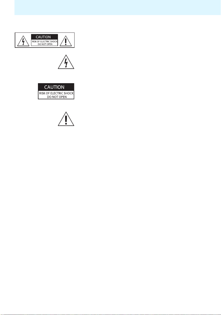
Hazard warnings on the EZL 2020-20 L charging case
The label shown on the left is attached to the rear of
the charging case. The symbols on this label have the
following meaning:
This symbol is intended to alert the user to the
presence of uninsulated dangerous voltage within
the device’s enclosure that may be of sufficient
magnitude to constitute risk of fire or electric shock.
This symbol is intended to alert the user to the risk of
electric shock if the device is opened. There are no user
serviceable parts inside. Refer servicing to qualified
personnel only.
This symbol indicates the presence of important operating and maintenance instructions in the literature
accompanying this device.
Overloading
Do not overload wall outlets and extension cables as
this may result in fire and electric shock.
Replacement parts
When replacement parts are required, be sure the
service technician uses replacement parts specified by
Sennheiser or those having the same characteristics
as the original part. Unauthorized substitutions may
result in fire, electric shock, or other hazards.
Safety check
Upon completion of any service or repairs to this
device, ask the service technician to perform safety
checks to determine that the devices are in a safe
operating condition.
3
Page 5

Important safety instructions
Danger of hearing damage due to high volumes
This is a professional transmission system. Commercial
use is subject to the rules and regulations of the trade
association responsible. Sennheiser, as the manufacturer, is therefore obliged to expressly point out
possible health risks arising from use.
The HDE 2020 D and EK 2020 D receivers are capable
of producing sound pressure exceeding 85 dB(A).
85 dB(A) is the sound pressure corresponding to the
maximum permissible volume which is by law (in
some countries) allowed to affect your hearing for
the duration of a working day. It is used as a basis
according to the specifications of industrial medicine.
Higher volumes or longer durations can damage your
hearing. At higher volumes, the duration must be
shortened in order to prevent hearing damage. The
following are sure signs that you have been subjected
to excessive noise for too long a time:
• You can hear ringing or whistling sounds in your
ears.
• You have the impression (even for a short time
only) that you can no longer hear high notes.
Intended use of the devices
Intended use includes:
• using the devices for professional purposes,
• having read this instruction manual, especially the
chapter “Important safety instructions” on page 2,
• using the devices within the operating conditions
and limitations described in this instruction
manual.
“Improper use” means using the devices other than as
described in this instruction manual, or under operating conditions which differ from those described
herein.
Safety instructions for Li-Polymer and Ni-
MH rechargeable batteries and batteries
4
Page 6
Important safety instructions
If abused or misused, rechargeable batteries may leak. In extreme cases, they may
even present:
CAUTION!
• a heat hazard,
• a fire hazard,
• an explosion hazard,
• a smoke or gas hazard.
Sennheiser does not accept any liability for damage arising from abuse or misuse.
Keep away from children. Observe correct polarity.
Do not heat above 70°C/
158°F, e.g. do not expose to
sunlight or throw into a fire.
Do not expose to moisture.
Do not short-circuit.
Do not mutilate or
dismantle.
Do not pack charged
batteries loose – danger of
shorting out / fire hazard.
Do not continue to use
defective rechargeable
batteries.
Only use original Sennheiser
rechargeable batteries.
Switch rechargeable batterypowered devices off after use.
Only charge rechargeable batteries
with the appropriate Sennheiser
chargers.
When not using rechargeable
batteries for extended periods
of time, charge them regularly
(about every three months).
Only charge rechargeable batteries
at ambient temperatures between
10°C/50°F and 40°C/104°F.
Immediately remove rechargeable
batteries from obviously defective
devices.
Dispose of rechargeable batteries
and devices with built-in rechargeable batteries at special collection
points or return them to your
specialist dealer.
5
Page 7

Important safety instructions
Additional safety instructions for the BA 2015 accupack and for batteries
Immediately remove flat batteries/
Do not solder.
rechargeable batteries from the
device.
Rechargeable batteries must only be replaced by authorized Sennheiser partners.
If abused or misused, rechargeable batteries may be damaged!
6
Page 8

System components
System components
The Tourguide System 2020 D consists of the
following components which are available from your
Sennheiser partner:
• EZL 2020-20 L charging case including
instruction manual of the overall system
• SK 2020 D bodypack transmitter
• SKM 2020 D radio microphone
• HDE 2020 D stethoset receiver
• EK 2020 D receiver
• BA 2015 accupack
•Mains cable
• Microphone (see next section)
7
Page 9

Overview of the system
Overview of the system
The Tourguide System 2020 D offers optimum digital
speech transmission for conferences and guided tours
e.g. in factories or museums. The use of RF transmission allows freedom of movement for all members of
the group. Six preset intermodulation-free receiving
frequencies offer high flexibility and adaptability.
The Tourguide System 2020 D operates in the
863 MHz – 865 MHz frequency band, which is licensefree in Europe. For an overview, refer to page 56.
SK 2020 D bodypack transmitter
You can connect one of the following Sennheiser
microphones (to be ordered separately) to the bodypack transmitter:
• Clip-on microphones:
ME 2-N, ME 4-N, MKE 2-EW GOLD
•Headmics:
ME 3-N, HSP 2-EW, HSP 4-EW, HS 2-EW
• Hand-held microphones with
special connecting cable:
e 815, e 825 S, e 835, e 840, e 845
In addition, you can connect any audio source (e.g. a
flash / MP3 player) to the bodypack transmitter.
SKM 2020 D radio microphone
This extremely rugged radio microphone can be used
in various tour situations. The radio microphone is
easy to configure and use.
For storage and safe transportation, the radio microphone can be placed in the charging case and secured
with Velcro tape.
8
Page 10

Overview of the system
HDE 2020 D and EK 2020 D receivers
The receivers are easy to use and comfortable to wear.
The built-in LC display shows all the important information at a glance (receiving channel, reception
quality, charge status of the built-in Lithium-polymer
rechargeable battery as well as the currently set
volume). The rocker button allows fast and easy
setting of the desired channel.
The EK 2020 D allows you to connect any headphones
or an induction loop for wearers of hearing aids.
The system can be expanded at any time by adding
additional receivers.
EZL 2020-20 L charging case
The charging case simultaneously recharges up to
20 stethoset receivers with their built-in rechargeable
batteries, as well as the BA 2015 accupack of the
bodypack transmitter/radio microphone. You can also
charge the bodypack transmitter with the BA 2015
accupack inserted plus an additional spare accupack.
The channel copy function lets you set all receivers to
the same channel at the press of a button.
Additional features of the charging case:
• Quick charge of accupacks.
• Automatic detection of full charge and subsequent
switching to trickle charging so the accupacks can
remain in the charger even when they have been
fully charged.
• Highest possible operational reliability, since
temperature and voltage of the accupacks are
monitored during charging.
• Long accupack service life due to overcharge
protection and recovery of deep-discharged accupacks.
• Safe storage and transportation of the system
components.
9
Page 11
The operating controls
The operating controls
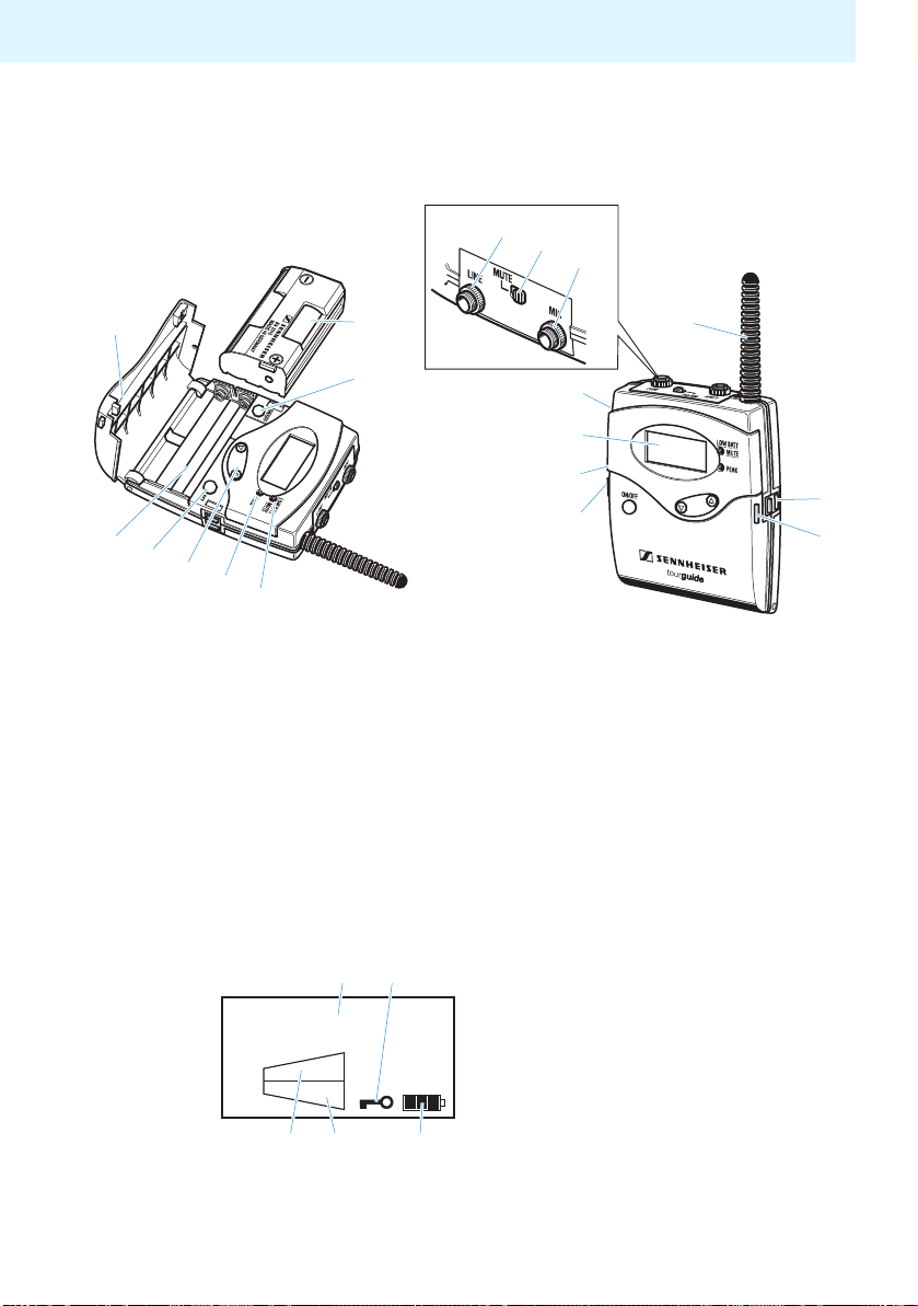
SK 2020 D bodypack transmitter
Line input
MUTE switch
Microphone input
Battery compartment cover
BA 2015 accupack
ON/OFF button
(under battery compartment cover)
Red LED LOW BATT/MUTE
Yellow LED PEAK
/ rocker button
CH 03
LINE
MIC
SET button
(under battery compartment cover)
Battery compartment
Antenna
Charging contacts
Battery compartment catches
LC display
Belt clip
(on the back of the transmitter)
Channel display
Lock mode icon
4-step battery status indication
MIC level display
LINE level display
10
Page 12
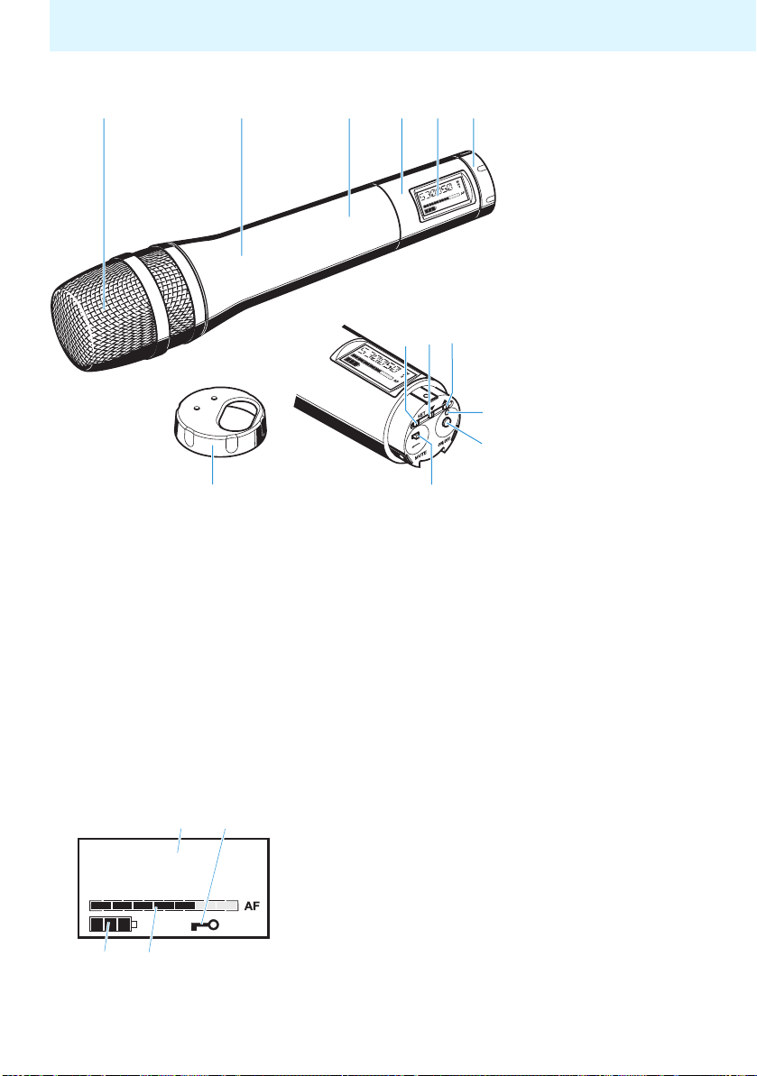
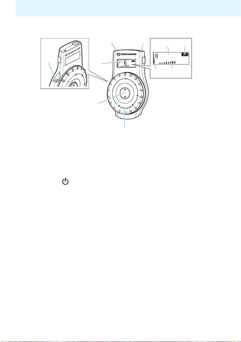
SKM 2020 D radio microphone
The operating controls
Sound inlet basket
Body of radio microphone
Battery compartment
(not visible from outside)
Display section
LC display
CH 03
Turnable protective cap for operating controls
(shown removed);
the following operating controls become accessible in turn by turning the protective cap:
SET button
button
button
Operation / battery status indicator,
red LED (ON/LOW BATT)
ON/OFF button
with ESC function (cancel) in
the operating menu
MUTE switch
Channel display
Lock mode icon
4-step battery status indication
7-step audio level display “AF”
11
Page 13
The operating controls
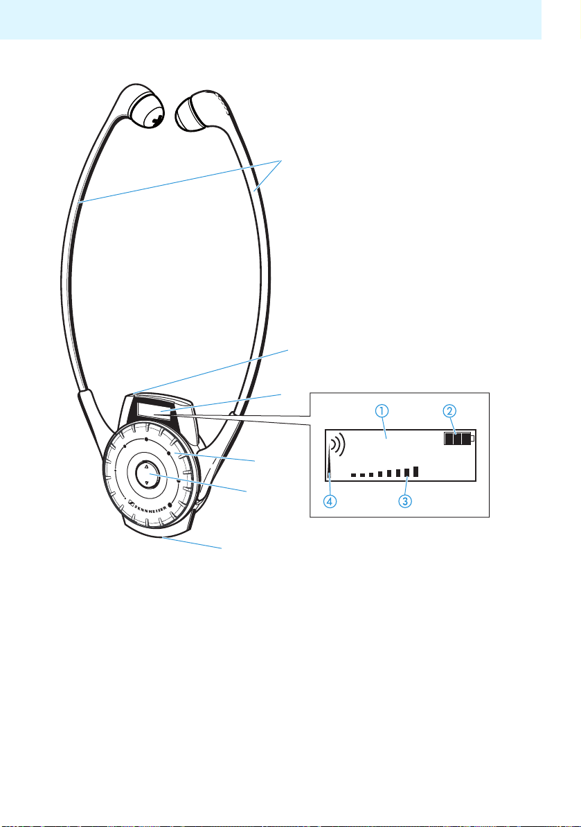
HDE 2020 D stethoset receiver
Earbows
Red/green LED for charge status
LC display
Volume control
Channel selection button /
Charging contacts
12
6
Channel display
4-step battery status display
Volume display
RF signal indication
Page 14
EK 2020 D receiver
The operating controls
Volume control
Channel selection button /
LC display
LED for charge status
ON/OFF button
Headphone socket
6
Channel display
4-step battery status display
Volume display
RF signal indication
13
Page 15
The operating controls
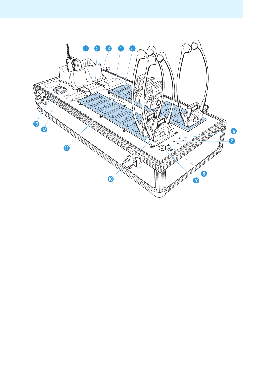
EZL 2020-20 L charging case
Charging compartments for
accupack/bodypack transmitter
Red LED CHARGE/ERROR
Green LED READY
Storage place for radio microphone
19 charging compartments for
receivers (slaves, light blue in
the diagram)
LED POWER
LED TEMP ERROR
14
LED COPY AVAILABLE
COPY button
Charging compartment with
channel copy function (master)
Air vents
IEC mains socket
Mains switch
Page 16
LINE
MIC
CH 03
The operating controls
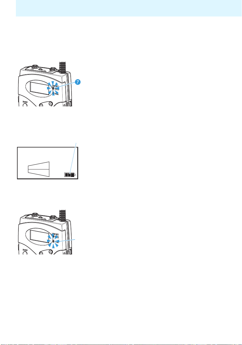
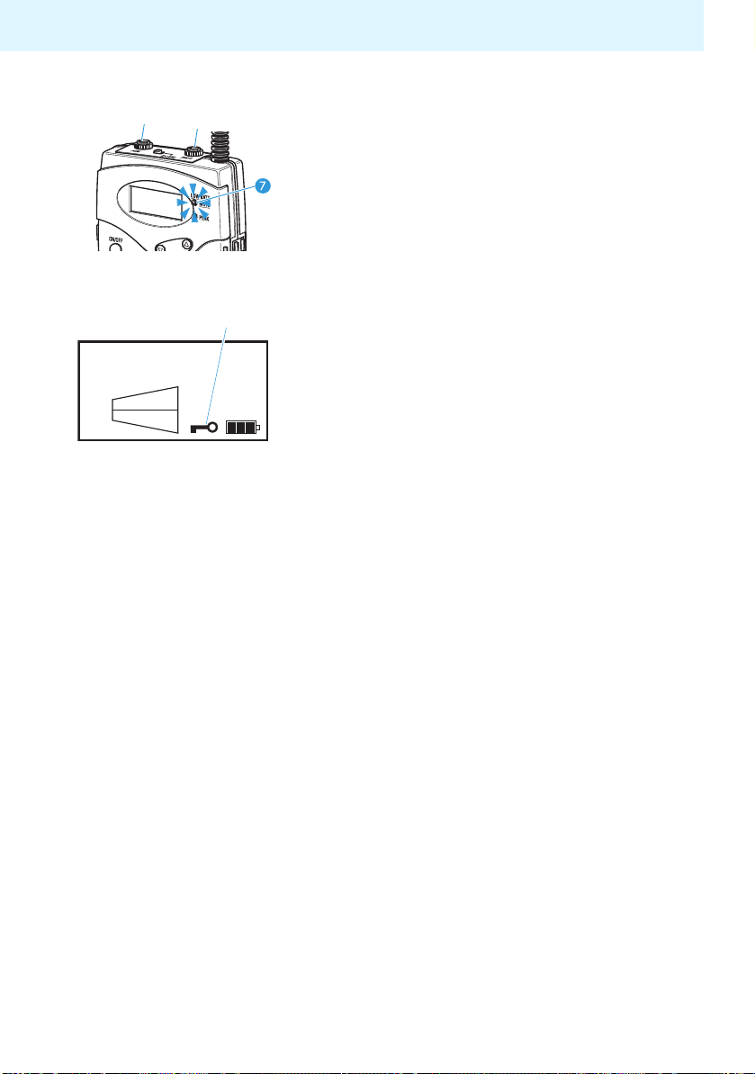
Indications and displays on the bodypack transmitter
Operation and battery status indication
The red LED LOW BATT/MUTE provides information
on the current operating state of the bodypack transmitter:
Red LED off:
The bodypack transmitter is switched on and the capacity of the batteries/BA 2015 accupack is sufficient.
Red LED flashing:
The batteries are/the BA 2015 accupack is going flat
(LOW BATT).
In addition, the 4-step battery status display on the
display panel provides information on the remaining
battery/BA 2015 accupack capacity:
3 segments capacity approx. 100%
2 segments capacity approx. 70%
1 segments capacity approx. 30%
Battery icon flashing LOW BATT
AF peak indication
The yellow LED PEAK lights up when the transmitter’s audio input is overmodulated.
If the transmitter’s audio input level is excessively
high, the sound of the receivers may be distorted.
In order to avoid distortion in the receivers, reduce
the sensitivity of the transmitter’s line and/or microphone input (see “Changing the sensitivity of the
bodypack transmitter’s line input” on page 41 and
“Changing the sensitivity of the bodypack transmitter’s microphone input” on page 42).
15
Page 17
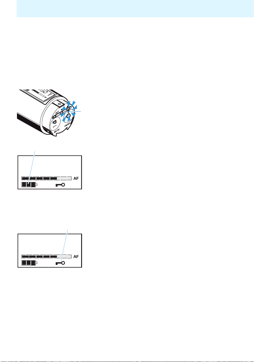
The operating controls
MUTE display
LINE
MIC
CH 03
The red LED LOW BATT/MUTE lights up when the
transmitter's microphone input is muted (see “Muting
the devices” on page 39).
Note:
The muting function (MUTE) mutes the microphone
input only, not the line input .
Lock mode icon
The lock mode icon appears on the display when
the lock mode is activated (see “Activating/deactivating the lock mode” on page 45).
Display backlighting
After pressing a button, the display remains backlit
for approx. 30 seconds.
Display of the energy saving mode
When there is no audio signal for 5 minutes or when
the bodypack transmitter is muted, it automatically
switches to energy saving mode. “CH OFF” appears on
the display and the transmission signal is deactivated.
When an audio signal reaches the bodypack transmitter, it automatically switches back to normal operation and the display displays the selected channel.
16
Page 18
The operating controls
Indications and displays on the radio microphone
Operation and battery status indication
The red LED (LOW BATT/ON) provides information
on the current operating state of the radio microphone:
Red LED off:
The radio microphone is switched on and the capacity
of the batteries/BA 2015 accupack is sufficient.
Red LED flashing:
The batteries are/the BA 2015 accupack is going flat
(LOW BATT)!
CH 03
CH 03
In addition, the 4-step battery status display on the
display panel provides information on the remaining
battery/BA 2015 accupack capacity:
3 segments capacity approx. 100%
2 segments capacity approx. 70%
1 segments capacity approx. 30%
Battery icon flashing LOW BATT
Lock mode icon
The lock mode icon appears on the display when
the lock mode is activated (see “Activating/deactivating the lock mode” on page 45).
17
Page 19
The operating controls
CH 03
CH 03
Modulation display
The level display for audio signal “AF” shows the
modulation of the radio microphone.
When the radio microphone’s audio input level is
excessively high, the level display for audio signal
“AF” shows full deflection for the duration of
the overmodulation. You can change modulation by
changing the input sensitivity of the radio microphone as described on page 43.
MUTE display
When the radio microphone is muted, “MUTE”
appears on the display (see “Muting the radio microphone” on page 39).
Display backlighting
After pressing a button, the display remains backlit
for approx. 15 seconds.
Display of the energy saving mode
When there is no audio signal for 5 minutes or when
the radio microphone is muted, it automatically
switches to energy saving mode. “CH OFF” appears on
the display and the transmission signal is deactivated.
When an audio signal reaches the radio microphone,
it automatically switches back to normal operation
and the display displays the selected channel.
18
Page 20
6
The operating controls
Indications and displays on the receiver
RF signal indication
The RF signal indication (tower with radio waves)
on the LC display provides information on the
RF signal reception:
Tower with radio waves:
An RF signal is being received on the selected channel.
Tower without radio waves:
No RF signal is being received on the selected channel
or the received signal level is too low.
No tower, no radio waves
HDE 2020 D only: The receiver is in standby mode. You
can, however, change the settings on the receiver.
Signal strength
The received signal strength may be reduced due to
body absorption of the RF signal.
Charge status LED
During charging,
•the LED of the EK 2020 D or
•the LED of the HDE 2020 D
provides information on the charge status of the
receiver’s built-in rechargeable battery.
19
Page 21

The operating controls
6
6
LED lights up red:
The built-in rechargeable battery is being charged.
LED lights up green:
The built-in rechargeable battery is fully charged. The
receiver is now ready for operation.
LED slowly flashes red:
The temperature of the built-in rechargeable battery
is outside the permissible range (3°C to 40°C). The
charging process is interrupted until the temperature
is again within the admissible
LED lights up yellow/orange:
The built-in rechargeable battery is defective. Please
contact your Sennheiser partner.
Volume display
The volume display provides information on the
current volume level.
Channel display
The channel display provides information on the
currently selected channel.
range.
20
6
Battery status display
The 4-step battery status display provides information on the capacity of the receiver’s built-in
rechargeable battery.
Shortly before the rechargeable battery is completely
discharged, the display backlighting flashes, indicating that the receiver will soon switch off automatically.
Page 22

The operating controls
Indications and displays on the charging case
Operation indication
The LED POWER lights up as long as the mains
supply is switched on.
Temperature indication
The LED TEMP ERROR lights up if the temperature in
the charging case gets too high and will remain on
until the temperature drops to a safe level. All charging processes are interrupted until the temperature
drops to a safe level.
LED indication for “automatic copying” function
The LED COPY AVAILABLE lights up green when
the “automatic copying” function is available. This
happens
• when a switched-on receiver is placed into the
charging compartment with channel copy
function (master)
• and at least one receiver is placed into one of the
other receiver charging compartments (slaves,
light blue in the diagram) .
The LED COPY AVAILABLE goes off when the “automatic copying” function is not available. This happens
• when the receiver in the charging compartment
with channel copy function (master) is switched
off,
• or when the receiver is removed from the charging
compartment with channel copy function
(master) ,
• or when all 19 charging compartments (slaves)
are empty.
21
Page 23

The operating controls
LED indication for charging compartments for
BA 2015 accupack/bodypack transmitter
Each charging compartment for accupack/bodypack
transmitter has an LED CHARGE/ERROR and an
LED READY which indicate the following operating
states:
No LED lit:
• The charging compartment for accupack/bodypack
transmitter is ready for operation but empty.
OR:
• A bodypack transmitter without accupack has been
placed into the charging compartment.
Red LED CHARGE/ERROR lit:
The accupack is being charged. A red flashing LED for
error indication, as with the L 2015 charger, is not
available on the EZL 2020-20 L charging case.
Green LED READY lit:
The accupack is fully charged and the charging case
has switched to trickle charging.
22
Green LED READY lights up briefly and then goes
off:
The bodypack transmitter is powered by standard
batteries which cannot be recharged.
Page 24

The operating controls
ON/OFF
SET
The functions of the operating controls of the bodypack transmitter/radio microphone
LOW BATT
MUTE
PEAK
ON/OFF
SET
Bodypack transmitter
Operating control Mode* Function
Switched off Pressing the button: Switches the bodypack
transmitter/radio microphone on
Switched on Pressing the button for approx. 3 seconds:
Switches the bodypack transmitter/radio
ON/OFF button
SET button
/ buttons
Selection mode Cancels the selection and returns to the
Setting mode Cancels the entry and returns to the selection
Standard display Changes to the selection mode
Selection mode Changes to the setting mode of the selected
Setting mode Stores the setting and returns to the selection
Lock mode
activated
Standard display No function
Selection mode Changes to the previous menu item () or
Setting mode Increases (
microphone off
standard display (ESC function)
mode without storing the changes made
(ESC function)
menu
mode (“STORED” is displayed briefly)
Changes directly to the “LOCK” menu item
where you can deactivate the lock mode
changes to the next menu item (
of the selected menu item or switches the
menu item (ON) or (OFF)
Radio microphone
)
) or reduces () the setting
* For information on the menu areas “standard display“, “selection mode” and “setting
mode“, please see “Overview of the bodypack transmitter’s operating menu” on page 49.
23
Page 25

The operating controls
The functions of the operating controls of the receivers
HDE 2020 D Operating control Function
Volume control Turning the volume control:
Channel selection button
/
Earbows Pulling the earbows apart:
EK 2020 D Operating control Function
Volume control Turning the volume control:
Channel selection
button /
ON/OFF button
Switches the receiver on/off
Changes the volume
Changes to the next channel ()
or changes to the previous
channel ()
Switches the stethoset receiver on
Changes the volume
Changes to the next channel ()
or changes to the previous
channel ()
The functions of the operating controls of the charging case
Operating control Function
COPY button Starts the channel copy function (see page 37)
Mains switch Switches the charging case on/off
24
Page 26

Putting the components into operation
Putting the components into
operation
Setting up the charging case
Note:
The charging case as well as the accupacks and the
receivers’ built-in rechargeable batteries will get
hot during charging. Please ensure the following so
that the generated heat can dissipate:
• The air vents of the charging case must not be
covered or blocked.
• The charging case must be kept away from heat
sources and must never be exposed to direct
sunlight.
• During charging, do not put the case cover on the
charging case.
The charging case has four plastic feet to ensure that
it cannot slip on the surface on which it is placed.
CAUTION!
Place the charging case on a flat, even surface.
Connect the supplied mains cable to the IEC mains
socket on the charging case.
Connect the mains cable to a wall socket.
Note:
The case cover can be used as a stand for the
charging case (see diagram on the left).
Some furniture surfaces have been
treated with varnish, polish or synthetics
which might cause stains when they
come into contact with other synthetics.
Despite a thorough testing of the synthetics used by us, we cannot rule out the
possibility of staining.
25
Page 27

Putting the components into operation
Inserting and replacing the batteries/accupack of
the radio microphone
For powering the radio microphone, you can either use
the rechargeable BA 2015 accupack or two 1.5 V
AA size batteries. NB: Do not use any other rechargeable batteries!
Unscrew the display section from the radio micro-
phone’s body by turning it counterclockwise.
Slide back the the display section as far as it will
go.
26
Open the battery compartment cover .
Insert the batteries or the BA 2015 accupack as
shown on the battery compartment cover. Observe
correct polarity when inserting the batteries/accupack.
Close the battery compartment cover .
Push the battery compartment into the radio
microphone’s body.
Screw the display section tight.
Page 28

Putting the components into operation
Note:
Always charge the accupack in the charging
compartment of the charging case (see “Charging the BA 2015 accupack” on page 33).
Inserting and replacing the batteries/accupack of
the bodypack transmitter
For powering the bodypack transmitter, you can
either use the rechargeable BA 2015 accupack or
two 1.5 V AA size batteries. NB: Do not use any other
rechargeable batteries!
Push the two battery compartment catches and
open the battery compartment cover .
Insert the BA 2015 accupack or the batteries as
shown in the diagram on the left. Please observe
correct polarity when inserting the accupack/
batteries.
Close the battery compartment cover .
Connecting a microphone to the bodypack
transmitter
Note:
Suitable Sennheiser microphones are listed on
page 8.
Connect the microphone to the microphone
input of the bodypack transmitter.
Lock the plug by screwing down the coupling ring.
Adjust the sensitivity of the microphone input as
described on page 42.
27
Page 29

Putting the components into operation
Connecting external audio sources
You can connect an external audio source such as a CD
player, MP3 player, tape player, etc. to the bodypack
transmitter. (Please note that you cannot connect a
second microphone.) Both signals – the microphone
input signal and the line input signal – are mixed
together equally in the transmitter.
Connect the line output of the external audio
source to the line input of the bodypack transmitter.
Lock the plug by screwing down the coupling ring.
Switch the line input on as described on page 40.
Adjust the sensitivity of the line input as described
on page 41.
Mic input (dynamic):
Signal
LINE input:
Signal
Mic input (Electret):
Signal
LINE input:
Signal
LINE input:
Signal
Attaching the bodypack transmitter to clothing
The bodypack transmitter is attached to clothing (e.g.
belt, waistband) with the supplied belt clip .
The clip is detachable so that you can also attach the
bodypack transmitter with the antenna pointing
downwards. To do so, withdraw the clip from its
fixing points and attach it the other way round.
28
Page 30

Using the components
Using the components
Switching the devices on/off
Notes:
• Remove the batteries or the accupack when the
bodypack transmitter/radio microphone will not
be used for extended periods of time.
• If no transmission is to take place, switch the
transmitters off in order to free up the frequency
range for other applications.
Switching the bodypack transmitter on/off
To switch the bodypack transmitter on:
Briefly press the ON/OFF button .
The display indicates the device name and then
switches to the standard display.
To switch the bodypack transmitter off:
Press and hold the ON/OFF button until “OFF”
appears on the display.
Switching the radio microphone on/off
To switch the radio microphone on:
Turn the protective cap so that the ON/OFF
button becomes accessible.
Press the ON/OFF button to switch the radio
microphone on.
The red LED lights up. The display indicates
the device name and then switches to the standard
display.
To switch the radio microphone off:
Press and hold the ON/OFF button until “OFF”
appears on the display.
The display and the red LED go off.
29
Page 31

Using the components
Automatically switching the HDE 2020 D on/off
The receiver automatically switches on when you pull
the earbows apart. The display switches on.
When you release the earbows, the receiver switches
to standby mode (audio deactivated) and then
switches off after 2minutes.
Switching the EK 2020 D on/off
You can connect an induction loop or any pair of headphones with a 3.5 mm mono or stereo jack plug to the
headphone socket of the EK 2020 D. The headphone impedance must be 32 : or higher.
Connect the 3.5 mm jack plug of your headphones
to the headphone socket of the EK 2020 D.
To switch the receiver on:
Briefly press the ON/OFF button .
The display switches on.
To switch the receiver off:
Press the ON/OFF button for 3 seconds.
When you unplug the headphones from the receiver
or switch off the transmitter, the receiver automatically switches off after 5 minutes.
30
Switching the charging case on/off
To switch the charging case on:
Set the mains switch to the position “I”.
The LED POWER
To switch the charging case off:
Set the mains switch to the position “0”.
The LED POWER goes off.
lights up.
Page 32

Using the components
Note:
When not using the charging case for extended
periods of time, switch it off and disconnect it from
the mains by pulling out the mains connector from
the wall socket.
Adjusting the volume
Adjusting the volume on the receiver
6
CAUTION!
Use
• the volume control of the HDE 2020 D or
• the volume control of the EK 2020 D
to adjust the volume so that you can hear the
speaker’s voice loud and clear.
Note:
The volume control or has no end stop, i. e.
you can turn it endlessly to the left or right.
Danger of hearing damage!
Listening at high volume levels for long
periods can lead to permanent hearing
defects.
Adjust the volume to a low level
before using the receiver.
31
Page 33

Using the components
Charging the rechargeable batteries
CAUTION!
Charging the accupack in the bodypack transmitter
To charge the bodypack transmitter in the EZL 202020 L charging case:
Place the transmitter with the accupack inserted
into the charging compartment for accupack/bodypack transmitter as shown in the diagram on the
left
When placed into a charging compartment, the
bodypack transmitter automatically switches off.
The red LED CHARGE/ERROR of the charging
compartment lights up.
After the accupack has been fully charged, the green
LED READY lights up.
Notes:
• Charging a completely discharged accupack takes
approx. 3½ hours at room temperature.
• Alternatively, you can remove the accupack from
the bodypack transmitter and insert it into the
charging compartment for accupack/bodypack
transmitter as described in the following
section.
• The charging case has no error indication like the
one on the L 2015 charger (“red flashing LED”).
• Only use the charging case for charging the SK 2020 D bodypack transmitter, the HDE 2020 D and EK 2020 D
receivers and the BA 2015 accupack.
• Never try to charge other rechargeable
batteries or non-rechargeable batteries!
.
32
Page 34

Using the components
Charging the BA 2015 accupack
To charge the accupack of the radio microphone or
bodypack transmitter:
Remove the accupack as described on page 26 or
page 27.
Place the accupack into the charging compartment
for accupack/bodypack transmitter as shown in
the diagram on the left.
The red LED CHARGE/ERROR of the charging
compartment lights up.
After the accupack has been fully charged, the green
LED READY lights up.
Notes:
• Charging a completely discharged accupack takes
approx. 3½ hours at room temperature. It is
normal for the accupacks to get hot during
charging.
• However, the charging process may take longer
if:
• the accupack is deep-discharged and first
has to be reconditioned by a deep discharge
recovery charge,
• the ambient temperature is close to or over
40°C, since, in order to protect the accupack,
the charging process will be interrupted until
the temperature has dropped to a safe level.
• For safety reasons, each charging process will be
interrupted after 4 hours.
• When not using the BA 2015 accupack for
extended periods of time, charge it about every
three to six months.
33
Page 35

Using the components
Charging the receivers’ built-in rechargeable batteries
Place the receiver into one of the charging com-
partments for receivers / (light blue in the
diagram).
•The LED of the HDE 2020 D or
•the LED of the EK 2020 D
lights up (see table).
LED colour Meaning
red The built-in rechargeable battery is
being charged.
green The built-in rechargeable battery is
fully charged.
red
(flashing)
yellow/
orange
The temperature of the built-in rechargeable
battery is over 40°C or below 3°C.
The built-in rechargeable battery is defective.
Interrupt the charging process and contact
your Sennheiser Service.
Notes:
• Charging a completely discharged rechargeable
battery of the HDE 2020 D takes approx. 2½ hours
at room temperature.
• Charging a completely discharged rechargeable
battery of the EK 2020 D takes approx. 5 hours at
room temperature.
• However, the charging process may take longer if:
• the rechargeable battery is deep discharged
and first has to be reconditioned by a deep
discharge recovery charge,
•
the temperature of the built-in rechargeable
battery is over 40°C or below 3°C, since, in order
to protect the rechargeable battery, the charging process will be interrupted until the temperature is again within the permissible range
(the LED of the HDE 2020 D or the LED of
the EK 2020 D flashes red).
34
Page 36

Using the components
• An additional temperature protection prevents
overheating inside the charging case. If the temperature inside the charging case exceeds safety
limits, the charging process will be interrupted
and will only be restarted when the charging case
has cooled down.
• When not using the receivers for extended
periods of time, charge them about every six
months in order to prevent deep discharge
damage to the rechargeable batteries.
Setting a channel
To set the complete system to a certain channel,
proceed as follows:
1. Set the bodypack transmitter/radio microphone to
the desired channel (see next section).
2. Set one of the receivers to the same channel (see
“Setting the channel on the receiver” on page 37).
3. Automatically set all other receivers to the same
channel using the channel copy function (see
“Setting the receiver channel(s) using the channel copy function” on page 37).
Setting the channel on the bodypack transmitter/
radio microphone
To set the bodypack transmitter or the radio microphone to the desired channel, use the operating menu
of the device. An overview of the operating menus is
given from page 49 onwards.
35
Page 37

Using the components
ON/OFF
SET
Make sure that the lock mode is deactivated
(see “Activating/deactivating the lock mode” on
page 45).
LOW BATT
MUTE
PEAK
ON/OFF
SET
Bodypack transmitter
Radio microphone
Press the SET button.
The operating menu appears and the first menu
item “CHAN” flashes on the display.
Press the SET button.
The current channel flashes on the display.
Press / to change the channel.
If you press , the display jumps to the next
channel; if you press , the display jumps to the
previous channel.
By pressing and holding the / buttons, the
display cycles continuously (repeat function).
Press the SET button to permanently store the
selected channel.
“STORED” briefly appears on the display. The bodypack transmitter or the radio microphone now
transmits on the selected channel. The last menu
item selected is shown on the display.
To exit the operating menu:
Use / to select the “EXIT” menu item and press
the SET button.
The standard display is shown.
36
Or:
Press and hold the ON/OFF button until the stand-
ard display is shown.
Page 38

6
Using the components
Setting the channel on the receiver
In order for the receiver to receive the signal from
the bodypack transmitter or radio microphone, it has
to be set to the same channel.
To manually set the receiver channel:
Press
• the channel selection button / of the
HDE 2020 D or
• the channel selection button / of the
EK 2020 D.
The channel changes. The selected channel is
shown on the channel display .
If the bodypack transmitter or radio microphone
is transmitting on this channel, the RF signal
indication indicates the field strength of the
received RF signal.
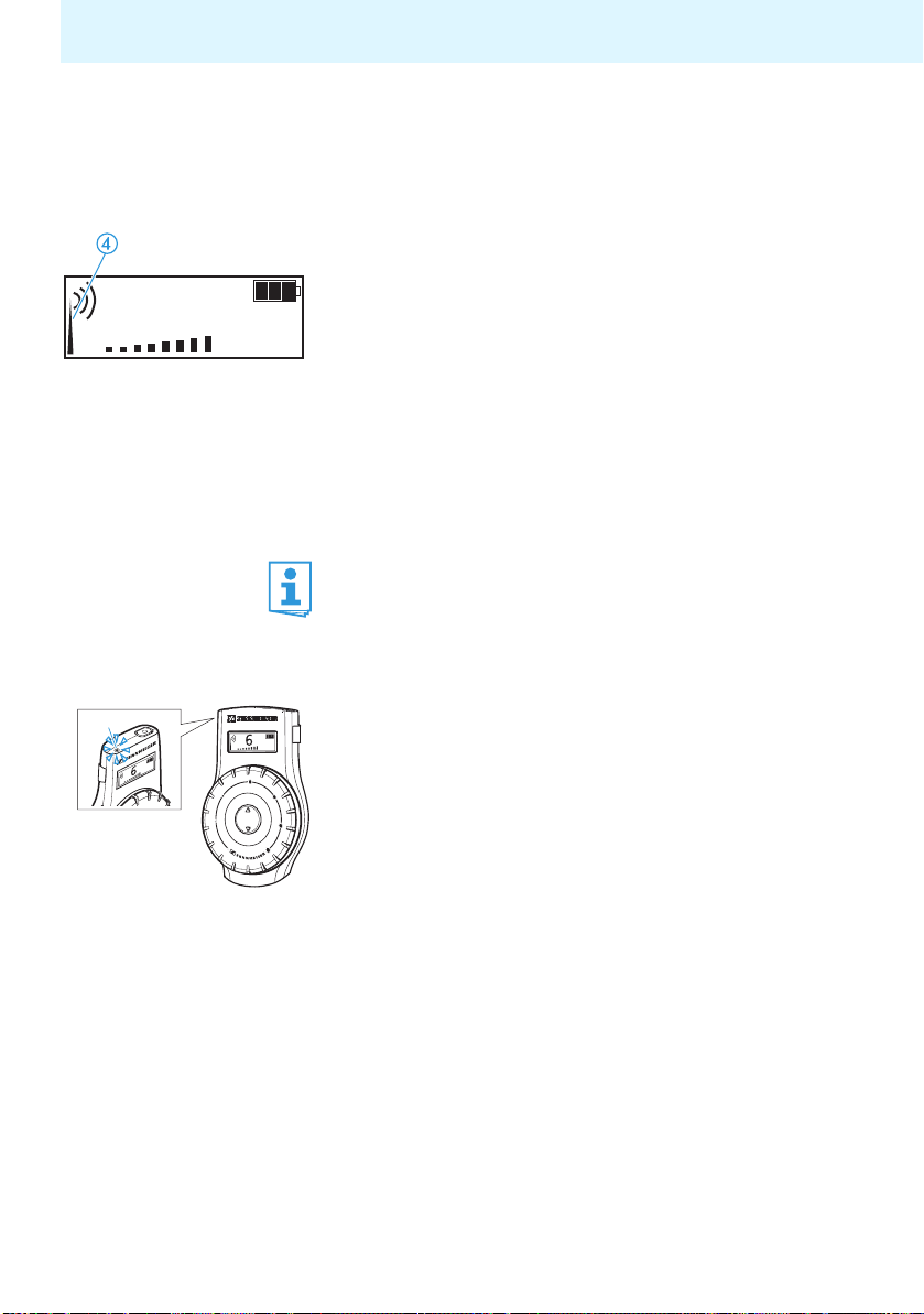
Setting the receiver channel(s) using the channel
copy function
The channel copy function lets you simultaneously set
a maximum of 19 receivers in the charging case to the
same channel. This is achieved by copying the current
channel of the receiver placed into the charging compartment with channel copy function (master) to
all other receivers in the charging case.
Place all receivers which are to be set to the same
channel into the charging compartments for
receivers (slaves, light blue in the diagram) .
Switch on the receiver whose channel you want to
copy.
Place this receiver into the charging compartment
with channel copy function (master) .
The LED COPY AVAILABLE lights up green as long
as the channel copy function is available.
Press the COPY button to start the channel copy
function.
The displays of all receivers which are successfully
set to the same channel light up.
37
Page 39

Using the components
Notes:
• If the receivers’ built-in rechargeable batteries
are not discharged, you can use the channel copy
function even when the charging case is not
connected to the mains.
• If you do not press the COPY button , the
receiver placed into the charging compartment
with channel copy function (master) will automatically switch off after approx. 2 minutes.
Using several Tourguide systems simultaneously
If you are using the Tourguide System 2020 D to run
several guided tours simultaneously, the systems
could interfere with one another. To prevent this
happening, you have to set the systems to different
channels (a system consits of one bodypack transmitter or one radio microphone and any number of
receivers).
38
Page 40

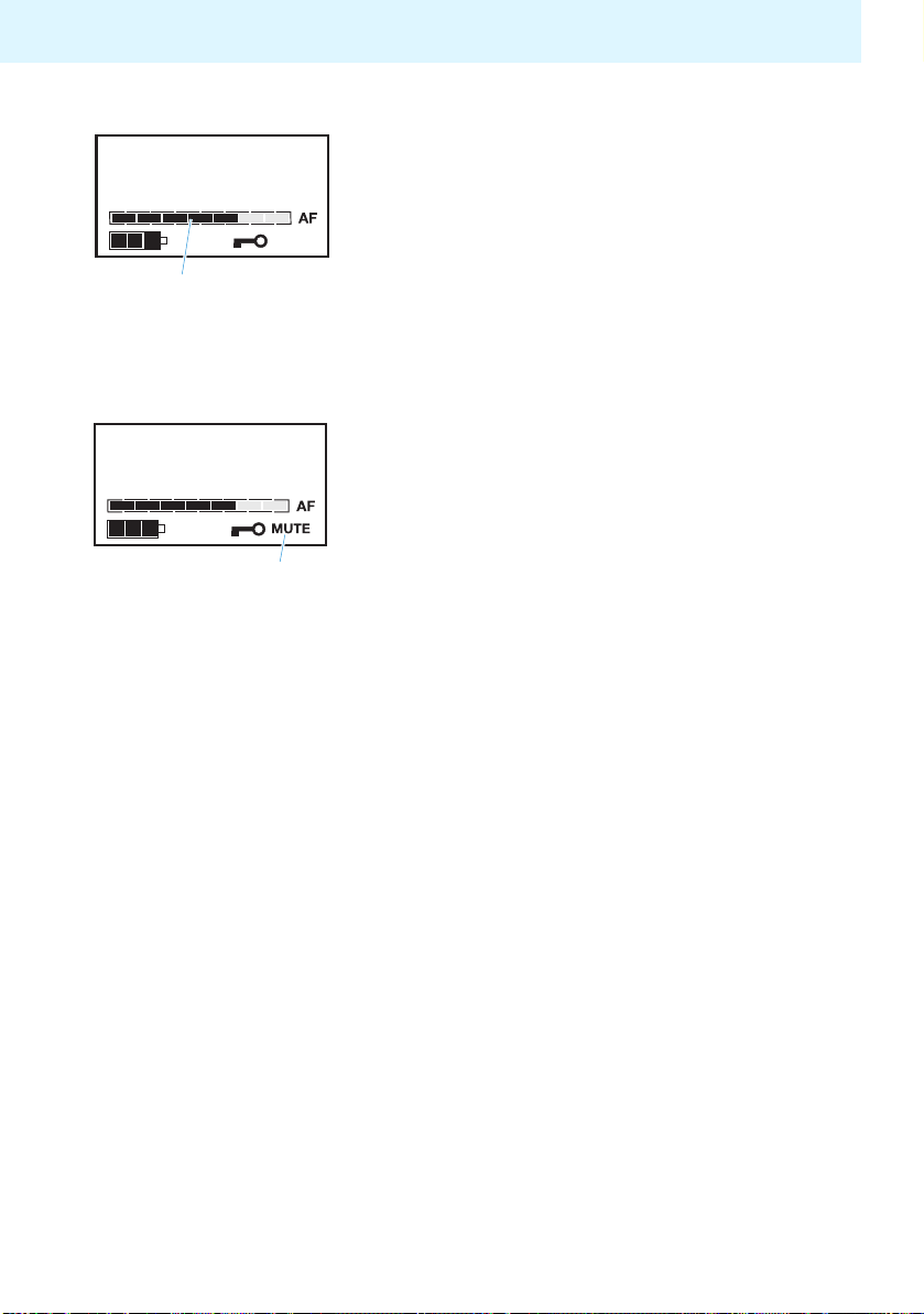
Muting the devices
Muting the bodypack transmitter
Using the components
CH 03
LINE
MIC
Slide the MUTE switch to the left, to “MUTE“.
The red LED LOW BATT/MUTE lights up perma-
nently. The MIC level display no longer shows
any deflection. The bodypack transmitter’s microphone input is muted.
Note:
The muting function (MUTE) mutes the microphone
input but not the line input . This function
enables a pre-recorded track to be played through
the line input without being disturbed by the tour
guide’s microphone. When the track has finished,
the guide can un-mute the microphone and continue talking.
To deactivate the muting function:
Slide the MUTE switch back to the right.
The red LED LOW BATT/MUTE goes off. The MIC
level display and the LINE level display indicate the current levels.
Muting the radio microphone
Turn the protective cap so that the MUTE
switch becomes accessible.
Slide the MUTE switch in the direction of the
arrow.
“MUTE” appears on the display of the radio microphone. After 5 minutes, “CH OFF” appears on the
display (see “Display of the energy saving mode”
on page 16).
To deactivate the muting function:
Slide the MUTE switch back in order to transmit
the audio signal again.
39
Page 41

Using the components
Special bodypack transmitter/radio microphone settings
The following special settings can only be made via
the bodypack transmitter’s/radio microphone’s operating menu. An overview of this operating menu is
given from page 49 onwards.
Switching the bodypack transmitter’s line
input on/off
You can connect an audio source such as a CD player,
MP3 player, etc. to the bodypack transmitter’s line
input. If you have connected an audio source, you then
have to switch on the line input as follows:
Press the SET button .
The operating menu appears and the first menu
item “CHAN” flashes on the display.
Repeatedly press the / rocker button in the
direction until “LINE” flashes on the display.
Press the SET button .
If the line input is switched off, “LINE.OFF” flashes
on the display; if the line input is switched on,
“LINE.ON” flashes on the display.
Press the / rocker button to change the
setting.
Press the SET button to permanently store the
setting.
“STORED” briefly appears on the display.
Adjust the sensitivity of the line input to match the
connected audio source as described in the following section.
40
Page 42

LINE
MIC
CH 03
Using the components
Changing the sensitivity of the bodypack
transmitter’s line input
To adjust the sensitivity of the line input to match the
connected audio source:
Make sure that the line input is switched on (see
previous section).
Connect the external audio source, switch it on and
start playback.
Press the SET button .
The operating menu appears and the first menu
item “CHAN” flashes on the display.
Repeatedly press the / rocker button until
“SENSIT” flashes on the display and the LINE level
display appears.
Press the SET button .
The current input sensitivity and the LINE level
display appear on the display.
Press the / rocker button to change the
input sensitivity so that the LINE level display
shows full deflection during the loudest passages,
but the yellow LED PEAK does not light up permanently.
Press the SET button to permanently store the
setting.
“STORED” briefly appears on the display, indicating
that the sensitivity of the line input has been
stored.
41
Page 43

Using the components
CH 03
LINE
MIC
Changing the sensitivity of the bodypack
transmitter’s microphone input
To adjust the sensitivity of the microphone input to
match the connected microphone:
Connect the microphone, position it correctly (refer
to the microphone’s instruction manual) and speak
into the microphone as usual.
Press the SET button .
The operating menu appears and the first menu
item “CHAN” flashes on the display.
Repeatedly press the / rocker button until
“SENSIT” flashes on the display and the MIC level
display appears.
Press the SET button .
The current input sensitivity and the MIC level
display appear on the display.
Press the / rocker button to change the
input sensitivity so that the MIC level display
shows full deflection during the loudest passages,
but the yellow LED PEAK does not light up
permanently.
Press the SET button to permanently store the
setting.
“STORED” briefly appears on the display, indicating
that the sensitivity of the microphone input has
been stored.
42
Page 44

-36. dB
Using the components
Adjusting the radio microphone’s input sensitivity
The input sensitivity is adjusted too high when close
talking distances or speakers with loud voices cause
overmodulation in the transmission link. When the
audio input level is excessively high, the audio level
display (AF) shows full deflection.
If, on the other had, the input sensitivity is adjusted
too low, the transmission link will be undermodulated,
which would result in a signal with high background
noise.
The input sensitivity is correctly adjusted when the
audio level display (AF) only shows full deflection only
during the loudest passages.
To adjust the sensitivity of the radio microphone:
Press the SET button .
The operating menu appears and the first menu
item “CHAN” flashes on the display.
Repeatedly press the / buttons / until
“SENSIT” flashes on the display and the audio level
display appears.
Press the SET button .
The current input sensitivity and the audio level
display appear on the display.
Press the / buttons / to change the setting
so that the audio level shows full deflection only
during the loudest passages.
Press the SET button to permanently store the
setting.
“STORED” briefly appears on the display. indicating
that the input sensitivity of the radio microphone
has been stored.
The following figures are a guide to the best settings:
• Presentation: –24 to –12 dB
• Interview: –12 to 0 dB
43
Page 45

Using the components
ON/OFF
SET
Displaying the transmission frequency of the
bodypack transmitter/radio microphone
To display the transmission frequency assigned to the
current channel:
LOW BATT
MUTE
PEAK
ON/OFF
SET
Bodypack transmitter
Radio microphone
Press the SET button.
The operating menu appears and the first menu
item “CHAN” flashes on the display.
Repeatedly press / until “FREQ” flashes on the
display.
Press the SET button.
The transmission frequency assigned to the current
channel appears on the display. You cannot change
this transmission frequency.
Press the ON/OFF button or the SET button to
return to the operating menu.
44
Page 46

Using the components
ON/OFF
SET
Loading the factory-preset default settings
To load the factory-preset default settings of the
bodypack transmitter/radio microphone:
LOW BATT
MUTE
PEAK
ON/OFF
SET
Bodypack transmitter
Radio microphone
Press the SET button.
The operating menu appears and the first menu
item “CHAN” flashes on the display.
Repeatedly press / until “RESET” flashes on the
display.
Press the SET button.
“RST.OK” flashes on the display.
Press the SET button to load the factory-preset
default settings.
“DONE” briefly appears on the display. The bodypack transmitter/radio microphone is reset to the
following factory-preset default settings:
• Channel: 1
• Line input: switched off
(bodypack transmitter only)
• Input sensitivity:
– Line input: –24 dB
(bodypack transmitter only)
– Microphone input: –12 dB
• Lock mode: deactivated
• Infra-red service interface: deactivated
Activating/deactivating the lock mode
The lock mode prevents the bodypack transmitter/
radio microphone from being accidentally programmed or switched off during operation.
45
Page 47

Using the components
ON/OFF
SET
To activate the lock mode:
LOW BATT
MUTE
PEAK
ON/OFF
SET
Bodypack transmitter
Radio microphone
Press the SET button.
The operating menu appears. The first menu item
“CHAN” flashes.
Repeatedly press / until “LOCK” appears on the
display.
Press the SET button.
“LOC.OFF” flashes on the display.
Press /.
“LOC.ON” flashes on the display.
Press the SET button to activate the lock mode.
“STORED” briefly appears on the display, indicating
that the lock mode has been activated. The lock
mode icon is displayed on the standard display.
To deactivate the lock mode:
Press the SET button.
“LOC.ON” flashes on the display.
Press /.
“LOC.OFF” flashes on the display.
Press the SET button to deactivate the lock mode.
“STORED” briefly appears on the display, indicating
that the lock mode has been deactivated. The lock
mode icon is no longer displayed on the standard display.
46
Page 48

Using the components
ON/OFF
SET
Displaying the version number of the bodypack
transmitter/radio microphone
To display the version number of the operating
system installed:
LOW BATT
MUTE
PEAK
ON/OFF
SET
V 1.001
Bodypack transmitter
Radio microphone
Press the SET button.
The operating menu appears and the first menu
item “CHAN” flashes on the display.
Repeatedly press / until “SERVIC” flashes on
the display.
Press the SET button.
The version number is displayed.
47
Page 49

Using the components
The operating menu of the bodypack transmitter/radio microphone
The bodypack transmitter’s/radio microphone’s operating menu contains the following menu items:
Menu item Meaning
CHAN Selects a channel (see page 35)
LINE*
SENSIT (LINE)*
SENSIT (MIC)
FREQ
RESET
LOCK
SERVIC Displays the version number (see page 47)
EXIT Exits the operating menu
Switches the line input on/off
(see page 40)
Changes the sensitivity of the line input
(see page 41)
Changes the sensitivity of the microphone
input (see page 42)
Displays the frequency of the current
channel (see page 44)
Loads the factory-preset default settings
(see page 45)
Activates/deactivates the lock mode
(see page 45)
48
*) only available with bodypack transmitter
Page 50

Using the components
Overview of the bodypack transmitter’s operating menu
Use the ON/OFF button to cancel your entry in all areas of the operating menu.
Setting modeSelection mode
EXIT
3 sec.
CH 01
SET
CHAN CH 01 CH 04
SET
Selecting the
channel
Current channel
STORED
LINE LIN. OFF LIN. ON
Switching the
line input on/off
SET
Current setting
STORED
SENSIT -24. dB -06. dB
Adjusting the
sensitivity of
the line input
SET
Current
sensitivity
setting
STORED
SENSIT -36. dB -06. dB
Adjusting the
sensitivity of the
microphone input
SET
Current
sensitivity
setting
STORED
FREQ 863.124
SET
/ :
01...06
Stores settings
SET
/ :
OFF, ON
Stores settings
SET
/ :
0...-24
Stores settings
SET
/ :
0...-36
Stores settings
SET
LOCKED
Displaying the
transmission
frequency
RESET
ON/OFF
SET
ESC
Current
transmission
frequency
49
Page 51

Using the components
Selection mode Setting mode
FREQ
RESET RST.OK DONE
Loading the
factory-preset
default settings
LOCK
Activating/
deactivating
the lock mode
SET
SET
Confirmation
prompt
LOC.OFF LOC.ON
Current setting
LOC.ON
Current setting
SET
Deactivating the
lock mode
Activating the
lock mode
LOC.OFF
STORED
SERVIC
Displaying the
version number
SET
SET
ESC
V 1.001 LOCKED
Current version
number
SET
SET
CH 01
Standard display
appears
CH 01
Standard display
appears
EXIT
Exiting the
operating menu
CHAN
50
SET
CH 01
Standard display
appears
Page 52

Using the components
Overview of the radio microphone’s operating menu
Use the ON/OFF button to cancel your entry in all areas of the operating menu.
Selection mode Setting mode
EXIT
3 sec.
CH 01
SET
CHAN CH 01 CH 04
SET
Selecting the
channel
Current channel
STORED
SENSIT -36. dB -06. dB
Adjusting the
sensitivity of the
microphone input
SET
Current
sensitivity
setting
STORED
FREQ 863.124
Displaying the
transmission
frequency
SET
ON/OFF
SET
ESC
Current
transmission
frequency
/ :
01...06
Stores settings
SET
/ :
0...-36
Stores settings
SET
LOCKED
RESET
51
Page 53

Using the components
Selection mode Setting mode
FREQ
RESET RST.OK DONE
Loading the
factory-preset
default settings
LOCK
Activating/
deactivating
the lock mode
SET
SET
Confirmation
prompt
LOC.OFF LOC.ON
Current setting
LOC.ON
Current setting
SET
Deactivating the
lock mode
Activating the
lock mode
LOC.OFF
STORED
SERVIC
Displaying the
version number
SET
SET
ESC
V 1.001 LOCKED
Current version
number
SET
SET
CH 01
Standard display
appears
CH 01
Standard display
appears
EXIT
Exiting the
operating menu
CHAN
52
SET
CH 01
Standard display
appears
Page 54

Care and maintenance
Care and maintenance
CAUTION!
Before cleaning, make sure that all devices are
switched off and unplugged from the power supply.
Use only a soft and dry cloth to clean the devices.
Cleaning the earbuds of the HDE 2020 D
Carefully pull the earbuds off the receiver.
Clean the earbuds e. g. with warm, soapy water and
rinse them well.
Dry the earbuds before putting them back on the
receiver.
Note:
For reasons of hygiene, you should replace the
earbuds from time to time (see “Accessories” on
page 58).
Liquids can damage the electronics of
the devices!
Liquids entering the housing of the
devices can cause a short-circuit and
damage the electronics.
Keep all liquids away from the devices.
53
Page 55

If a problem occurs...
If a problem occurs...
In the following table, the term “transmitter” refers to both “bodypack transmitter” and “radio microphone”.
Problem Possible cause Possible solution
No operation
indication on the
transmitter
No radio waves
on the receiver display
RF signal available,
no audio signal,
the red LED LOW
BATT/MUTE
up on the transmitter
Audio signal is
distorted
Operating time of
the transmitter is
drastically reduced
Operating time of the
receivers is drastically
reduced
Occasional drop outs
in the audio signal
lights
Batteries are flat or
accupack is flat
No RF signal, transmitter
and receiver are not on
the same channel
No RF signal, transmitter is
out of range
Transmitter is in
energy saving mode
(see page 16)
Transmitter is muted
(MUTE)
Transmitter sensitivity is
adjusted too high
Normal ageing or damage
of BA 2015 accupack
Normal ageing or damage
of rechargeable batteries
Distance to the
transmitter is too great
Interference is being
received from an
external source
Interference is being
received from a second
transmitter
Replace the batteries or recharge
the accupack (see page 33)
Set transmitter and receiver to
the same channel (see page 35)
Reduce the distance between receiver
and transmitter
Check the signal source
Deactivate the muting function
(see page 39)
Change the sensitivity of the
microphone input (see page 42) or
line input (see page 41)
Replace the BA 2015 accupack
Have the rechargeable batteries
replaced by a Sennheiser Service
Department
Reduce the distance to
the transmitter
Change the system to a different
channel
Change the transmitters to
different channels
If a problem occurs that is not listed in the above table or if the problem cannot be
solved with the proposed solutions, please contact your local Sennheiser agent for
assistance.
54
Page 56

Specifications
SK 2020 D bodypack transmitter (Cat. No. 500548)
SK 2020 D-US bodypack transmitter (Cat. No. 500549)
Modulation 2 FSK (46K0F1D)
Frequency range 863–865 MHz
Frequency range (US) 926–928 MHz
Channels 6
RF output power 10 mW
RF output power (US) max. 50 mV/m (distance 3 m)
AF frequency response 100–7,000 Hz
Max. input voltage at
mic/line input
Operating time typ. 8 hrs
Power supply
Ambient temperature 0°C– 50°C
Dimensions approx. 82 x 64 x 24 mm
Weight (incl. BA 2015 accupack) approx. 160 g
microphone: 650 mV
line: 2 V
BA 2015 accupack, 2.4 V
or 2 AA size batteries, 1.5 V
SKM 2020 D radio microphone (Cat. No. 500894)
SKM 2020 D-US radio microphone (Cat. No. 500895)
(sensitivity –36 dB)
rms
(sensitivity –24 dB)
rms
Specifications
Modulation 2 FSK (46K0F1D)
Frequency range 863–865 MHz
Frequency range (US) 926–928 MHz
Channels 6
RF output power 10 mW
RF output power (US) max. 50 mV/m (distance 3 m)
AF frequency response 100 – 7,000 Hz
Operating time typ. 8 hrs
Power supply BA 2015 accupack, 2.4 V
or 2 AA size batteries, 1.5 V
Ambient temperature 0°C–50°C
Dimensions approx. 50 mm x 225 mm
Weight (incl. BA 2015 accupack) 422 g
55
Page 57

Specifications
HDE 2020 D stethoset receiver (Cat. No. 500543)
HDE 2020 D-US stethoset receiver (Cat. No. 500544)
EK 2020 D receiver (Cat. No. 502035)
EK 2020 D-US receiver (Cat. No. 502036)
HDE 2020 D EK 2020 D
Modulation 2 FSK 2 FSK
Frequency range 863–865 MHz 863–865 MHz
Frequency range (US) 926–928 MHz 926–928 MHz
Channels 6 6
AF frequency response 100–7,000 Hz 100–7,000 Hz
Headphone output power – max. 10 mW/ 32:
Min. headphone impedance 32 : 32 :
THD at 1 kHz < 1% < 1%
Operating time typ. 8 hrs typ. 16 hrs
Power supply Lithium-Polymer
rechargeable battery,
830 mAh
Ambient temperature 0–50°C 0–50°C
Dimensions approx. 245 x 125 x 20 mm 975 x 604 x 243 mm
Weight approx. 70 g approx. 75 g
Lithium-polymer
rechargeable battery,
1500 mAh
EZL 2020-20 L charging case (Cat. No. 500542)
Ambient temperature during charging 0–40°C
Mains voltage 100–240 VAC (50/60 Hz)
Primary power consumption max. 70 W
Charging voltage for HDE 2020 D typ. 5 V
Charging current per charging
compartment for HDE 2020 D typ. 400 mA
Charging time HDE 2020 D approx. 2.5 hrs
Charging time EK 2020 D approx. 5 hrs
Charging voltage for SK 2020 / BA 2015 max. 3.4 V
Charging current per charging
compartment for SK 2020 / BA 2015 typ. 500 mA
Charging time SK 2020 / BA 2015 approx. 3.5 hrs
Dimensions approx. 600 x 270 x 380 mm
Weight (empty) approx. 8.3 kg
56
Page 58

Specifications
The Tourguide System 2020 D complies with the following European standards:
Radio: ETSI EN 301357-1/-2, class 1
EMC: ETSI EN 301489-1/-9, EN 55103-1/-2
Safety: EN 60065
0682
Devices that operate in the 863–865 MHz frequency range can be used license-free
in the following countries: A, B, BG, CH, CY, CZ, D, DK, E, EST, F, FIN, FL, GB, GR, H, HR,
I, IRL, IS, L, LT, LV, M, N, NL, P, PL, S, SK, SLO, TR.
The Tourguide System 2020 D-US complies with the following US and Canadian
standards:
USA: FCC-Part 15 B+C Canada: RSS-210
SK 2020 and HDE 2020: FCC ID: DMOTG 2020D, IC: 2099A - TG 2020 D
SKM 2020: FCC ID: DMO SKM 2020 D; IC: 2099A - SKM 2020 D
EK 2020 D: IC: 2099A - EK 2020 D
57
Page 59

Accessories
Accessories
Product name Product description Cat. No.
HDE 2020 D Stethoset receiver 500543
HDE 2020 D-US Stethoset receiver (US) 500544
– Earbuds for HDE 2020 D and HDE 2020 D-US (black)
stethoset receivers
– Earbuds for HDE 2020 D and HDE 2020 D-US (transparent)
stethoset receivers
EK 2020 D Receiver 502035
EK 2020 D-US Receiver 502036
EZT 3012 Induction loop 504061
GP 3000 L Lanyard 005224
SK 2020 D Bodypack transmitter 500548
SK 2020 D-US Bodypack transmitter (US) 500549
SKM 2020 D Radio microphone 500894
SKM 2020 D-US Radio microphone (US) 500895
EZL 2020-20 L Charging case 500542
BA 2015 Accupack 009950
CL 1 Connecting cable for external audio devices (line input), 52 cm 005022
ME 2-N Clip-on microphone 005018
ME 4-N Clip-on microphone 005020
MKE 2-EW GOLD Clip-on microphone 009831
ME 3-N Headmic 005019
HSP 2-EW Headmic 009866
HSP 4-EW Headmic 009867
HS 2-EW Headmic -
EU mains cable Mains cable with EU plug, 1.8 m, black 054324
US mains cable Mains cable with US plug, 1.8 m, black 054325
UK mains cable Mains cable with UK plug, 1.8 m, black 057256
037080
040949
58
Page 60

Manufacturer declarations
Manufacturer declarations
Warranty
The original Sennheiser product you have purchased is covered by a warranty of
24 months. The warranty period begins on the date of purchase of brand new,
unused products by the first end user. Please retain your sales receipt (or your
warranty certificate) as proof of purchase. Unless you submit proof of purchase,
which will be verified by your local Sennheiser service partner, you will be obliged
to pay for any repairs that are carried out. Proof of purchase must state the date of
purchase and name of the product.
We shall satisfy our warranty obligations by remedying any material or manufacturing faults free of charge at our discretion either by repair or by exchanging
individual parts or the entire appliance. Any defective parts removed from a
product during the course of a warranty claim shall become the property of
Sennheiser electronic GmbH & Co. KG.
The following cases are not covered by the above warranty:
• minor faults or deviations in the quality of a product which do not affect the
product’s value or fitness for its intended purpose
• any accessories supplied with the product
• rechargeable and disposable batteries (these products have a shorter service
life, the length of which also depends on the frequency of use)
• faults resulting from improper use (e.g. operating errors, mechanical damage,
incorrect operating voltage)
Proper use for the purposes of this warranty is defined as use of the product
under the conditions stated in the instructions for use.
• faults due to wear and tear
• any modification of Sennheiser products effected by you or a third party, unless
Sennheiser has given its prior written consent to the nature and extent of the
modification
• faults due to force majeure
• faults of which the purchaser was already aware at the time of purchase
All warranty claims become void if the product is tampered with by unauthorised
persons or repair shops.
Warranty claims can be enforced in any country throughout the world in which the
statutory rights of the country concerned are not in conflict with our warranty regulations. No other warranty claims or claims over and above the rights stated in
these terms and conditions will be accepted.
59
Page 61

Manufacturer declarations
Consumers may be entitled to statutory rights in their own countries which are not
restricted by these warranty terms and conditions, as the warranty is governed by
the laws of the country in which the Sennheiser product was purchased by the
consumer. The provisions of the UN Convention on the International Sale of Goods
do not apply to this service.
If you wish to file a claim under the warranty, please send the product to your local
service partner, together with accessories and proof of purchase.
An up-to-date list of all service partners of Sennheiser electronic GmbH & Co. KG
worldwide are available on the internet at www.sennheiser.com.
Statements regarding FCC and Industry Canada
This device complies with Part 15 of the FCC Rules and with RSS-210 of Industry
Canada. Operation is subject to the following two conditions: (1) this device may
not cause harmful interference, and (2) this device must accept any interference
received, including interference that may cause undesired operation.
This equipment has been tested and found to comply with the limits for a Class B
digital device, pursuant to Part 15 of the FCC Rules. These limits are designed to provide reasonable protection against harmful interference in a residential installation. This equipment generates, uses and can radiate radio frequency energy and,
if not installed and used in accordance with the instructions, may cause harmful
interference to radio communications. However, there is no guarantee that interference will not occur in a particular installation. If this equipment does cause harmful interference to radio or television reception, which can be determined by turning
the equipment off and on, the user is encouraged to try to correct the interference
by one or more of the following measures:
• Reorient or relocate the receiving antenna.
• Increase the separation between the equipment and receiver.
• Connect the equipment into an outlet on a circuit different from that to which
the receiver is connected.
• Consult the dealer or an experienced radio/TV technician for help.
This class B digital device complies with the Canadian ICES-003.
Changes or modifications made to this equipment not expressly approved by
Sennheiser electronic Corp. may void the FCC authorization to operate this equipment.
Before putting the device into operation, please observe the respective countryspecific regulations!
60
Page 62

Manufacturer declarations
CE Declaration of Conformity
This equipment is in compliance with the essential requirements and other relevant
provisions of the Directives 2004/108/EC, 2006/95/EC and 1999/05/EC. The
declaration is available on the Internet at www.sennheiser.com. Before putting the
equipment into operation, please observe the respective country-specific regulations!
Batteries or rechargeable batteries
The supplied batteries or rechargeable batteries can be recycled.
Please dispose of them as special waste or return them to your specialist
dealer. In order to protect the environment, only dispose of exhausted
batteries.
WEEE Declaration
Your Sennheiser product was developed and manufactured with high-quality materials and components which can be recycled and/or reused. This
symbol indicates that electrical and electronic equipment must be disposed
of separately from normal waste at the end of its operational lifetime.
Please dispose of this product by taking it to your local collection point or recycling
centre for such equipment. This will help to protect the environment in which we all
live.
0682
61
Page 63

Index
Index
Bodypack transmitter 10
Activating/deactivating the lock mode 45
Changing the sensitivity of the line input 41
Changing the sensitivity of the microphone input 42
Charging the rechargeable battery 32
Connecting a microphone 27
Connecting external audio sources 28
Displaying the transmission frequency 44
Displaying the version number 47
Inserting/changing the batteries/accupack 27
Loading the factory-preset default settings 45
Setting the channel 35
Switching off 29
Switching on 29
Switching the line input on/off 40
Charging case 14
Connecting 25
LED indication for charging compartments for accupack/bodypack
transmitter 22
Setting up 25
Switching off 30
Switching on 30
Indications and displays 15
Automatic copying (charging case) 21
Battery status display (receiver) 20
Channel display (receiver) 20
Charge status LED (receiver) 19
Lock mode icon 16, 17
MUTE (bodypack transmitter) 16
Operation and battery status indication (bodypack transmitter) 15
Operation and battery status indication (radio microphone) 17
Operation indication (charging case) 21
Peak LED (bodypack transmitter) 15
RF signal indication (receiver) 19
Temperature indication (charging case) 21
Volume display (receiver) 20
62
Page 64

Radio microphone 11
Activating/deactivating the lock mode 45
Adjusting the input sensitivity 43
Displaying the transmission frequency 44
Displaying the version number 47
Inserting/changing the batteries/accupack 26
Loading the factory-preset default settings 45
Setting the channel 35
Switching off 29
Switching on 29
Receiver 12
Adjusting the volume 31
Battery status display 20
Channel display 20
Charge status LED 19
Charging the rechargeable battery 33, 34
Copying channels to other receivers (copy function) 37
RF signal indication 19
Setting the channel 37
Switching on/off 30
Volume display 20
Index
63
Page 65

Sennheiser electronic GmbH & Co. KG Printed in Germany
Am Labor 1, 30900 Wedemark, Germany Publ. 09/09
www.sennheiser.com 516509/A04
 Loading...