

Page 1
Tourguide
1039
Instruction manual
Page 2

Contents
Contents
Important safety instructions .................................................................................... 2
The Tourguide 1039 system ....................................................................................... 4
Frequency ranges ........................................................................................................... 4
Features of the EK 1039 receiver ................................................................................ 4
Suitable transmitters for your Tourguide application ............................................ 5
Charger for your Tourguide application ..................................................................... 7
Product overview of the EK 1039 receiver ............................................................... 8
Putting the receiver into operation ......................................................................... 10
Inserting the batteries or the accupack ................................................................... 10
Charging the accupack ................................................................................................ 10
Connecting headphones .............................................................................................. 10
Using the receiver ...................................................................................................... 11
Switching the diversity receiver on/off and adjusting the volume ................... 11
Deactivating the lock mode temporarily ................................................................. 12
Setting the receiving channel .................................................................................... 12
Attaching the receiver to clothing ............................................................................ 13
Configuring the receiver ............................................................................................ 14
Calling up/ending the menu ....................................................................................... 14
Overview of the menu ................................................................................................. 15
The buttons ................................................................................................................... 15
Working with the menu .............................................................................................. 16
The “Setup” menu ........................................................................................................ 17
The “Channels” menu .................................................................................................. 19
The “Setup Ch 1” ... “Setup Ch 32” menu ................................................................ 19
Cleaning and maintaining the receiver ................................................................... 21
Configuring the transmitters for your Tourguide application ............................. 22
Matching the transmitter to the receiver ................................................................ 22
Configuring the mobile SK, SKM and SKP transmitters ........................................ 22
Configuring the stationary SR monitoring transmitter ........................................ 22
If a problem occurs ... ................................................................................................. 23
Recommendations and tips ...................................................................................... 24
Specifications .............................................................................................................. 25
Appendix ..................................................................................................................... 27
Manufacturer Declarations ....................................................................................... 28
Tourguide 1039 | 1
Page 3

Important safety instructions
Important safety instructions
• Read this instruction manual.
• Keep this instruction manual. Always include this instruction manual when
passing the product on to third parties.
• Heed all warnings and follow all instructions.
• Only clean the product with a dry cloth.
• Do not place the product near any heat sources such as radiators, stoves, or
other devices (including amplifiers) that produce heat.
• Only use attachments/accessories specified by Sennheiser.
• Refer all servicing to qualified service personnel.
Servicing is required if the device has been damaged in any way, liquid has
been spilled, objects have fallen inside, the product has been exposed to rain or
moisture, does not operate properly or has been dropped.
• WARNING: To reduce the risk of short circuits, do not use the product near water
and do not expose it to rain or moisture.
Danger of hearing damage due to high volumes
This is a professional receiver. Commercial use is subject to the rules and regulations of the trade association responsible. Sennheiser, as the manufacturer, is
therefore obliged to expressly point out possible health risks arising from use.
The EK 1039 receiver is capable of producing sound pressure levels exceeding
85 dB (A). 85 dB (A) is the sound pressure corresponding to the maximum permissible volume which is by law (in some countries) allowed to affect your hearing for
the duration of a working day. It is used as a basis according to the specifications
of industrial medicine. Higher volumes or longer durations can damage your
hearing. At higher volumes, the duration must be shortened in order to prevent
hearing damage. The following are sure signs that you have been subjected to
excessive noise for too long a time:
• You can hear ringing or whistling sounds in your ears.
• You have the impression (even for a short time only) that you can no longer
hear high notes.
Inform the users of your Tourguide application about these facts and, if necessary,
ask them to set the volume to a medium level.
2 |
Tourguide 1039
Page 4
Important safety instructions
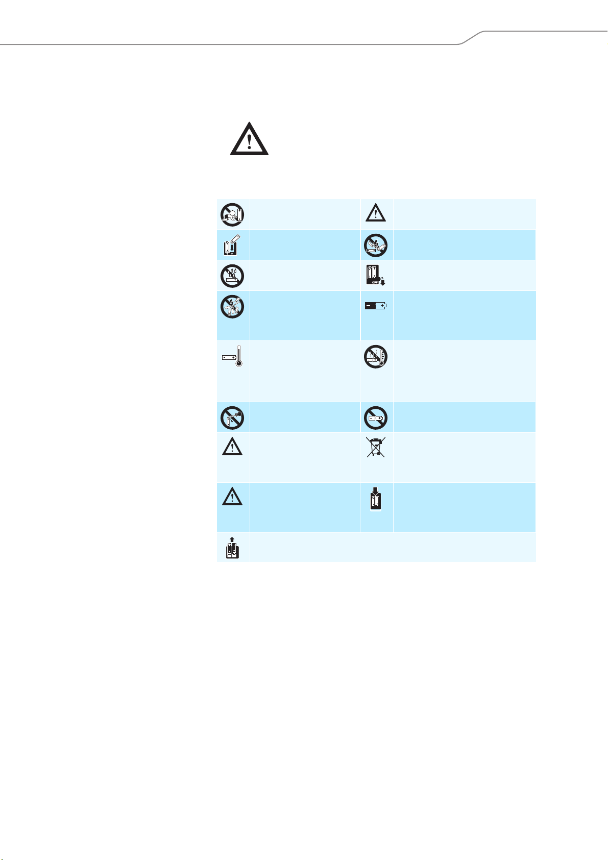
Safety instructions for NiMH rechargeable batteries
If abused or misused, rechargeable batteries may leak. In extreme cases, they may
even present
•a heat hazard,
•a fire hazard,
•an explosion hazard,
• a smoke or gas hazard.
Sennheiser does not accept any liability for damage arising from abuse or misuse.
Keep away from children. Only use rechargeable batteries
recommended by Sennheiser.
Observe correct polarity. Do not short-circuit.
Do not expose to moisture. Switch rechargeable battery-
powered products off after use.
Do not pack charged batteries loose – danger of
shorting out/fire hazard.
Only charge rechargeable
batteries at ambient
temperatures between
10°C/50°F and
40°C/104°F.
Do not mutilate or
dismantle.
Immediately remove
rechargeable batteries
from an obviously defective product.
Store the product in
a cool and dry place at
room temperature
(approx. 20°C/68°F).
Remove the rechargeable batteries if the product will not be used for
extended periods of time.
Intended use
When not using rechargeable batteries for extended periods of time,
charge them regularly (about every
three months).
Do not heat above 70°C/158°F,
e.g. do not expose to sunlight or
throw into a fire.
Do not continue to use defective
rechargeable batteries.
Dispose of rechargeable batteries
at special collection points or
return them to your specialist
dealer.
Only charge rechargeable batteries
with a charger recommended by
Sennheiser.
Intended use includes:
• using the products for professional purposes,
• having read and understood this instruction manual, especially the chapter
“Important safety instructions” on page 2,
• using the products within the operating conditions and limitations described in
this instruction manual.
“Improper use” means using the products other than as described in this instruction manual, or under operating conditions which differ from those described
herein.
Tourguide 1039 | 3
Page 5
The Tourguide 1039 system
2000 series
incl. IEM
evolution wireless G3
incl. IEM
MHz
Tourguide 1039
EK 1039 receiver
622-630
630-638
638-646
B
626-668 MHz
C
734-776 MHz
D
780-822 MHz
E
823-865 MHz
Dw
790-865 MHz
Cw
718-790 MHz
Bw
626-698 MHz
Dw
790-865 MHz
Cw
718-790 MHz
Bw
626-698 MHz
646-654
654-662
662-670
670-678
678-686
686-694
694-702
702-710
710-718
718-726
726-734
734-742
742-750
750-758
758-766
766-774
774-782
782-790
790-798
798-806
806-814
814-822
822-830
830-838
838-846
846-854
854-862
863-865
EK 1039
Ch 4
English
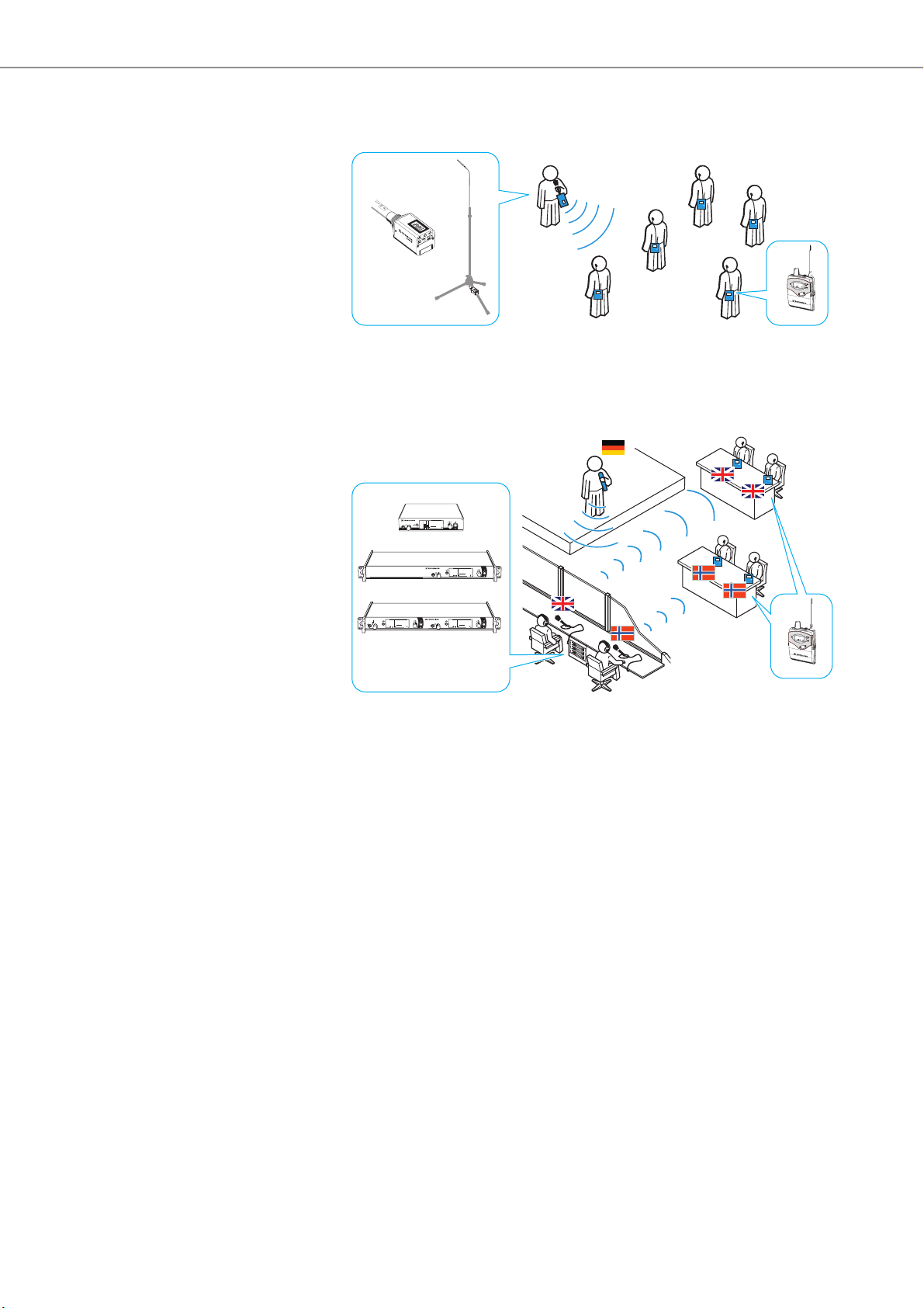
The Tourguide 1039 system
The Tourguide 1039 system consists of the EK 1039 receiver and a suitable transmitter of the evolution wireless G3 or 2000 series.
The system offers optimum speech transmission for guided tours, small conferences and interpretation applications with one or several speakers.
The use of RF transmission allows freedom of movement for all members of the
group. Due to the possibility of combining the EK 1039 receiver with different
transmitters, the system can be optimally adapted to your individual needs.
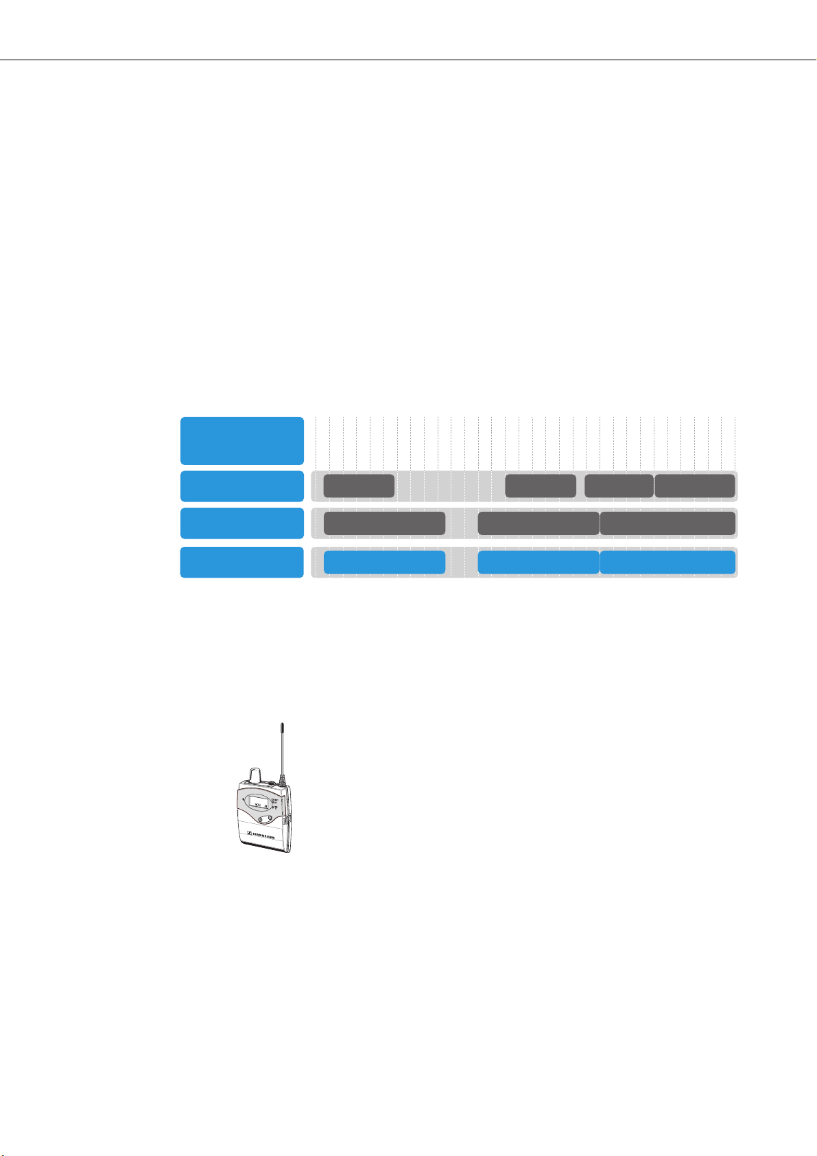
Frequency ranges
The EK 1039 receiver is available in the frequency ranges Bw, Cw and Dw. The following diagram shows an overview of compatible frequency ranges. For setting up
a transmission link, the evolution wireless G3 or 2000 (including IEM) series transmitter used must operate in a matching frequency range and must be set to the
same frequency as the receiver.
32 factory-preset frequencies that are intermodulation-free allow you to operate
up to 32 transmission links simultaneously.
You can change the factory-preset frequencies to s uit you r needs . In this case, however, it might be that the frequencies are not intermodulation-free.
Features of the EK 1039 receiver
The EK 1039 is a small, rugged bodypack receiver that can easily be attached to
clothing by means of a belt clip. The receiver allows you to connect any headphones
(min. 8 Ω) and to individually adjust the volume. 32 UHF receiving frequencies
(preset but changeable) offer high flexibility and adaptability.
Features of the receiver:
• Easy and comfortable use
• Channel indication with individual channel name via display
• Channel adjustment via rocker button
• Operation and reception indication via LED
•“LowBattery” indication via LED and display
4 |
Tourguide 1039
Page 6
The Tourguide 1039 system
SK
SKM
SKP
Stereo Transmitter SR 2000 IEM
P
EAK
-10
0
-20
-30
-40
PEAK
-10
0
-20
-30
-40
AF I
AF II
516.000
B.Ch: 1 1
EQ
Standard -18dB
MHz
**2000**
Stereo Transmitter SR 2050 IEM
PEAK
-10
0
-20
-30
-40
PEAK
-10
0
-20
-30
-40
AF I
AF II
516.000
B.Ch: 1 1
EQ
Standard -18dB
MHz
PEAK
-10
0
-20
-30
-40
PEAK
-10
0
-20
-30
-40
AF I
AF II
516.000
B.Ch: 1 1
EQ
Standard -18dB
MHz
**2050**
**2050**
531.375
ew300IEM
B.Ch: 20.24
EQ
Standard -18dB
MHz
Stereo Transmitter
PEAK
-30
-40
AF
0
-20
-30
-40
AF I
-30
-40
AF II
AF II
-10
SR
SR 300 IEM
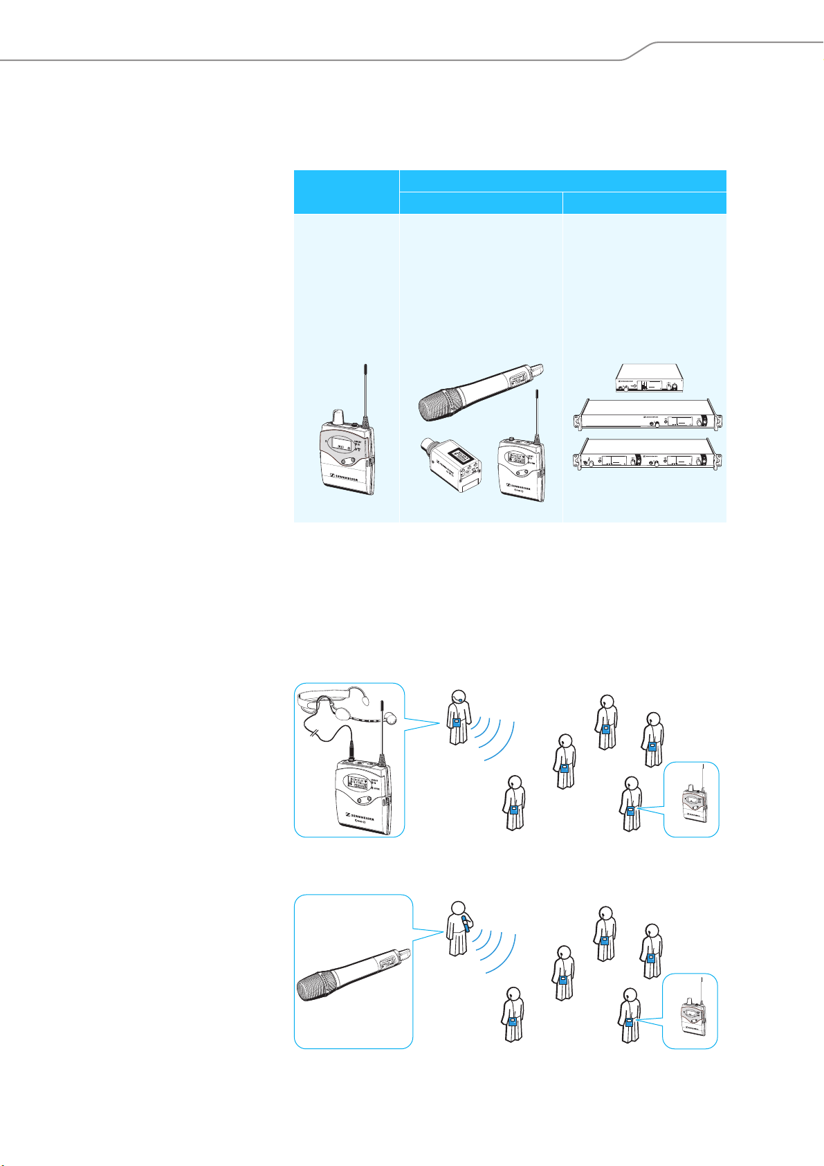
Suitable transmitters for your Tourguide application
The following table will help you to select a suitable transmitter for your Tourguide
application.
Receiver Transmitters
Mobile use Stationary use
Tourguide 1039:
• EK 1039
Ch 4
English
evolution wireless G3 series:
• SK 100/300/500
• SKM 100/300
• SKP 100/300
2000 series:
• SK 2000
• SKM 2000
• SKP 2000
evolution wireless G3 series:
• SR 300 IEM G3
2000 series:
• SR 2000 IEM
• SR 2050 IEM
EK 1039
All mentioned transmitters of the evolution wireless G3 or 2000 series are available in frequency ranges that are compatible with the frequency ranges of the
EK 1039 receivers (see page 4).
Mobile use of the transmitters
SK bodypack transmitter A portable bodypack transmitter allows the connection of a clip-on microphone or
a headmic so that the tour guide has both hands free and complete freedom of
movement while guiding the group.
e.g.
SK 300
EK 1039
SKM radio microphone A radio microphone can be passed on from the tour guide to members of the group,
e.g. when questions arise during the guided tour.
e.g. SKM 300
Tourguide 1039 | 5
EK 1039
Page 7
The Tourguide 1039 system
SKP plug-on transmitter A plug-on transmitter converts a wired microphone into a radio microphone,
SR monitoring transmitter You can use a stationary transmitter for e.g. running a small conference or for
allowing e.g. to use an existing microphone for your mobile Tourguide application.
e.g. SKP 300
with ME 36
EK 1039
Stationary use of the transmitters
offering a translation of the audio channel. The transmitter can be connected to
a mixing console and to other audio sources.
PEAK
B.Ch: 20.24
Stereo Transmitter
0
-10
-20
-30
-30
EQ
-40
-40
AF
AF II
AF II
AF I
SR 300 IEM
Stereo Transmitter SR 2000 IEM
SR 2000 IEM
PEAK
PEAK
**2050**
B.Ch: 1 1
Stereo Transmitter SR 2050 IEM
0
0
-10
-10
MHz
516.000
-20
-20
-30
-30
EQ
-40
-40
Standard -18dB
AF I
AF II
SR 2050 IEM
-30
-40
SR 300 IEM
ew300IEM
MHz
531.375
Standard -18dB
PEAK
PEAK
B.Ch: 1 1
**2000**
0
0
-10
-10
MHz
516.000
-20
-20
-30
-30
EQ
-40
-40
Standard -18dB
AF I
AF II
PEAK
PEAK
**2050**
B.Ch: 1 1
0
0
-10
-10
MHz
516.000
-20
-20
-30
-30
EQ
-40
-40
Standard -18dB
AF I
AF II
EK 1039
6 |
Tourguide 1039
Page 8
The Tourguide 1039 system
BA 2015
L 2015
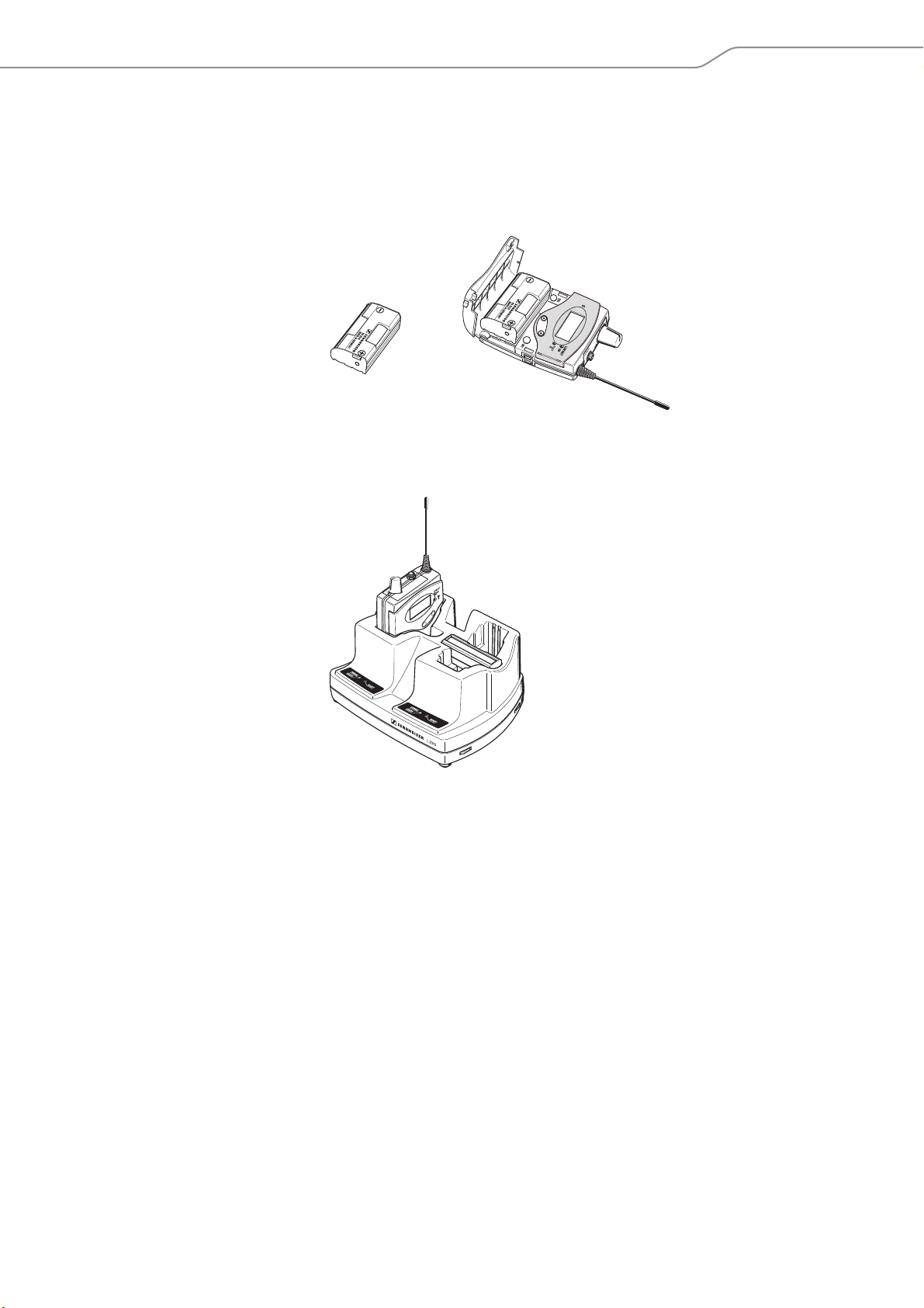
Charger for your Tourguide application
BA 2015 accupack
For daily use, we recommend using the supplied BA 2015 accupack. The accupack
can be charged in the L 2015 charger without having to be removed from the
device.
L 2015 charger
The L 2015 charger can charge up to two BA 2015 accupacks. The accupacks can be
charged separately or when installed in the receiver.
Tourguide 1039 | 7
Page 9
Product overview of the EK 1039 receiver
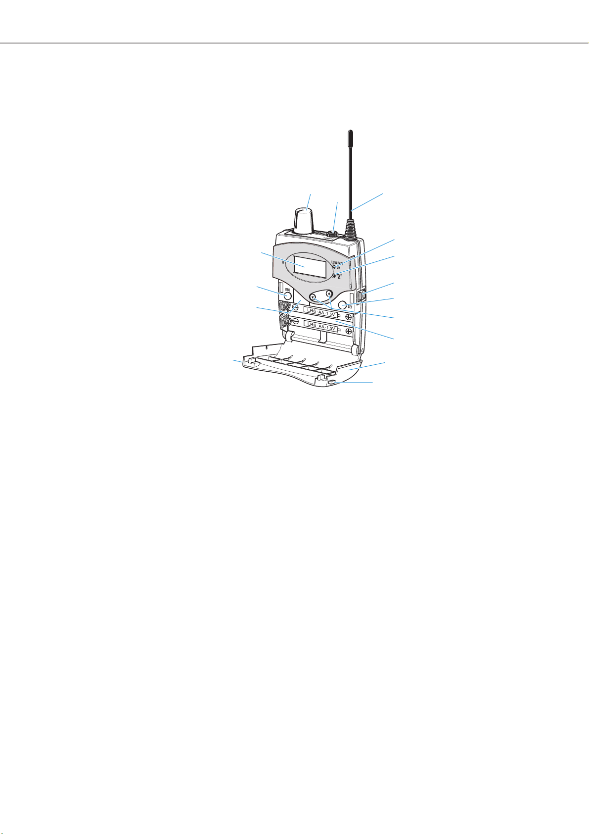
Product overview of the EK 1039
receiver
1 On/off/volume control
2 3.5 mm jack socket for headphones,
lockable
3 Receiving antenna
4 Operation and battery status
indicator “LOW BATT/ON”,
red LED:
lit = ON
flashing = LOW BATT
5 RF signal indication, green LED
6 Charging contacts
7 SET button
8 왖/왔 button (UP/DOWN)
9 Battery compartment
0 Battery compartment cover (metal)
A Battery compartment catches
B Infra-red interface
C ESC button
D Display panel, backlit in orange
8 |
Tourguide 1039
Page 10

Product overview of the EK 1039 receiver
Ch 4
English
Setup
Overview of the displays
After switch-on, the receiver displays the standard display:
The display backlighting is automatically reduced after approx. 20 seconds.
Display Meaning
E Receiving channel Current receiving channel “Ch 1” ... “Ch 32”
F Channel name Name of the receiving channel, individually adjustable;
G Lock mode icon Lock mode is activated (see page 12)
H Charge status
of the BA 2015
accupack/batteries
can consist of 8 characters max., e.g. “English”
Charge status:
approx. 100%
approx. 70%
approx. 30%
critical charge status,
the red LOW BATT LED
4 is flashing:
Ch 4
English
When you call up the menu for configuring the receiver (see page 14), the
receiver’s display panel shows the Setup display:
Tourguide 1039 | 9
Page 11

Putting the receiver into operation
Ch 4
English
Putting the receiver into operation
Inserting the batteries or the accupack
For powering the diversity receiver, you can either use two 1.5 V AA size batteries
or the rechargeable Sennheiser BA 2015 accupack.
For daily use, we recommend using the supplied BA 2015 accupack. The accupack
can be charged in the L 2015 charger without having to be removed from the
device.
왘 Open the battery compartment by pushing the two catches
of the arrows and open the cover 0.
A in the direction
왘 Insert the BA 2015 accupack or the two batteries as shown above. Please
observe correct polarity when inserting the accupack/batteries.
왘 Close the battery compartment by pressing on the center of the cover
battery compartment cover 0 locks into place with an audible click.
0. The
Charging the accupack
To charge the BA 2015 accupack installed in the receiver:
왘 Insert the diversity receiver into the L 2015 charger.
The receiver switches off and the accupack is being charged.
For more information on charging the BA 2015 accupack, refer to the instruction
manual for the L 2015 charger.
Never switch on the receiver during charging because otherwise the accupack will not be charged correctly.
The L 2015 charger can only charge the BA 2015 accupack. Standard batteries (primary cells) installed in the receiver or individual rechargeable
battery cells cannot be charged.
Connecting headphones
왘 Connect headphones with an impedance of at least 8 Ω to the 3.5 mm jack
2.
socket
10 |
Tourguide 1039
Page 12

Using the receiver
Ch 4
English
Using the receiver
To establish a transmission link between the configured transmitter and receiver,
proceed as follows:
1. Switch the receiver on (see next section).
2. Switch the transmitter on (see the instruction manual for the transmitter).
The transmission link is established and the receiver’s RF signal indication
lights up green.
For information on how to configure the receiver, read the chapter “Configuring the receiver” on page 14.
For information on how to configure the transmitter, read the chapter
“Configuring the transmitters for your Tourguide application” on page 22
and the instruction manual for the transmitter used.
If you cannot establish a transmission link between transmitter and receiver, read
the chapter “If a problem occurs ...” on page 23.
Switching the diversity receiver on/off and adjusting the volume
5
After switch-on, the receiver displays the standard display which allows the user to
switch between the receiving channels (see page 12).
You can configure the receiver via the Setup menu which you can access using
a special key combination during switch-on (see page 14).
To switch the receiver on:
왘 Turn the volume control
The red LED ON 4 lights up. The standard display appears on the display panel.
To switch the receiver off:
왘 Turn the volume control
The red LED ON
When not using the receiver for extended periods of time, remove the
accupack/batteries.
When you insert a switched-on receiver into the L 2015 charger, the
receiver automatically switches off. The receiver remains switched off
when you take it from the charger after charging. You first have to turn
the volume control
the receiver on (turn the volume control
4 goes off and the receiver switches off.
1 clockwise until it clicks.
1 counterclockwise until it clicks.
1 counterclockwise until it clicks to be able to switch
1 clockwise until it clicks).
Tourguide 1039 | 11
Page 13

Using the receiver
Ch 4
English
SET
To adjust the volume:
WARNING
Hearing damage due to high volumes!
Listening at high volume levels for long periods can lead to permanent hearing defects.
왘 Set the volume to a low level before using the product.
왘 Do not continuously expose yourself to high volumes.
왘 Turn the volume control
– clockwise to increase the volume
– counterclockwise to reduce the volume.
Using the “Limiter” function, you can reduce the audio level of the headphone output (see page 18).
1
Deactivating the lock mode temporarily
If the automatic lock mode “Auto Lock” is activated (see page 17), you have to
temporarily deactivate it in order to be able to operate the receiver:
왘 Press the SET button.
“Locked” appears on the display pane.
왘 Press the rocker button.
“Unlock?” appears on the display panel.
SET
The lock mode icon G flashes prior to the lock mode being activated again (if no
button has been pressed for approx. 10 seconds).
왘 Press the SET button.
The lock mode is deactivated.
Setting the receiving channel
If several guided tours take place within a building at the same time, i.e. several
transmission links are operated simultaneously, the user can switch the channel of
the receiver to the channel that is stated by the tour guide.
To switch between the receiving channels:
왘 Press the rocker button.
The receiver immediately switches to the new receiving channel. If the
receiver receives a transmitter on the new channel, the green LED
lights up.
The “Active” function allows you to show or hide the receiving channels
from the standard display (see page 20).
5
12 |
Tourguide 1039
Page 14

Using the receiver
Attaching the receiver to clothing
You can use the belt clip E to attach the diversity receiver to clothing (e.g. belt,
waistband).
The belt clip is detachable so that you can also attach the receiver with the antenna
pointing downwards. To do so, withdraw the belt clip from its fixing points and
attach it the other way round. The belt clip is secured so that it cannot slide out of
its fixing points accidentally.
To detach the belt clip:
왘 Lift one side of the belt clip as shown in the diagram.
왘 Press down the belt clip at one fixing point and pull it out of the receiver
housing.
왘 Repeat for the other side.
Tourguide 1039 | 13
Page 15

Configuring the receiver
Configuring the receiver
Calling up/ending the menu
You can only call up the menu when the receiver is switched off.
왘 Press the ESC button
왘 Turn the volume control
The Setup display appears on the display panel.
To end the menu:
왘 Switch the receiver off (see page 11).
When switching the receiver on again, the standard display will be shown.
C and keep it pressed.
1 clockwise until it clicks to switch the receiver on.
14 |
Tourguide 1039
Page 16

Configuring the receiver
ESC
Overview of the menu
”Setup“ menu
Auto Lock
Channels
Squelch
”Channels“ menu
Limiter
LCD Contrast
Software Revision
Copy
Exit
Display Function of the menu item Page
“Setup” menu
Auto Lock Activates the automatic lock mode 17
Channels Call up the “Channels” menu 19
Squelch Adjusts the squelch threshold 17
Limiter Activating the limiter of the headphone output 18
LCD Contrast Adjusts the contrast of the display panel 18
Software Revision Displays the current software version 18
Copy Copies receiver settings to additional receivers 18
Exit Exits the menu and returns to the Setup display –
“Channels” menu
Setup Ch 1 ...
Setup Ch 32
“Setup Ch 1” ... “Setup Ch 32” menu
Name Enters a freely selectable name for the channel 19
Tune Changes the receiving frequencies of the channels 20
Active Hides the receiving channel for the user 20
Exit Exits the “Setup Ch 1” ... “Setup Ch 32” menu and
Setup Ch 1
Setup Ch 2
...
Setup Ch 32
Calls up the “Setup Ch 1” ... “Setup Ch 32” menu 19
returns to the “Channels” menu
”Setup Ch 1“ …
“Setup Ch 32“ menu
Name
Tune
Active
Exit
–
The buttons
Button Function of the button
Press the
ESC button
Press the
SET button
SET
Press the
rocker
button
• Cancels the entry and returns to the Setup display (ESC function)
• Changes from the Setup display to the menu
• Calls up a menu item
• Enters a submenu
• Stores the settings
• Changes to the next/previous menu item
• Changes the setting of a menu item
Tourguide 1039 | 15
Page 17

Configuring the receiver
SET
Working with the menu
By way of example of the “Limiter” menu item, this section describes how to use
the menu.
Calling up the menu
왘 Press the SET button.
You call up the menu.
Selecting a menu item
왘 Press the rocker button to change to the “Limiter” menu item.
The current setting of the menu item is displayed:
Setup
Limiter
Off
Calling up a menu item and adjusting and storing it
Setup
Limiter
Off
Call up “Limiter”
SET
Limiter
Select the desired
setting
“Stored”
Off On
Limiter
Store the setting
SET
SET
왘 Press the SET button to call up the menu item.
왘 Press the rocker button to adjust the “Limiter” setting.
SET
왘 Press the SET button to store the setting.
Canceling an entry
ESC
왘 Press the ESC button to cancel the entry.
The Setup display appears on the display panel.
To subsequently return to the last edited menu item:
SET
왘 Press the SET button repeatedly until the last edited menu item
appears.
Returning to the next higher menu level or exiting the menu
To return to the next higher menu level:
왘 Change to the “Exit” menu item.
Setup Ch 4
Exit
SET
왘 Confirm your selection.
You return to the next higher menu level or exit the menu.
16 |
Tourguide 1039
To directly return to the Setup display:
ESC
왘 Press the ESC button.
Page 18

Configuring the receiver
Ch 4
English
Call up “Squelch” Select the desired
setting
Low
Squelch
Low
Squelch
High
Squelch
Setup
Store the setting
“Stored”
SET
SET
The “Setup” menu
Activating the automatic lock mode – “Auto Lock”
SET
Setup
Auto Lock
Inactive
Call up
“Auto Lock”
Possible settings: “Active”, “Inactive”
The automatic lock mode prevents that the receiving channel is accidentally
changed on the receiver. The lock mode icon
cates that the lock mode is activated.
For information on how to deactivate the lock mode, refer to page 12.
Adjusting the squelch threshold – “Squelch”
Auto Lock
Inactive
Select the desired
setting
“Stored”
Auto Lock
Active
Store the setting
SET
G on the standard display indi-
Possible settings: “Low”, “Middle”, “High”, “Off”
The squelch eliminates annoying noise when the transmitter is switched off or
when there is no longer sufficient transmitter power received by the receiver.
WARNING
Danger of hearing damage!
If you switch the squelch off or adjust the squelch threshold to a very
low value, loud hissing noise can occur in the receiver. The hissing
noise can be loud enough to cause hearing damage!
왘 Always make sure that the squelch is switched on.
왘 Before adjusting the squelch threshold, set the volume of the
headphone output to the minimum (see page 11).
왘 Never change the squelch threshold during a guided tour.
왘 Only switch off the squelch for servicing or test purposes.
왘 Adjust the squelch threshold – with the transmitter switched off – to the
lowest possible setting that suppresses hissing noise.
A high squelch threshold reduces the transmission range.
The squelch should only be switched off for servicing or test purposes. With the
squelch threshold set to “Low”, you switch the squelch off by keeping the DOWN
rocker button pressed for 3 seconds.
Tourguide 1039 | 17
Page 19

Configuring the receiver
Setup
Off
Limiter
Limiter
Limiter
Call up “Limiter”
Select the desired
setting
Store the setting
“Stored”
SET
SET
Off On
Call up “Copy”
Deactivates the function
Data transfer function
“Copy” is active
Copy
Setup
SET
SET
Copy
Activating the limiter of the headphone output – “Limiter”
Possible settings: “On”, “Off”
The limiter reduces the maximum volume at the headphone output by –12 dB.
Upon delivery, the “Limiter” function is switched on. We recommend to
keep this function switched on at all times.
Adjusting the contrast of the display panel – “LCD Contrast”
Setup
Name
LCD Contrast
Call up
“LCD Contrast”
7
LCD Contrast
7
Select the desired
setting
“Stored”
LCD Contrast
10
Store the setting
You can adjust the contrast of the display panel in 16 steps.
Displaying the software version – “Software Revision”
You can display the current software version of the receiver.
왘 For information on software updates, visit the EK 1039 product page at
www.sennheiser.com.
Copying the receiver settings to additional receivers – “Copy”
Via the “Copy” menu item, you can copy all settings of one receiver (A) to an arbitrary number of other EK 1039 receivers (B). This allows you to quickly and easily
transfer e.g. a new receiving channel to all other receivers in the system.
To prepare the receiver (A) to transfer the settings:
왘 Select a receiver.
왘 Set the desired receiving channel, the name, the squelch threshold, etc.
왘 Change to the “Copy” menu item.
All settings of this receiver (A) will be transferred to the other receivers (B).
To prepare the receivers (B) to receive the settings:
왘 Open the battery compartment cover of all receivers (B) to which you want to
transfer the settings.
왘 Switch on all receivers.
18 |
Tourguide 1039
Page 20

Configuring the receiver
A
B
max. 10 cm
Copy
햾
Call up
“Channels”
Select and call up
channel “1“ ... “32“
“Setup Ch 1” ...
“Setup Ch 32” menu
is reached
Setup
Channels
Channels
Setup Ch 2
Setup Ch 2
Name
To copy the settings:
왘 Place the receiver (A) above the infra-red interfaces
B of the other receivers
(B), one after the other. The distance between the infra-red interfaces must not
exceed 10 cm.
The settings are copied and “Copy” briefly appears on the display panels of the
receivers (B). If data transfer was successful, the receiver (B) switches off
automatically.
Strong extraneous light may interfere with the data transfer via the
infra-red interface. Therefore, position the receivers so that any possible
interference caused by extraneous light is avoided. The blue line between
the infra-red interfaces
B in the diagram on the left indicates the direc-
tion from which the IR radiation must impinge upon the receiver.
If you are using receivers from different frequency ranges and if you have
set a frequency that is not available in the frequency range of the receiver
(B), “Incompatible Frequency” appears on the display panel.
왘 Use receivers from the same frequency range or set a frequency that
is available in both frequency ranges.
The “Channels” menu
Calling up the “Setup Ch 1” ... “Setup Ch 32” menu
Via the “Channels” menu, you can call up the “Setup Ch 1” ... “Setup Ch 32”
submenu.
The “Setup Ch 1” ... “Setup Ch 32” menu
Entering a name – “Name”
Setup Ch 2
Name
Wnglish
Call up “Name” Enter a character
Name
W nglish
and confirm
“Stored”
Name
English
Enter a character;
store the setting
Via the “Name” menu, you can enter a freely selectable name for the receiving
channel (e.g. the language of the guided tour). The name is displayed on the standard display and can consist of up to 8 characters such as:
• letters (without pronounciation marks),
• numbers from 0 to 9,
• special characters and spaces.
To enter a name, proceed as follows:
SET
왘 Press the rocker button to select a character.
왘 Press the SET button to change to the next segment/character or to
store the complete entry.
Tourguide 1039 | 19
Page 21

Configuring the receiver
Select the MHz
value and confirm
Select the kHz value;
store the setting
Tune Tune
Call up “Tune”
Setup Ch 2
Tune
“Stored”
863.500 MHz
864.500 MHz
864.300 MHz
SET SET
SET
SET
SET
Changing the receiving frequencies of the channels – “Tune”
It is vital to observe the notes on frequency selection in the chapter
“Matching the transmitter to the receiver” on page 22.
Via the “Tune” menu item, you can change the receiving frequency of a channel.
The receiver’s channels have been factory-preset to receiving frequencies that
are intermodulation-free. However, you can change the factory-preset frequencies.
Within one frequency range, up to 32 transmission links can be operated
simultaneously.
To change the receiving frequency of the channel:
왘 Press the rocker button to adjust the frequency in MHz steps.
왘 Press the SET button to confirm the MHz setting of the frequency.
The kHz section of the frequency is highlighted.
왘 Press the rocker button to adjust the frequency in 25 kHz steps.
왘 Press the SET button to store the setting.
“Stored” appears on the display panel.
Adjusting the visibility of the receiving channel – “Active”
Setup Ch 2
Active
Call up “Active”
SET SET
Active Active
On Off
On
Adjust the visibility
and confirm
“Stored”
Store the setting
SET
Possible settings: activated and visible “On”, deactivated and hidden “Off”
Via the “Active” menu item, you can show or hide the receiving channel. An activated channel is visible on the standard display and can be selected. A deactivated
channel is invisible on the standard display and cannot be selected.
Tourguide 1039
20 |
Page 22

Cleaning and maintaining the receiver
Cleaning and maintaining the receiver
CAUTION
Liquids can damage the electronics of the product!
Liquids entering the housing of the product can cause a short-circuit and damage
the electronics. Solvents or cleansing agents can damage the surface of the
product.
왘 Keep all liquids away from the product.
왘 Do not use any solvents or cleansing agents.
왘 Use a dry cloth to clean the product from time to time.
Tourguide 1039 | 21
Page 23

Configuring the transmitters for your Tourguide application
Configuring the transmitters for your
Tourguide application
Please also read the instruction manual for your transmitter. It provides important
information that ensures safe and optimum operation of the transmitter in your
Tourguide application.
Matching the transmitter to the receiver
To be able to establish a transmission link, the transmitter and receiver
used must operate in compatible frequency ranges (see page 4) and must
be set to the same frequency.
Make sure that the desired frequencies are approved and legal in your
country and, if necessary, apply for an operating license.
You can contact your Sennheiser partner who will be pleased to calculate
intermodulation-free frequencies for you or to help you apply for an operating license.
SR
SKP
PEAK
PEAK
0
-10
-20
-30
-40
AF I
The receiver’s channels have been factory-preset to receiving frequencies that are
intermodulation-free (see frequency table on page 27). However, you can change
the factory-preset frequencies. Within one frequency range, up to 32 transmission
links can be operated simultaneously.
왘 Make sure to set the transmitter of the evolution wireless G3 or 2000 series to
the same frequency as the receiver.
If you still cannot establish a transmission link between transmitter and receiver,
read the chapter “If a problem occurs ...” on page 23.
Configuring the mobile SK, SKM and SKP transmitters
1. Set the frequency that you want to use for your Tourguide application (“Tune”
menu item).
SKM
2. Adjust the input sensitivity of the microphone (“Sensitivity” menu item; for
presentation applications, the guide values range from approx. –21 dB to
0dB).
SK
Configuring the stationary SR monitoring transmitter
-30
-40
SR 300 IEM
PEAK
ew300IEM
B.Ch: 20.24
Stereo Transmitter
0
-10
MHz
531.375
-20
-30
-30
EQ
-40
-40
Standard -18dB
AF
AF II
AF II
AF I
PEAK
PEAK
B.Ch: 1 1
**2000**
Stereo Transmitter SR 2000 IEM
0
0
-10
-10
MHz
516.000
-20
-20
-30
-30
EQ
-40
-40
Standard -18dB
AF I
AF II
PEAK
PEAK
**2050**
**2050**
B.Ch: 1 1
0
-10
MHz
516.000
-20
-30
EQ
-40
Standard -18dB
AF II
B.Ch: 1 1
Stereo Transmitter SR 2050 IEM
0
0
-10
-10
MHz
516.000
-20
-20
-30
-30
EQ
-40
-40
Standard -18dB
AF I
AF II
1. Set the frequency that you want to use for your Tourguide application (“Tune”
menu item).
2. Set the transmitter to mono operation to avoid interference during RF trans-
mission (“Mode” menu item).
3. Adjust the input sensitivity of the transmitter (“Sensitivity” menu item; for
presentation applications, the guide values range from approx. –21 dB to
0dB).
22 |
Tourguide 1039
Page 24

If a problem occurs ...
If a problem occurs ...
Problem Possible cause Possible solution
Receiver cannot be operated,
“Locked” appears on the display
panel
No operation indication Batteries are flat or
No RF signal Transmitter and receiver are not on
RF signal available, no audio signal Transmitter is muted (MUTE) Cancel the muting (see the instruction manual
Audio signal has a high level of
background noise
Audio signal is distorted Transmitter sensitivity is adjusted
No access to a certain receiving
channel
During copying, “Incompatible
Frequency” appears on the display
panel
Lock mode is activated Deactivate the lock mode (see page 12).
Replace the batteries or recharge the accupack
accupack is flat
Batteries are inserted the wrong
way round
the same channel
Transmission range is exceeded Reduce the distance between receiver and
Transmitter’s RF signal is deactivated (“RF Mute”)
Receiver’s squelch threshold is
adjusted too high
Microphone is defective Replace the microphone.
Headphones are defective Replace the headphones.
Transmitter sensitivity is adjusted
too low
too high
Receiver’s audio output level is
adjusted too high
Receiving channel is hidden for the
user
You are using receivers from different frequency ranges and you
have set a frequency that is not
available in the frequency range
of one of the receivers.
(see page 10).
Observe correct polarity when inserting the
batteries (see page 10).
Set the receiver and transmitter to the same
channel.
transmitter.
Check the squelch threshold setting and,
if necessary, reduce it (see page 17).
Increase the transmitter’s transmission power
(see the instruction manual for the
transmitter).
Activate the RF signal
(see the instruction manual for the
transmitter).
for the transmitter).
Reduce the squelch threshold setting
(see page 17).
Adjust the transmitter sensitivity correctly
(see the instruction manual for the
transmitter).
Adjust the transmitter sensitivity correctly
(see the instruction manual for the
transmitter).
Reduce the audio output level (see page 18).
Activate the visibility of the receiving channel
(“Active”, see page 20).
Use a receiver from the same frequency range.
Set a frequency that is available in both
frequency ranges.
Please also read the chapter “If a problem occurs ...” in the instruction manual for your transmitter.
If a problem occurs that is not listed in the above table or if the problem cannot be solved with the proposed solutions, please
contact your local Sennheiser partner for assistance.
To find a Sennheiser partner in your country, search at www.sennheiser.com under “Service & Support”.
Tourguide 1039 | 23
Page 25

Recommendations and tips
Recommendations and tips
General information
• Transmission range depends to a large extent on location and can vary from
about 10 m to about 150 m. There should be a “free line of sight” between
transmitter and receiver.
• For best sound quality, make sure that the transmitter sensitivity is correctly
adjusted (see the instruction manual for the transmitter).
… for SKM radio microphones and SKP plug-on transmitters
• Hold the radio microphone in the middle of the microphone body. Holding it
close to the sound inlet basket will influence the radio microphone’s pick-up
pattern, holding it at the lower part of the microphone body will reduce the
radiated transmission power and thus the transmission range.
• You can vary the bass reproduction by increasing/decreasing the talking
distance.
• For best sound quality, make sure that the transmitter sensitivity is correctly
adjusted (see the instruction manual for the transmitter).
• The plug-on transmitter uses the microphone body as an antenna – therefore
microphones with a metal casing should be used for best signal transmission.
… for SK bodypack transmitters
• Make sure that the antenna and the microphone cable do not cross.
• The antenna should hang or stand freely and be at least 1 cm away from the
body. The antenna must not be in direct contact with the skin.
• For best sound quality, make sure that the transmitter sensitivity is correctly
adjusted (see the instruction manual for the transmitter).
… for stationary SR monitoring transmitters
• Only use the monitoring transmitter in mono operation.
• For optimum RF operation, use suitable antennas from the Sennheiser accessory range. For more information on suitable accessories, visit the corresponding product pages at www.sennheiser.com.
24 |
Tourguide 1039
Page 26

Specifications
Specifications
The specifications of the transmitter can be found in the instruction
manual for the transmitter.
EK 1039 receiver
RF characteristics
Modulation wideband FM
Frequency ranges 626-698, 718-790, 790-865 MHz
(Bw, Cw, Dw see page 4)
Receiving frequencies max. 32, tuneable in steps of 25 kHz
Switching bandwidth ≤ 75 MHz
Nominal/peak deviation ±24 kHz / ±48 kHz
Receiver principle adaptive diversity
Sensitivity
(with HDX, peak deviation) < 4 μV, typ. < 1.6 μV for 52 dBA
Adjacent channel rejection typ. 80 dB
Intermodulation attenuation typ. 78 dB
Blocking ≥ 80 dB
Squelch Low: 5 dBμV, Middle: 15 dBμV, High: 25 dBμV
rms S/N
AF characteristics for headphone output
Compander system Sennheiser HDX
AF frequency response 40–15,000 Hz
S/N ratio
(1 mV
THD ≤ 0.9%
Headphone output 3.5 mm jack socket (mono, 2-pin,
Output power at 2.4 V, 5% THD
and nominal deviation 100 mW at 32 Ω
Adjustment range 42 dB (6 dB steps)
Overall device
Temperature range – 10°C to + 55°C
Power supply 2 AA size batteries, 1.5 V
Nominal voltage 2.4 V
Power consumption:
at nominal voltage
with switched-off receiver
Operating time with BA 2015 or
batteries
Dimensions approx. 81 x 65 x 23 mm
Weight (incl. batteries) approx. 200 g
, peak deviation) approx. 90 dBA
RF
for headphones with at least 8 Ω)
via potentiometer (+17 dBu reserve)
or BA 2015 accupack
typ. 140 mA (±5%)
≤ 25 μA
approx. 8 hrs
(depending on the volume set)
rms
Tourguide 1039 | 25
Page 27

Specifications
In compliance with
Europe EMC: EN 301489-1/-9
Radio: EN 300422-1/-2
Safety: EN 60065
Canada Industry Canada RSS-123
IC 2099A-EK1039
limited to 698 MHz
26 |
Tourguide 1039
Page 28

Appendix
Appendix
Radio frequencies
Channel
1 630.100 718.100 863.100
2 630.500 718.500 863.500
3 633.600 721.600 864.300
4 635.900 723.900 864.900
5 636.500 724.500 823.000
6 637.700 725.700 823.450
7 631.000 719.000 824.000
8 632.000 720.000 824.700
9 646.100 734.100 825.550
10 646.500 734.500 826.050
11 649.600 737.600 827.550
12 651.900 739.900 828.450
13 652.500 740.500 829.200
14 653.700 741.700 830.300
15 647.000 735.000 830.950
16 648.000 736.000 831.900
17 662.200 750.200 ...
18 662.600 750.600 ...
19 665.700 753.700 ...
20 668.000 756.000 ...
21 668.600 756.600 ...
22 669.800 757.800 ...
23 663.100 751.100 ...
24 664.100 752.100 ...
25 678.100 766.100 ...
26 678.500 766.500 ...
27 681.600 769.600 ...
28 683.900 771.900 ...
29 684.500 772.500 ...
30 685.700 773.700 ...
31 679.000 767.000 ...
32 680.000 768.000 ...
Frequency range
Bw (MHz) Cw (MHz) Dw (MHz)
Tourguide 1039 | 27
Page 29

Manufacturer Declarations
0682
Manufacturer Declarations
Warranty
Sennheiser electronic GmbH & Co. KG gives a warranty of 24 months on this product.
For the current warranty conditions, please visit our website at
www.sennheiser.com or contact your Sennheiser partner.
In compliance with the following requirements
• RoHS Directive (2002/95/EC)
• WEEE Directive (2002/96/EC)
Please dispose of the receiver at the end of its operational lifetime by taking it
to your local collection point or recycling center for such equipment.
• Battery Directive (2006/66/EC)
In order to protect the environment, the supplied batteries or rechargeable batteries can be recycled. Please dispose of them as special waste or return them
to your specialist dealer.
CE Declaration of Conformity
•
• R&TTE Directive (1999/5/EC)
• EMC Directive (2004/108/EC)
• Low Voltage Directive (2006/95/EC)
The declaration is available at www.sennheiser.com.
Before putting the product into operation, please observe the respective countryspecific regulations.
Statements regarding FCC and Industry Canada
This device complies with Part 15 of the FCC Rules and with RSS-123 of Industry
Canada. Operation is subject to the following two conditions: (1) this device may
not cause harmful interference, and (2) this device must accept any interference
received, including interference that may cause undesired operation.
This equipment has been tested and found to comply with the limits for a Class B
digital device, pursuant to Part 15 of the FCC Rules. These limits are designed to
provide reasonable protection against harmful interference in a residential installation. This equipment generates, uses and can radiate radio frequency energy and,
if not installed and used in accordance with the instructions, may cause harmful
interference to radio communications. However, there is no guarantee that interference will not occur in a particular installation. If this equipment does cause
harmful interference to radio or television reception, which can be determined by
turning the equipment off and on, the user is encouraged to try to correct the interference by one or more of the following measures:
• Reorient or relocate the receiving antenna.
• Increase the separation between the equipment and receiver.
• Connect the equipment into an outlet on a circuit different from that to which
the receiver is connected.
• Consult the dealer or an experienced radio/TV technician for help.
This class B digital device complies with the Canadian ICES-003.
Changes or modifications made to this equipment not expressly approved by
Sennheiser electronic Corp. may void the FCC authorization to operate this
equipment.
28 |
Tourguide 1039
Page 30

Sennheiser electronic GmbH & Co. KG
Am Labor 1, 30900 Wedemark, Germany
www.sennheiser.com
Publ. 01/12
 Loading...