

Page 1
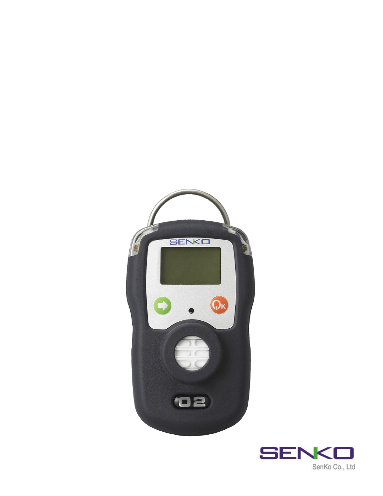
MODEL: SP2nd
(Portable Single Gas Detector)
Operating Manual
Version 2.2
Page 2

Product Introduction
SP2nd is Simple Gas Alarm Detector that is required to protect users’ safety at
dangerous work environments. The apparatus can indicate simultaneously the
concentration of gases (Oxygen, Carbon Monoxide, Hydrogen Sulfide, Hydrogen,
Sulfur Dioxide, Hydrogen Chloride, Ammonia and etc.) on a digital LCD monitor,
and the methods of operation and calibration are easy and convenient.
This instrument alerts accurately the alarm circumstances to operators and
workers for their safety with its functions of loud alarm sound and vibration,
when higher gas concentration than normality is detected. Besides, it is available
for users to check upon occasion and adjust the value of alarm to the work
environment on demand, since it has the function of indicating minimal and
maximal concentration of the gases. It is also possible to prevent in advance
workers from the danger of exposing for a definite period of time to such toxic
gases as Hydrogen Sulfide(H2S), Carbon Monoxide(CO) and Sulfur Dioxide(SO2)
by its function of STEL(Short Term Exposure Limit) and TWA(Time Weighted
Average).
Guarantee and Repair
Senko Co., Ltd. guarantees the products of SP series for 24 months from the
shipping date and repairs or replaces the defected product during warranty
period. Nevertheless, Senko is not responsible for the following cases and would
not repair or replace the product at no cost, such cases as the product has been
purchased through the route that Senko does not approve, or as the product
has been damaged or deformed mechanically by misuse of the user, or as the
product has not been calibrated or replaced the parts according to processes in
the operating manual.
In the event that any defect or issue of the product occurred during warranty
period, Senko will cover all the expenses except transportation fee. After the
period of warranty, the expenses of repair or replacement of the product and
transportation will be in principle borne by the user. Senko will not be
responsible for any indirect occurrence or accident and/or damage during the
use of the product, and the guarantee shall be limited to the replacement of
parts and product. The guarantee is applied only to the users who purchased
the product at Senko’s authorized dealers or agents, and the guarantied repair is
to be performed by the expert engineers of Senko’s authorized aftercare center.
01
Page 3

Contents of Operating Manual
Product Specification ---------------------------------- 03
Names of Exterior and Display ----------------------- 04
Start and End of Operation -------------------------- 05
Operation Method ------------------------------------- 06
Backlight ---------------------------------------------- 06
Data Log ---------------------------------------------- 07
Calibration ---------------------------------------------- 08
Day and Time ------------------------------------------ 10
Method of Alarm Set and Display ------------------- 11
Battery & Sensor replacement------------------------ 13
Applicable Battery and External Pump -------------- 14
Notice for User ----------------------------------------- 15
02
Page 4

1. Product Specification(SP2nd)
Model
SP2217 SP2227 SP2257 SP2277 SP2297 SP22L7 SP22N7 SP22C7
Measured
Gas
O
2
CO SO
2
H
2
H2S Cl
2
NH
3
NO
2
Measured
Range
0~30
%Vol
0~500
ppm
0~20
ppm
0~1000
ppm
0~100
ppm
0~20
ppm
0~100
ppm
0~20
ppm
Measurement
Method
Electrochemical Type
Principle of
Measurement
Diffusion Type
Monitor
LCD display (Built in back light)
Alarm
90dB
Alert Lamp
Red LED (Light-Emitting Diode)
Vibration
Alert
Vibration Alarm(Rated Speed : 6,000 ± 1,000RPM)
Power source
Applicable
Temperature
& Humidity
-20℃ ~ +50℃, : 5% ~ 95% RH (non-condensing)
Explosion-
Proof
Ex ia IIC T4 / IP67 (KGS, ATEX)
Case
Rubber PC Case
Standard
Accessories
Belt Clip, Calibration Cap
Optional
Accessories
Small-Sized Pump for Sampling(SP-Pump101)
Exterior
Dimension : 54mm(W) x 91mm(H) x 32 mm(D)
Weight :120g (Including Battery)
Event Log
Save the latest 20 data
03
Page 5
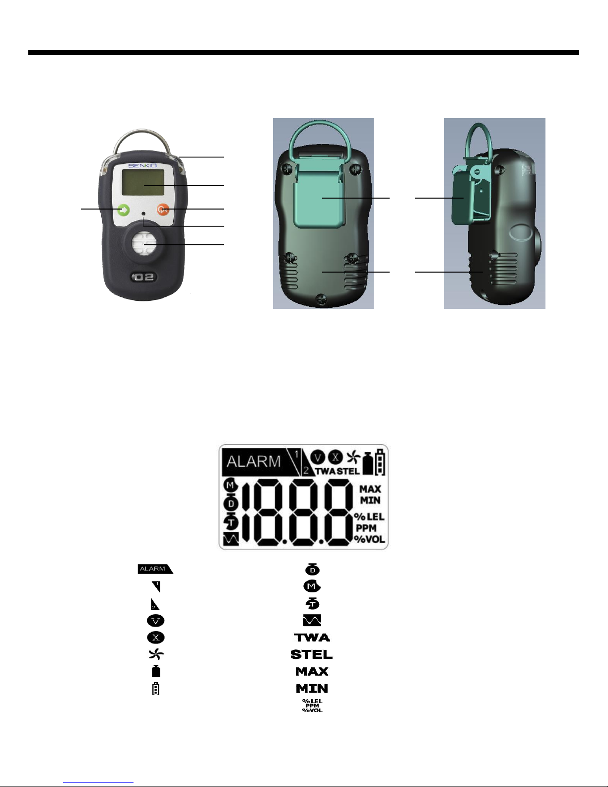
04
Alarm
First Alarm
Second Alarm
Safety Success
Safety Failure
Fresh Air Calibration
Single Gas Calibration
Battery
Time Average Level Alarm
Date
Time
Log Value
Max Peak Value
Unit
Month
Time Average Level Alarm
Min Peak Value
5
1
2
3
4
6
7
8
LCD display symbols
2. Names and Functions of Exterior
1. Gas sensor
2. Buzzer
3. LCD display
4. Power Key
5. Arrow Key
6. Alarm LED
7. Fastening clip
8. Type label
Page 6
05
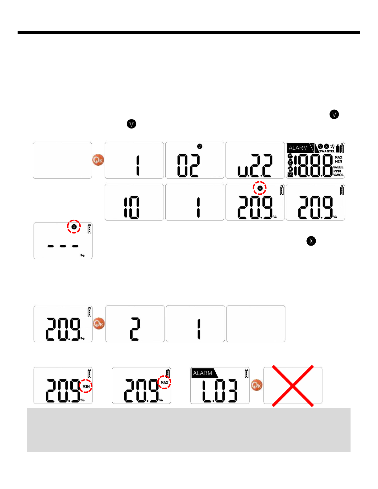
3. Start and End of Operation
Instrument Power-On
OFF
…
In the event that stabilization of the instrument fails, it would
not convert to Gas Detection Mode, blinking the mark . In this
case, calibration of the sensor or aftercare of the instrument is
required.
Instrument Power-Off
OFF
Press Power key for a few seconds then power is turned off displaying countdown
in order on the monitor.
or or
OFF
<Caution> Appropriate calibration of the instrument is always required prior to
the operation at work sites. Make sure if the instrument makes the proper
detection response to the pertinent gas and if the region of the gas detection is
not blocked with foreign materials that interfere with the gas detection.
Press Power key for a few seconds, and power is turned on. Measured gas and
version appear on the screen. Afterwards during the instrument is being stabilized,
the countdown appears on the screen. When the instrument is stabilized after the
display of the above set values, it converts to Gas Detection Mode displaying icon. At normal status, icon disappears after blinking several times, and the
concentration of the gas detected of the moment is indicated.
If power key is pressed at any mode except the Gas Detection Mode or power
key isn’t pressed for a few seconds, power isn’t turned on.
Page 7
06
4. Operation Method
Detection Mode
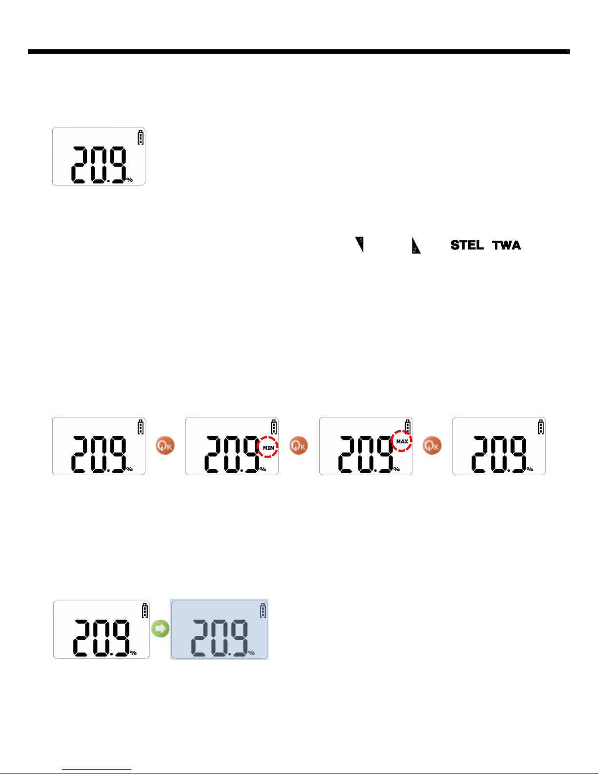
At the state of Gas Detection Mode indicating the concentration of gases simultaneously, LED Backlight is turned on by the
shor t press on Arrow key, that enables
the operator to view the measured value even at dark atmosphere. It is turned off
by pressing again once more. Backlight will be automatically turned off after
several seconds unless the button works.
The instrument is converted to Gas Measure Mode as below,
when power is turned on. Gas Measure Mode indicates the
concentration of gas and the remained capacity of battery on LCD,
and it displays the gas concentration of Oxygen by %, and such
toxic gases as H2S, CO and SO2 by ppm units.
In the event that the concentration of gas changes, it indicates the value of
concentration in real-time. If it exceeds the 1st Alarm(LO) or 2nd Alarm(HI)
standard (or STEL / TWA), the measured value and icon or icon( , icon
in case of STEL / TWA) blinks periodically with the alerts by alarm sound and
vibration. When the operator moves to the safe place where the concentration
value of the measured gas is the normal state, the concentration value reduces and
the alarm stops. (Even if the operator escapes to a safe area after the alarm alerts,
the icon of alarm remains on the screen, and it will disappear only after confirming
the value by pressing Power key. When the concentration value of the measured
gas exceeds the maximum measuring range, it is indicated as the maximum value.
And LED, alarm sound and vibration applicable to 2nd Alarm Standard operate
together.
Indication of Peak Value and TWA & STEL Value
At Gas Measure Mode, in case of Oxygen, the measured minimum and maximum
values are displayed in order. And in case of Toxic Gases, maximum value, STEL
value and TWA value are displayed consecutively. Program returns to Measure
Mode, when Power key is pressed at state displaying Peak, STEL and TWA. If the
button is not touched for several seconds, the program will return to Gas Measure
Mode.
5. LCD Backlight
Page 8
07
6. Data Log
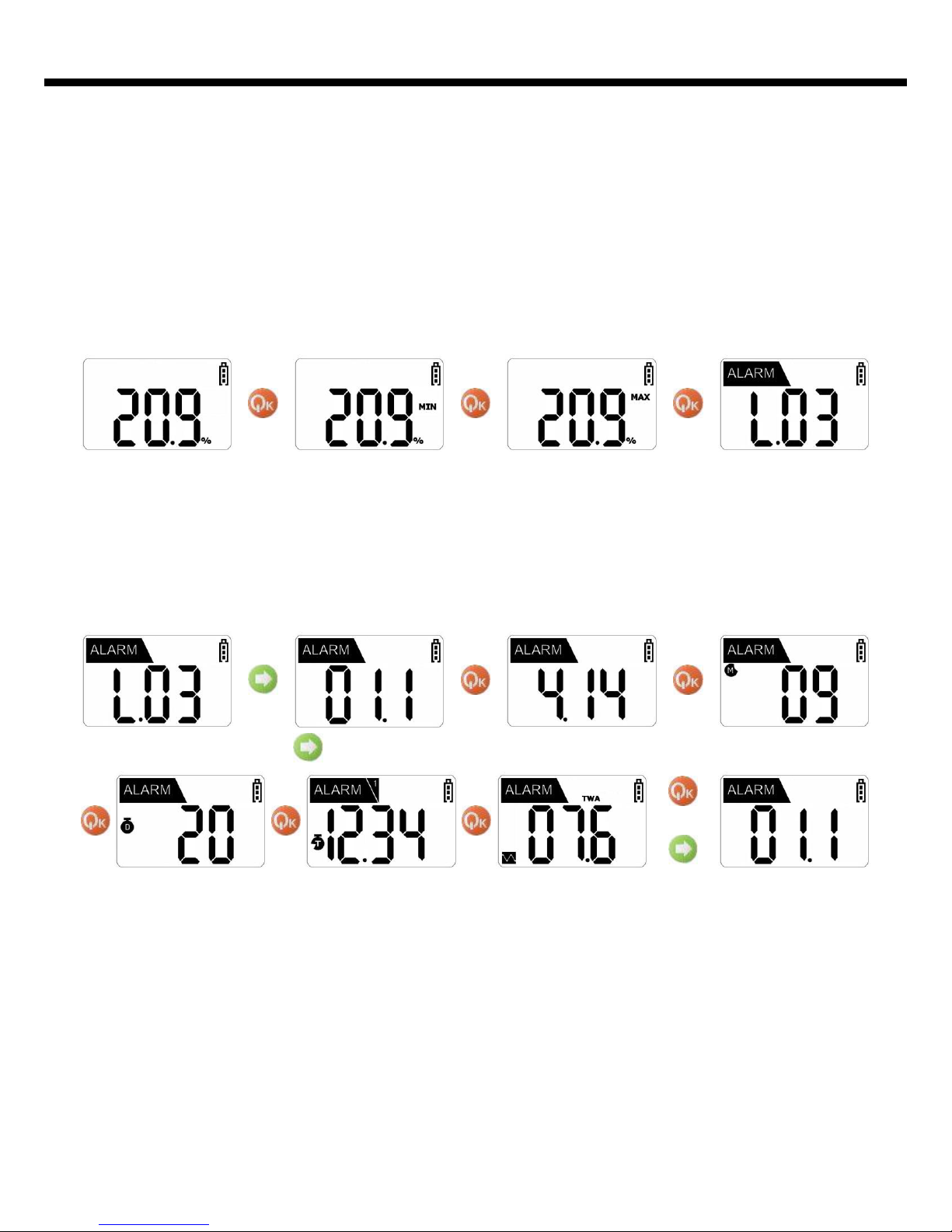
At Gas Detection Mode, whenever short press Power key once, Data Log Mode is
displayed after the measured minimum, maximum, STEL, TWA values are displayed
in order. In order word, press four time(In case of Oxygen, three time), Data Log
Mode is displayed.
‘L’ of ‘L.03’ means Log and ‘03’ means the number of date. Consequently, the
program is saved three data.
At Data Select Mode ‘01.1’, left number ‘01’ means data and right number ‘1’
means occurred alarm(‘1’ is 1st alarm or ‘2’ is 2st alarm). In order word, first data of
saved three data means occurred 1st alarm value. If another data is confirmed, data
is selected by pressing Arrow key. Also if Arrow key is pressed at final data,
program returns to Gas Measure Mode.
Data is saved to twenty number and if the number of data is over twenty, data is
removed automatically in order of data that is stored the in the beginning
or
Select Data
Data Select Mode is displayed by pressing Arrow key. At this mode, data is
selected and a record is confirmed. Again press Power key once, year, month, day,
time and alarm recorded are confirmed. If Arrow key is pressed at year, month, day,
time display, the program returns to Data Select Mode.
Alarm Data
Page 9
08
7. Calibration
<Caution> Senko Co., Ltd. performs the initial calibration before the shipment.
Incorrectly calibrated value can reduce the accuracy of the product, as the calibrate
d value is stored in the instrument. Calibration is in general to be performed
monthly or quarterly, and can be adjusted according to frequency of the use.
Start Fresh air
Calibration
Start Standard
Gas Calibration
<Caution> Fresh Gas Calibration should be performed at the environment of fresh
air without any influence of other gases, since the calibration is performed on the
assumption that the concentration of Oxygen is 20.9%, that of Inflammable Gas is
0%LEL, and the concentration of Toxic Gas is 0ppm in the fresh air. Accordingly it
is not recommended to perform Fresh Air Calibration at the closed space, and it
should be avoided to perform the calibration where gases can be inhaled by
operators.
…
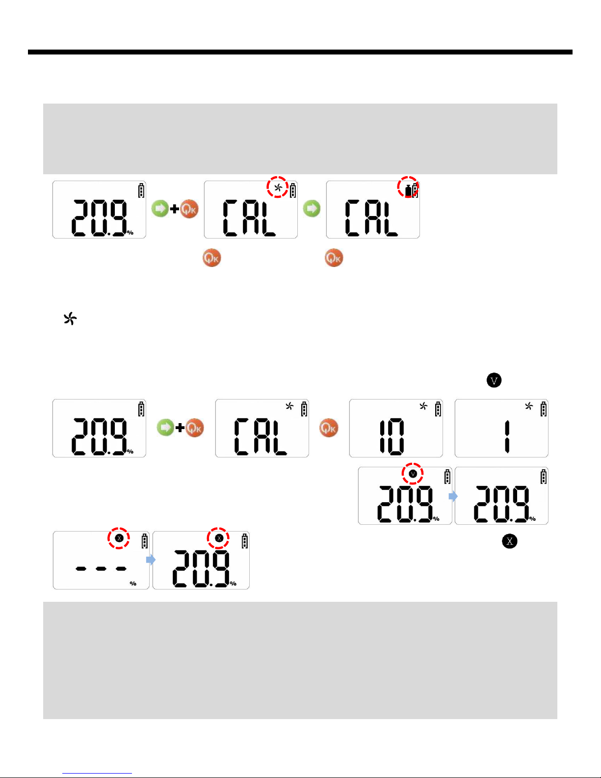
If Standby State Calibration failed, icon
appears continuously. If this occurrence repeats,
please consult a dealer or aftercare center to
replace the sensor.
Fresh air Calibration
icon appears when Power key is pressed a few seconds at the state of
pressing Arrow key simultaneously. Program will enter to Calibration Mode of
Standby State. When Calibration starts, countdown 10, 9, 8………….3, 2, 1 continues
for 10 seconds and Calibration will be completed. If Calibration is completed
normally, it returns to Gas Measure Mode after several times blinking of icon
Page 10
09
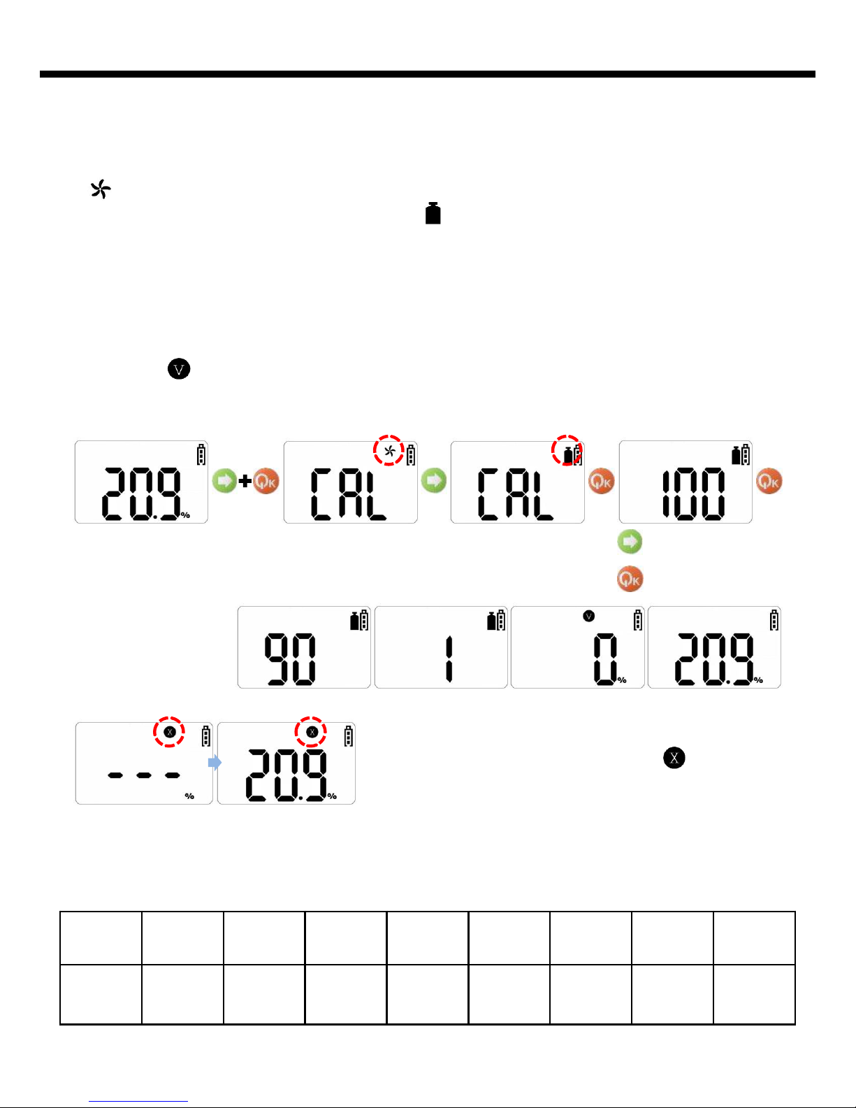
Standard Gas Calibration
If the Calibration fails, program returns to Gas
Measure Mode after displaying of icon. If this
occurrence repeats, please consult a dealer or
aftercare center to replace the sensor.
…
Change Value
Save Value &
Start Calibration
Gas O
2
CO SO
2
H
2
H2S Cl
2
NH
3
NO
2
농도 0%
100
ppm
10
ppm
500
ppm
50
ppm
10
ppm
50
ppm
10
ppm
Concentration of Calibration Gas Set to Instrument
icon appears when Power key is pressed a few seconds at the state of
pushing Arrow key simultaneously. And icon appears by input of Arrow key at
the state. Standard Gas Calibration starts by pressing Power key for a few seconds
displaying countdown. Be careful not to proceed with Calibration at the state
without connecting with Standard Gas.
When Standard Gas Calibration starts, in case of Oxygen, Calibration proceeds by
the countdown for 90 seconds. If the Calibration is normally executed, the
concentration value of the gas connected at the moment is indicated with
displaying icon. Afterwards, it indicates the concentration value measured at the
moment, when Standard Gas is disconnected.
Page 11
10
8. Date and Time
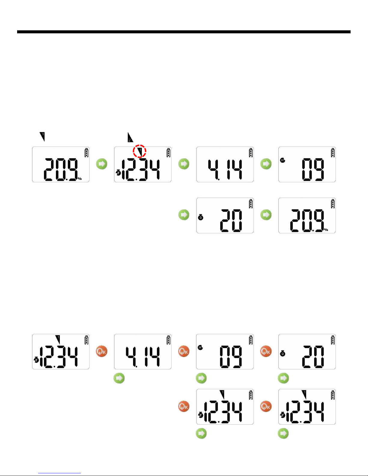
At Gas Detection Mode, press Arrow key for three seconds, Date and Time View
Mode is displayed. At this moment, press Power key for five seconds. Then the
Date and Time Set Mode is displayed and number flickers. Press Arrow key, change
value(Press long Arrow key, increase value quickly) and press Power key, save value.
Year set up to 2030 maximum. When using product early, user must set exact date
and time because of not doing ship setting exact date and time
20th
AM 12:34 September 2014
Date and Time Set
Change hour Change minute
Change year Change month Change day
At Gas Detection Mode, press Arrow key for three seconds, Date and Time View
Mode is displayed. At this moment, short press Arrow key. Then the present time,
year, month, day are confirmed with icon or character equivalent to it. If Power key
is at the Present Mode or key is not pressed for several seconds, the program will
return to Gas Measure Mode.
icon means AM, and icon means FM at the Present Time.
Date and Time View
Page 12
11
9. Method of Alarm Set and Display
Alarm Set
<Caution> The value of alarm of the instrument is set according to the alarm
standard of each gas that is required by international standard. Therefore alarm
value of the relevant gas can be changed under the responsibility and approval of
the administrator of the work site where the instrument is used.
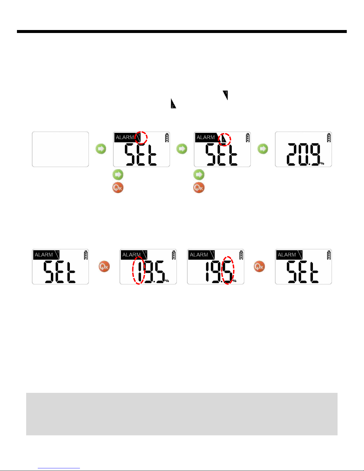
OFF
Change alarm
Save alarm
Change alarm
Save alarm
Press Power key at Alarm Set Mode, alarm value is checked. Using Arrow key,
change alarm value and using Power key, save alarm value or move number. After final
digit changes, press Power key once, program returns to Alarm Set Mode
Press Arrow key at 1st Alarm Set Mode, mode changes 2nd Alarm Set Mode or Gas
Measure Mode. 2nd alarm set method equals 1st alarm set method.
Alarm Display
When the 1st alarm occurs, and the operator recognizes it and presses Power key,
only the alarm sound stops, remaining LED alarm as the operation stale. When the
2nd alarm happens, the operator and workers should promptly escape from the
work site. The alarm do not even stop where the concentration value of gas is
normal.(It need to turn off/on to stop all alarms.)
When STEL / TWA alarm occurs, it is indicated with the value of the measured
concentration and alerts alarms of the same sound of alarm and vibration as that
of the 2nd alarm. When STEL / TWA alarm occurs, the icon can be deleted only by
Power Off.
…
When Arrow key is pressed for a few seconds at the state of power off, program
enters to 1st Alarm Set Mode with displaying of icon. In this moment, 2nd
Alarm(HI) Set Mode with displaying icon by pressing Arrow key. Press Arrow
key one more, display returns to Gas Measure Mode without changing Alarm Set
value.
Page 13
12
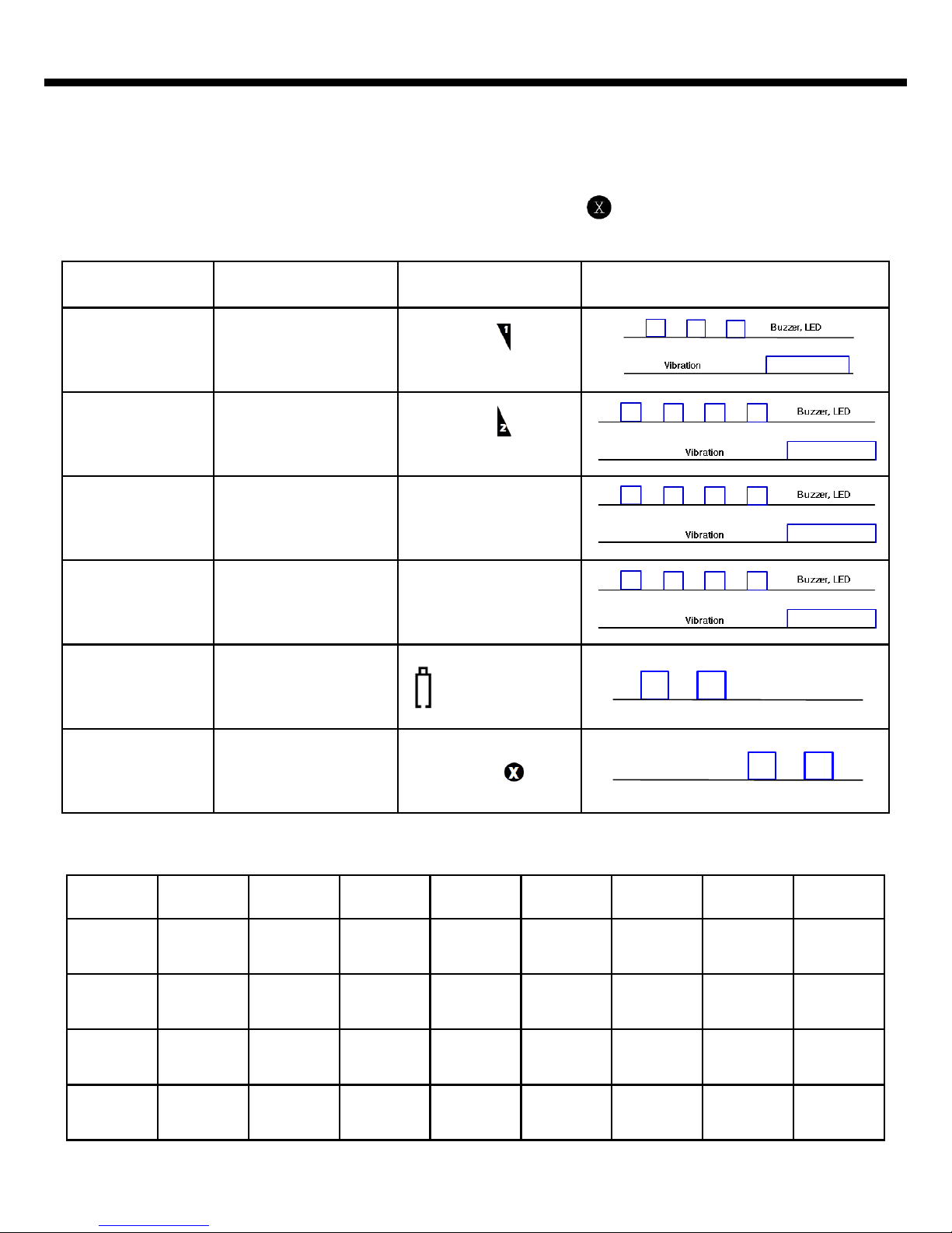
Alarm Alarm Standard LCD Display Alarm & Vibration Display
1st Alarm
In Exceeding Alarm
Value Set Primarily
Displaying Icon &
Concentration
2nd Alarm
In Exceeding Alarm
Value Set Secondarily
Displaying Icon &
Concentration
TWA
In Exceeding Exposure
Concentration for 8
hour
Displaying Icon TWA &
Concentration
STEL
In Exceeding Exposure
Concentration for
15 minutes
Displaying Icon STEL
& Concentration
Dead Battery
Battery Capacity is
Exhausted.
Blinking of Battery
Test Failure
Failure of Sensor Test
Failure of Calibration
Displaying Icon
Buzzer, LED,
LCD Backlight
Buzzer, LED
Alarm Set Point
Gas O
2
CO SO
2
H
2
H2S Cl
2
NH
3
NO
2
1st
19% 30ppm 2ppm 100ppm 10ppm 0.5ppm 25ppm 3ppm
2nd
23% 60ppm 5ppm 500ppm 20ppm 1ppm 35ppm 5ppm
TWA
N/A 30ppm 2ppm N/A 10ppm 0.5 pm 25ppm 3ppm
STEL
N/A 200ppm 5ppm N/A 15ppm 1ppm 35ppm 5ppm
Primary battery alarm sounds repeatedly at 5 minute intervals when only a bar of
battery icon is remained. Secondary battery alarm starts right before the end of
power, and the power source finishes after 10 seconds from the outbreak of alarm.
In the event of failure of test or calibration, the icon is displayed with the
sound of alarm.
Page 14
13
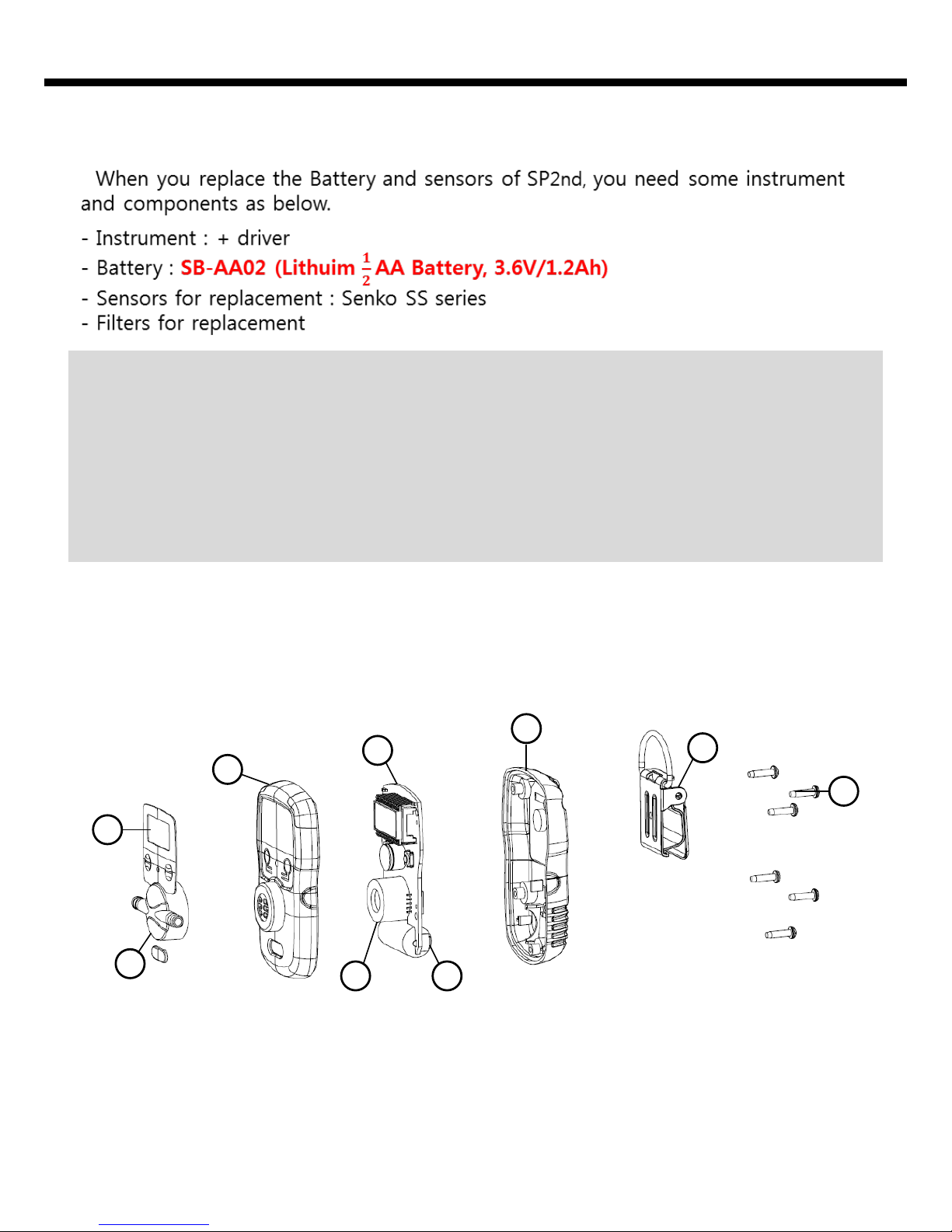
10. Battery & Sensor replacement
- Turn off the power.
- Replace the sensor and battery , please refer to below drawing.
- After replacement, check the sensor fail and battery working.
Disassembly
<Caution>
1. It is absolutely prohibited to replace battery at potential explosion or dangerous
regions.
2. Replacement of components can be damage to intrinsic safety function.
3. The sensors published by SENKO should be used for replacement. Unsuitable
function could be shown if another sensors use for replacement.
4. Disassembly should be necessary only for sensors & battery replacement. After
the sensor replacement, the span gas calibration should be done.
2
1
3
4
5
7
6
8
9
1. Label(Membrane)
2. Calibration Cap
3. Front Cover
4. Sensor
5. PCB
6. Battery
7. Rear Cover
8. Belt clip
9. Machine Screw
Page 15
14
11. Applicable Battery and External Pump
<Caution> Explosion can occur, when a battery is thrown into fire or disassembled
with force. Disposal of the used battery should be performed according to the
guide of the pertinent country or the work site.
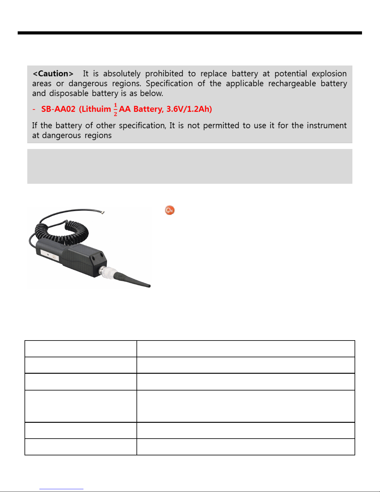
Accessory(Optional) - External Pump (SP-Pump101)s
Product specification(SP-Pump101)
key has the function of On/Off, and the state
of operation or trouble of the instrument can be
recognized by LED lamp. When the leakage
measurement or the measurement of concentration by inhalation of gas is required, it is
available to measure gas concentration and
leakage at the pertinent place by connecting the
pump to the instrument. Prior to use, make sure
that the instrument is tightly attached to the
probe cover which is connected to the sensor.
**Please note that External Pump is the optional product that can be provided
by the separate order.
Power Source
AA Size Alkaline Battery(1 EA)
Continuous Operation Time
Available to Operate for 10 hours or longer
Applicable Temperature &
Humidity
-20°C ~ +50°C / 5 ~ 95% RH
Exterior
Dimension: 34mm(W) x 270mm(H) x 47 mm(D)
Weight: 200g (Including )
Sampling Flux
0.5 liter / minute
Diagnosis Function
Deadlock Alarm, Alert of Insufficient (Red LEC Display)
Page 16
Please use the instrument in the range of the applicable temperature, humidity and
pressure that are appropriate for the specification of the product. Using the
instrument beyond this range may cause malfunction or glitch of the instrument. .
12. Notice for User
Gas concentration measurement value by the sensor or the instrument can vary
according to the environment at site (temperature, pressure and humidity).
Therefore the calibration of the instrument should be performed at the same or
similar environment as that of the instrument use (temperature, pressure and
humidity).
If temperature changes sharply during use of the instrument (for instance, using
the instrument at places of far different temperatures between indoor and outdoor),
the value of the measured gas concentration can be changed suddenly. Please use
it after the gas concentration value is stabilized.
Severe vibration or shock to the instrument may cause the sudden change of value
of the measured gas concentration. Please use it after the value of gas
concentration is stabilized. Excessive shock to the unit can lead to trouble of the
sensor or the instrument.
15
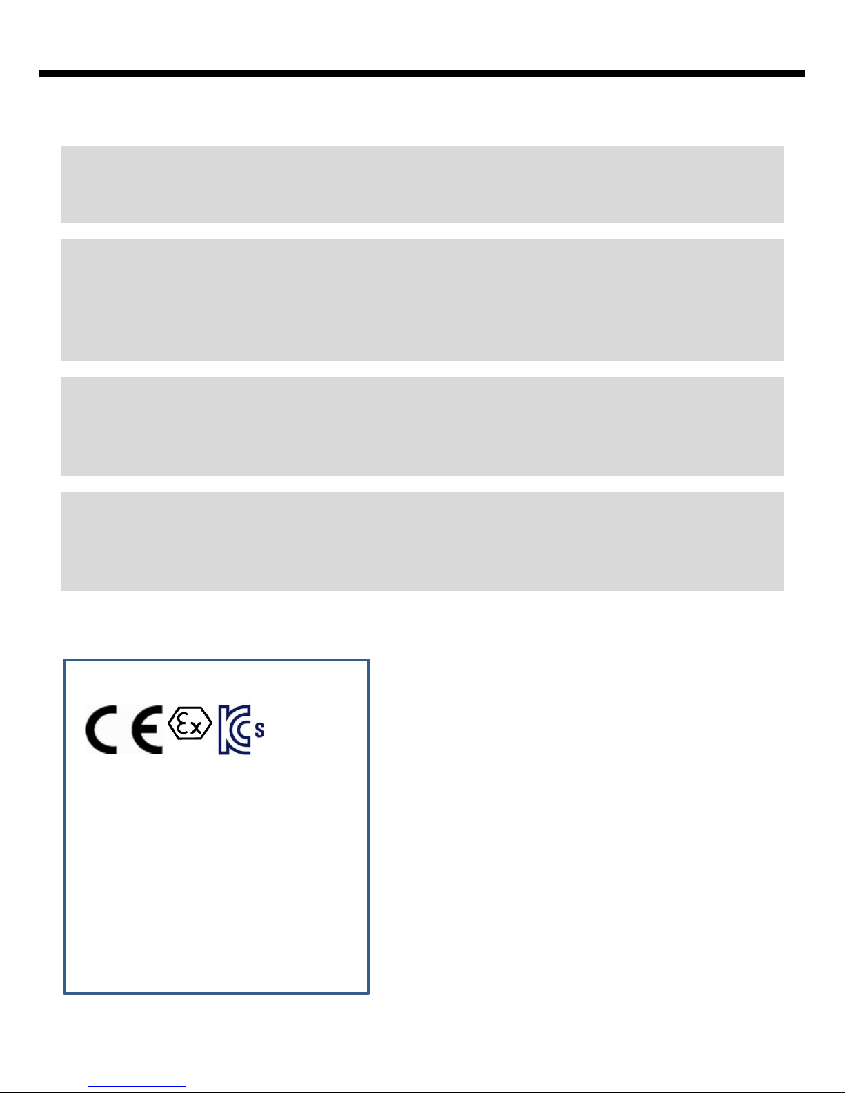
Notes on Approval(Label)
SENKO Type : SP2nd
Ex ia IIC T4 IP67
DNV 10 ATEX 74743
-20℃≤Ta≤+50℃
SENKO Co.,Ltd.
15 Road Oesammiro (485 Oesammi-dong),
Osan-si, Gyeonggi-do, 447-230 South Korea
S/N:
Warning: Only as to intrinsic safety for use
in hazardous location. Read manual prior to
use.
KGS 09-GA2BO-0100(0102)
0575
II 1 G
CE marking: Electromagnetic Compatibility
(Directive 89/336/EEC)
Explosion Protection
(Directive 94/9/EEC)
KS marking: Korean Gas Safety for Explosion
Protection
This device is intended to be used in hazardous
area Zone 0 within a temperature range of 20℃ to +50℃, where gases of explosion group
IIC and temperature class T4 may be present.
S/N: Serial Number
Page 17
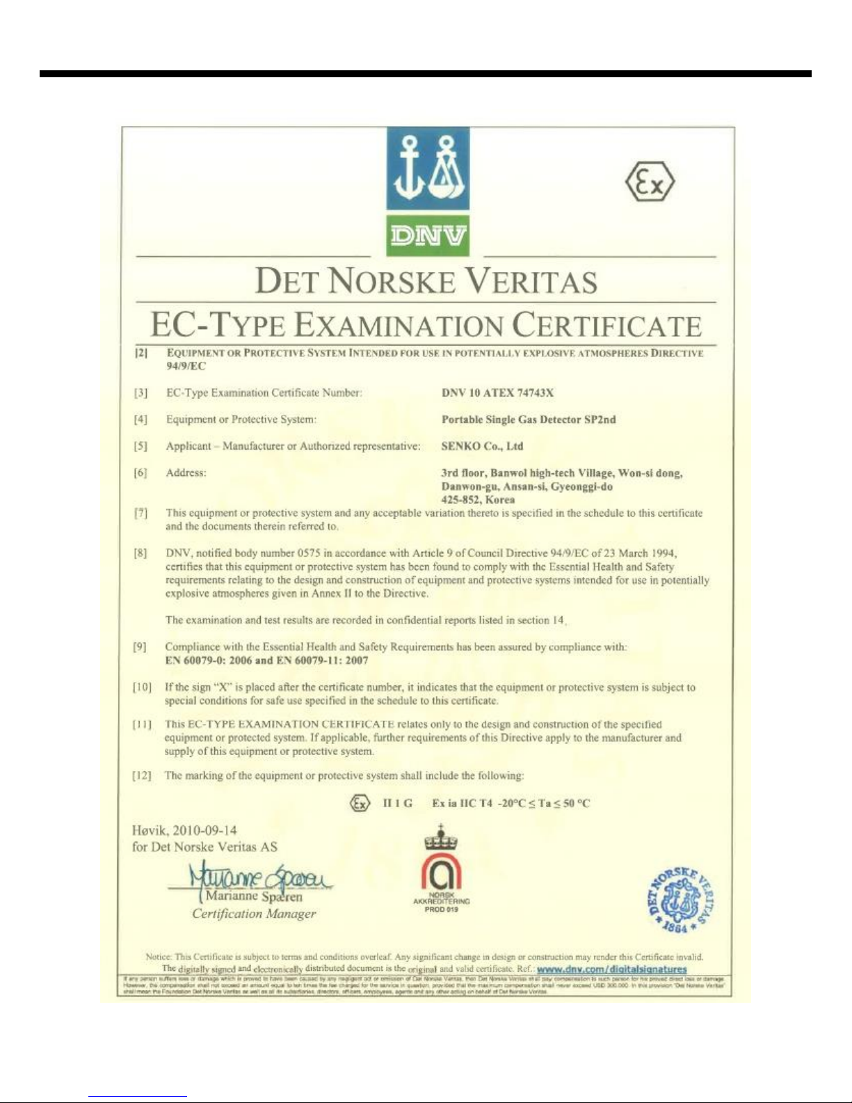
16
Certificates
Page 18
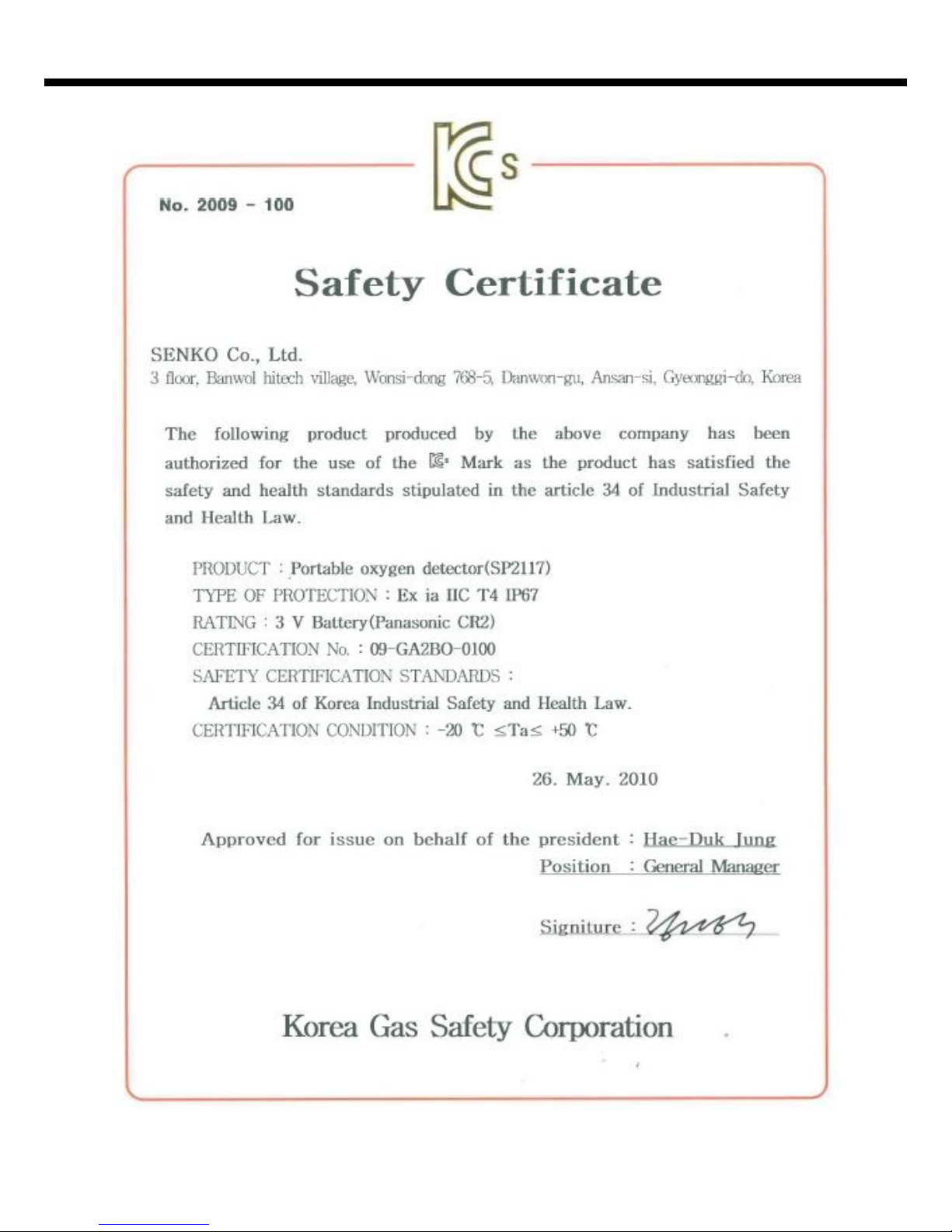
17
Certificates
Page 19
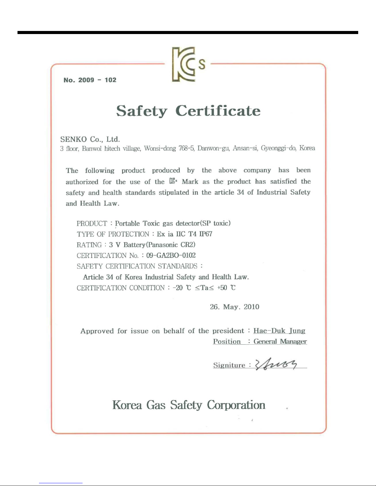
18
Certificates
 Loading...