

Page 1

Jameco Part number 151482
Ultrasonic Sensor
with RS-232 Output
User's Guide
Jameco Part Number 151482
Senix Corporation, 52 Mapl e S t., Bri s tol , VT 05443
© 1998 by Senix C orporati on
Page 2

Jameco Part number 151482
Product
Overview
The 151482 product is an ultrasonic sensor design ed t o
measure the distance between its transducer and a user
target. The distance is measured without contacting the
target object, and is accomplished by se n ding an
ultrasonic "pulse" and measuring the time for the pulse
"echo" to return from the target object. The measu red
time is related to the speed of sound of the pulse. After
the distance (time) is m easu red, th e sen s or tran smits the
distance as binary dat a on the RS-232 output. Each cou n t
of the binary dat a repres en ts a di s tan ce of .013536 i n ch es
at nominal speed of sound. The sensor provides data up
to a maximum range of 10 feet.
The 151482 consists of a circu it board, u l tras on i c
transducer, transducer connecting cable, 3.5" DOS
compatible floppy di skette, computer conn ecti n g cable
and this user manual.
performance, course of dealin g or u s ag e of trade; (C )
Any obligation, liability, right, claim or rem edy in tort,
whether or not arising from the negligence of Senix
(whether active, passive or imputed); and (D) Any
obligation, liability, right, claim or remedy for loss or
damage to any produ ct .
Exclusion of Consequential and Other Damages. Senix
shall have no obligation or liability, whether arising in
contract (including warranty), tort (including active,
passive or impu t ed n eg l igence) or otherwis e, f or l oss of
use, revenue or profit with respect to any non
conformance or defect in an y product delivered under
this agreement, or for an y other direct, incidental or
consequential damages.
Governing Law. The terms and conditions of this
agreement shall be govern ed by the domestic law of th e
State of Vermont, U.S.A.
Revision History
Initial product release April 1, 1998
Warranty
Senix, Inc. will repair or replace, at our option, any part
found by us to be defective in material or workmanship if
the product is received by Senix , f reig h t prepaid, within
one year from the date of original shipmen t to buyer.
Disclaimer and Release. The warranties, obligations and
liabilities of Senix and the remedies of buyer set forth
above are exclusive and in substitution for, and buyer
hereby waives , releases an d ren ou nces all oth er
warranties, obligations and liabilities of Senix and all
other rights, claim, and remedies of buyer ag ain st Sen i x ,
expressed or implie d, aris i n g by law or otherwise,
including but not limited to: (A) Any im plied w arranty or
merchantability or fitness; (B) Any im plied w arranty
arising from course of
Senix Corporation, 52 Mapl e S t., Bri s tol , VT 05443
Page 2
Page 3

Jameco Part number 151482
ABLE OF CONTENTS
T
PRODUCT OVERVIEW
Revision History
Warranty
...................................................................................................................................................
...............................................................................................................................................................
......................................................................................................
ULTRASONICS OVERVIEW
Introduction
Advantages
Typical Applications
GETTING STARTED
Unpacking
Specifications
Mounting
Beam Pattern
Orientation
Connections
OPERATION
Starting the sensor
Distance Calculation
Software
Performance
Precautions
Adjustments
...........................................................................................................................................................
............................................................................................................................................................
.............................................................................................................................................
...........................................................................................................
.............................................................................................................................................................
........................................................................................................................................................
...............................................................................................................................................................
.........................................................................................................................................................
............................................................................................................................................................
..........................................................................................................................................................
..........................................................................................................................
.................................................................................................................................................
.............................................................................................................................................
................................................................................................................................................................
..........................................................................................................................................................
............................................................................................................................................................
..........................................................................................................................................................
.............................................................................................
2
2
2
4
4
4
4
5
5
5
5
6
6
6
7
7
7
7
8
8
8
IN CASE OF DIFFICULTY
Basic Checkout
Common Problems
Repairs and Returns
.....................................................................................................................................................
...............................................................................................................................................
..............................................................................................................................................
Senix Corporation, 52 Mapl e S t., Bri s tol , VT 05443
.................................................................................................
Page 3
9
9
9
9
Page 4
Jameco Part number 151482
151482 - Ultrasonic Sensor User 's G uide
Ultrasonics
Overview
Introduction
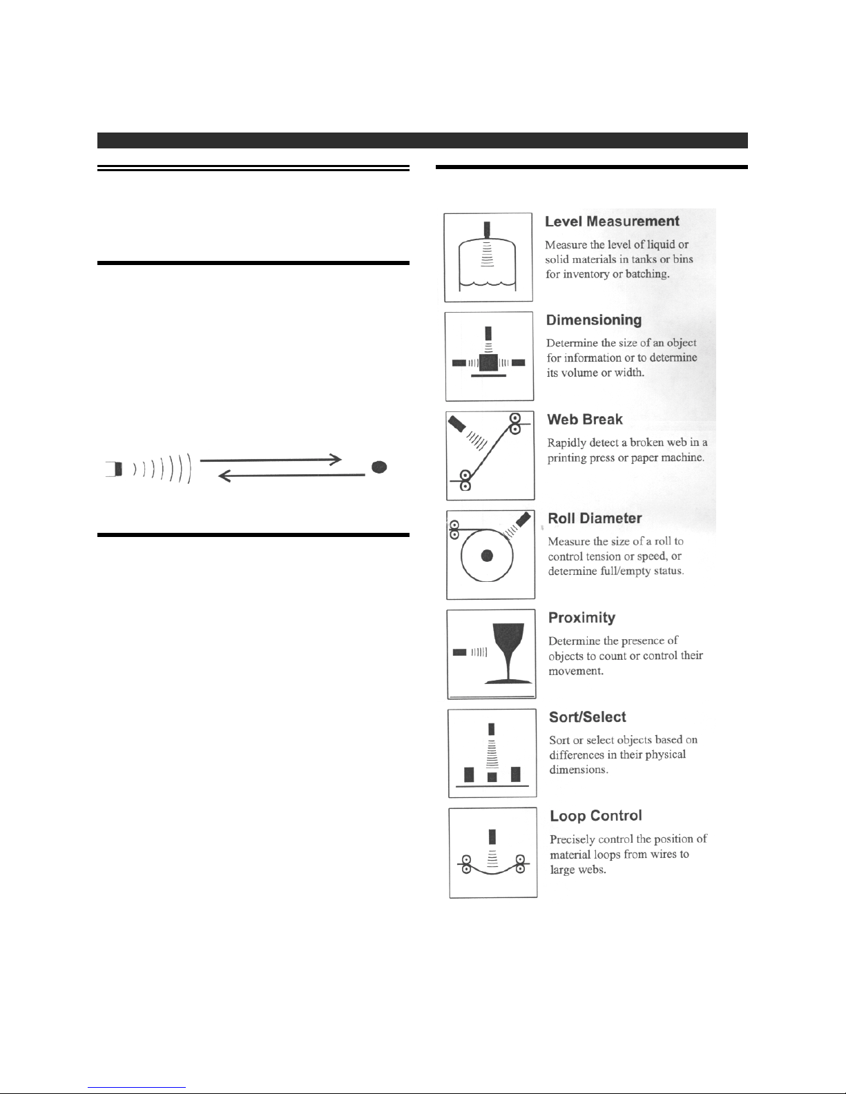
Ultrasonic sensors meas u re th e dist an ce or presen ce of a
target object by sensing a sound wave, above the range of
hearing, at the object and then meas u ring th e time for the
sound echo to return. Knowing the speed of sound, the
sensor can determine th e dist an ce of th e object from the
transducer element.
(1) Ultrasonic pulse transmitted from s en s or
Typical Applications
(2) Ultrasonic echo returns from target
Advantages
Non-contact
Measures through the air without touching the
target object, at relatively large distances.
Object Ranging
Object distance is measured rather than just th e
presence or proximity.
Distance Proportional Output
The sensor's out pu ts are proport ion al or rela te d to
the measured target range.
High Resolution
Precise discrimination of target position.
Unaffected by Target's Optical Characteristics
The sensor's operation is not sensitive to ambient
light levels, the target color, or target's optical
transparency or reflectivity.
Sensitive
Detects large and small objects.
Senix Corporation, 52 Mapl e S t., Bri s tol , VT 05443
and many more...
Page 4
Page 5
Jameco Part number 151482
Getting
Started
Unpacking
Check that you received the f ollowing items:
Circuit board
•
Ultrasonic transducer with con n ectin g cable
•
RS-232 Compu ter C abl e
•
3.5" DOS compatible floppy diskette
•
151482 - Ultrasonic Sensor User 's G uide
Transducer
Type Electrostatic Ultrasonic
Frequency 50 kHz
Beam Shape Conical
Beam Angle 15 degrees total @ 3db down
Temperature - 30 t o +70 C (- 20 t o +160 F)
Board Connection Blade terminals
Size 1.69" diam et er x 0.5" deep
Weight 0.3 oz.
Mounting
Ultrasonic transducer
The transducer mounts in a 1.54" diam eter circu l ar h ole
cut into any sheet material. The transducer can be glued
using a resilient compound such as GE Silicone Sealant.
This manual
•
Specifications
Circuit Board
Power Input 8-24 VDC @ 40 m a.
Range 6 inches to 10 feet
Output RS-232, Transmit on ly
Output Format 9600 baud, 8 data bits, 1 stop
bit, no parity
Output Protocol 3 character burst:
#1:55H (sync character)
#2: LSB count data
#3: MSB count data
Resolution 0.013536 inches/count at
room temperature
Temperature 0 to +70 C (32 to 160 F)
Humidity 5-95%, non-condensing
Measurement Period 50 mSec (20 Hz update)
Interface connections Terminal Block
Transducer connection 2-pin Molex
Weight 1.6 oz.
Size 2.85L x 1.85W x 1.25H
Grounding
If the sheet material is m etal, s u rf ace con tact to
the transducer will connect the surf ace to the
sensor's ground (PWR-). This is allowable as
long as it doesn't conflict with other wiring .
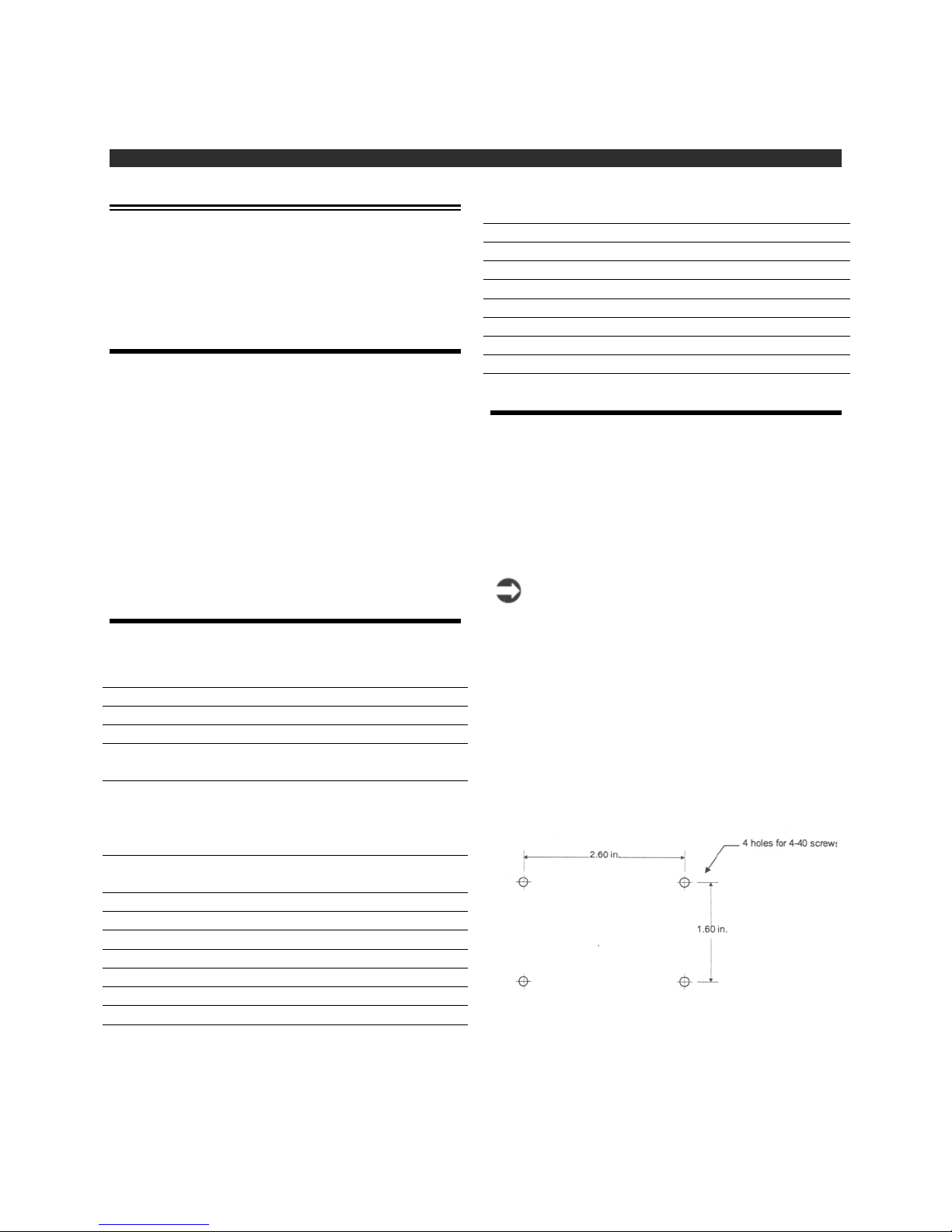
Circuit board
The circuit board moun ts on 4 s t an dof f s u s i n g 4-40
screws in the following h ole pattern:
Senix Corporation, 52 Mapl e S t., Bri s tol , VT 05443
Page 5
Page 6
Jameco Part number 151482
151482 - Ultrasonic Sensor User 's G uide
Beam Pattern
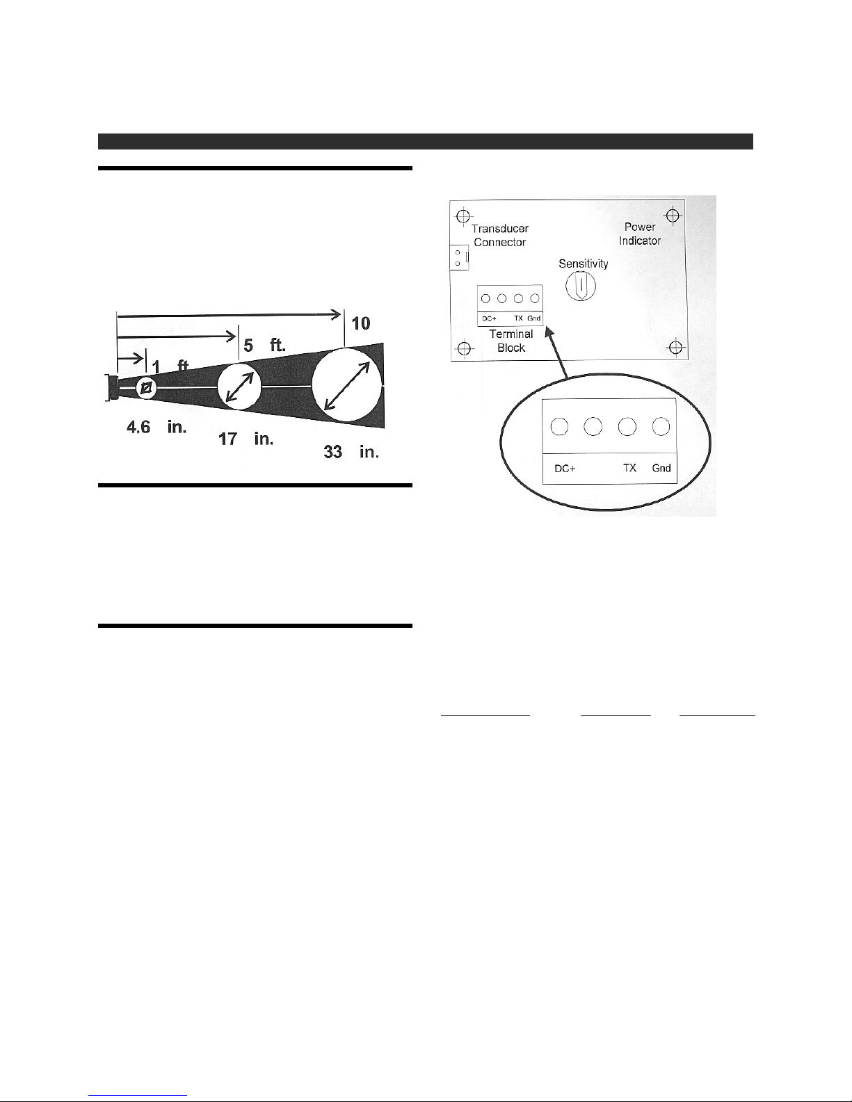
The beam pattern is conical w ith a total ang l e of abou t 15
degrees. The cone starts at the face of th e s en sor at abou t
1.5 inches in diameter and g rows from there as s h own in
the diagram below. The beam pattern is approximate and
represents the boundary where the return echoes are 3db
down.
Orientation
The transducer orientation should be perpendicular to the
target object for best results. The sensor will loose the
target if the ultrasound energ y is reflected away f rom the
transducer rather than back to it. Cu rv ed or sph erical
objects make good targ ets . Mak e s u re ot h er u n i n ten ded
targets are not visible to the sensor.
Indicator will light and the tran sducer will begin clicking
repetitively.
RS-232 Data Output
Connections
Ultrasonic transducer
The ultrasonic transducer is provided with a cable
attached. Connect the transducer cable (2-pin brown
female Molex connector) into the mating Transducer
Connector on the circuit board.
The two BLADE terminals press onto mating termin als
on the transducer. The shield end (g rou n d) s h ou ld be
attached to the terminal of the transducer's outer shell,
placing the outer shell at ground potential.
Power Input
Connect a +8 to 24 volts DC power s u pply via the DC +
GND
and
power backward will not dam ag e the board. As soon as
you apply power, the Power
terminals of the Terminal block Connecting the
Senix Corporation, 52 Mapl e S t., Bri s tol , VT 05443
The system prov i des an R S - 232 s eri al dat a ou t put on the
TX terminal of the terminal block as s h own in the above
drawing. There is no serial data input. The output is
connected as follow s to an R S - 232 dev ice i n pu t :
Sensor Terminal
TX RS-232 In RED
Gnd Ground GREEN
The RS-232 cable included with the sensor con n ect s t h e
sensor to a standard personal computer serial port
(COM1 or COM2). One end of th e cabl e i s a 9- pin
female (DB9F) connector that mates with a standard PC
9-pin COM port connect or. The oth er cabl e en d h a s 2
tinned wires that connect to the sensor terminal block
listed above in the Sensor Terminal column.
Page 6
Input Device RS-232 Cable
Page 7
Jameco Part number 151482
Operation
Starting the sensor
Following installation an d con nection accordin g to th e
preceding sections, the sensor starts running as soon as
the DC power is applied.
When the sensor is running the Power Indicator should
be ON and a repetitive clicking heard from the
transducer.
Distance Calculation
The sensor's measu red dis tan ce is represen ted by the data
transmitted on the TX terminal of the term inal block. The
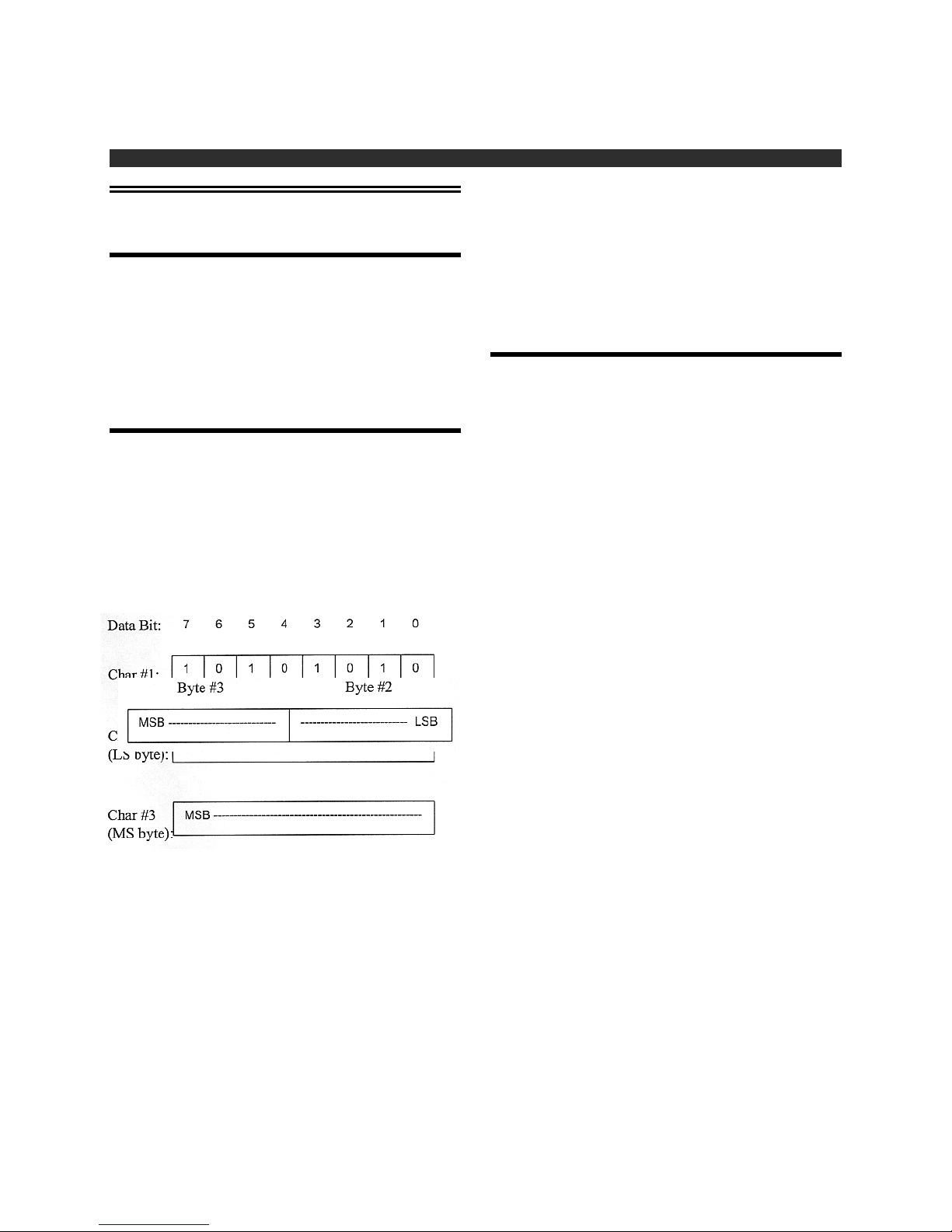
data is contained in 3-characters burst with the followin g
definition:
#1:55H (sync character)
#2:LSByte of cou n t dat a
#3:MSByte of count data
Bytes 2 and 3 combined are combined into a single
16-bit word represent in g a di s tan ce proport ion al v alue as
shown below:
151482 - Ultrasonic Sensor User 's G uide
The distance can be calculated from th e 16- bit data v alu e
as follows:
Inches = Value * 0.013536
The maximu m count value is abou t 8865, represen t ing a
distance of 10 feet (120 in ch es). Target s clos er th an 6
inches will generally return valu es dow n to about 5.2
inches. If the sensor does not detect a target within 10
feet, the sensor transm its a zero valu e.
Software
A QuickBasic example program is prov i ded on th e
included floppy disk th at will read the sensor data output
and display the meas u red dist an ce on a person al
computer screen. The following files are provided on th e
diskette:
JAMECO1.EXE
JAMECO1.BAS
JAMECO1.EXE showing how t h e prog ramming an d
display of sensor data are accomplished.
Run the program as follows:
1. Insert the floppy di s k in t o th e computer. The
program can be run from floppy, or t h e 2 f i le s li st ed
above can be copied to a subdirectory on the
computer's hard driv e an d ru n f rom there.
2. Connect and power t h e s en s or as descri bed
previously in Getting Started.
3. Run the program by typin g JA MEC O 1 at t h e DO S
prompt. This runs t h e ex ecu ta ble f i le . The program
can also be run as a DOS task un der Windows 3.1
or Windows 95.
4. The program will first display "Which COM port is
the sensor connected to (1/2)?" Type the number 1
or 2 depending upon which port you are using, then
press the <Enter> key.
5. The program now di spl ays distance. A zero v alu e i s
displayed if no target is detected within 10 feet. The
data is updated every 50 mSec. To exit the
program, hit any key.
-- DOS executable program
-- QuickBasic source code for
Senix Corporation, 52 Mapl e S t., Bri s tol , VT 05443
Refer to the source code file JAMECO1.BAS to
understand how to read s en s or data an d calcu late the
distance.
Page 7
Page 8

Jameco Part number 151482
151482 - Ultrasonic Sensor User 's G uide
Performance
Update Rate
The sensor measures distance repetitively at an interval
of approximately 50 milliseconds. This is the interval
between the "clicks" heard from th e tran sdu cer. A f ter
each measuremen t, th e 3 ch aracters of data are
transmitted on the RS - 232 ou tpu t.
Target Considerations
The target must reflect the u ltrasou n d en ergy back to the
sensor. Sensor performance will be affected by th e
strength of the "echo". Flat surf aces are bes t when
perpendicular to the beam direction. Cu rv ed s u rf aces are
generally good targets becau s e a portion of th e en erg y is
generally reflected directly back to th e sen s or.
Low-density materials including some foams, cloth and
powders may exhibit reduced detection ran g e, or can
absorb or be transparent to ultrasound. In many cases
these materials are easily detected, s o testing a material
sample is recomm en ded. Increas in g th e s ens or's gain
using the sensitivity adjustm en t may be required.
Adjustments
Sensitivity
This adjusts the electronic sensitivity to the strength of
the ultrasonic echo being return ed from the target object.
Very small or sound absorbing targets may not send a
very strong ech o an d th eref ore may require increased
sensitivity for stable detection. The sensitivity
potentiometer is located next to the terminal block on the
solder side of the circuit board. The unit is shipped at
mid range and in general it does not require adjustment.
Sensitivity can be increased by rotating the potentiom eter
clockwise and decreased by counterclockwise rotation .
Full rotation of t h e pot is 180 deg rees .
Ultrasonic Tuning Adjustments
The ultrasonic tuning adjustments consist of a
transformer T1 (silver case) and in du ctor L 1. These
generally do not require adjustment unless the cable
length to the transducer is lengthened.
To adjust these components:
Temperature Effects
The most significant f actor th at af f ects measurement
accuracy is temperature. A t room temperature, a change
of 10 degrees will result in approximately 1% change in
the speed of sound and therefore th e same change in the
distance output. This model sensor does not compensate
for temperature affects.
Precautions
•
•
Keep unintended targets f rom transducer's field
of view. Keep the beam pattern in mind.
Keep transducer away from ultrasonic noise
sources, such as pressurized air n ozzles
Senix Corporation, 52 Mapl e S t., Bri s tol , VT 05443
1. Put an oscilloscope probe on test point TP1 and
set the scope to trigger on the transmitted pulse.
This test point is a hole in the PCB that is
labeled on the compon en t s ide of the board.
2. Using delayed sweep, monitor a target echo
signal and adjust T1 for maximum amplitude.
3. Using the same s ig n al as in st ep 2, adjust L 1 for
maximum amplitude.
Transducer Cable Length
As the cable length is increased, sensitivity will
decrease. A practical cable maxim u m length is
20 feet, and longer cables should be shielded in
electrically noisy areas.
Page 8
Page 9

Jameco Part number 151482
In Case of
Difficulty
Basic Checkout
With DC power appli ed t o th e s e n s or th e Power Indicator
should be ON and a click in g sound should be h eard f rom
the ultrasonic transducer.
If the Power Indicator is not ON check th e power
connections. The board will not be damaged by a reverse
polarity connection.
If the Power Indicator is ON but the sensor is not
clicking, check the cable connection s between the circuit
board and ultrasonic tran s du cer. L ook f or brok en or
shorted wires or l oos e con n ect ors.
151482 - Ultrasonic Sensor User 's G uide
Common Problems
Output stuck at short distance value
1. An object is near the front of th e sen s or th at is
being detected, possibly associated with the
mounting arrangement.
2. The sensor is "self-detecting" its own transmit
signal. Reduce the sensitivity by tu rnin g th e
Sensitivity adjustment counterclockwise.
3. No target is being detected. Place a target in
front of the transducer at a kn own distance and
test for a reasonable voltage value.
Repairs and Returns
If you need to discus s a problem or return a unit please
call the followi n g n u mber for technical support :
Jameco Electronics
(415)592-8097 (voice)
(415)592-2503
Senix Corporation, 52 Mapl e S t., Bri s tol , VT 05443
Page 9
 Loading...