

Page 1
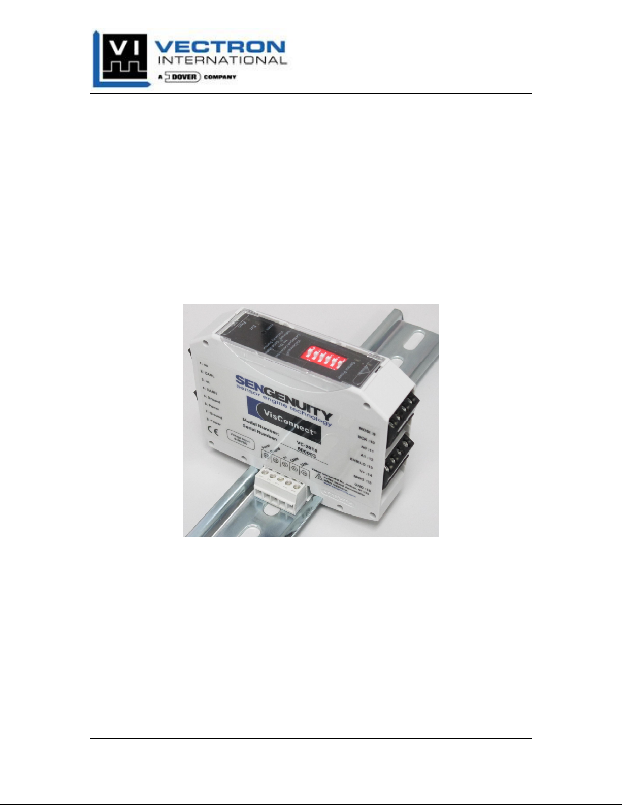
VC-2xxx Series Converter
Product Manual
VisConnect® VC-2xxx Series Converter
Product Manual
Products Covered in this manual:
VC-2010 CANopen Converter
Vectron International, Inc. Doc #: HDOC200006, Rev A / April 2012
267 Lowell Road, Hudson, NH USA Pg. i
Page 2

VC-2xxx Series Converter
Product Manual
Revision Table
Revision Date Change
A April 2012 Initial Release
Vectron International, Inc. Doc #: HDOC200006, Rev A / April 2012
267 Lowell Road, Hudson, NH USA Pg. ii
Page 3

VC-2xxx Series Converter
Product Manual
Table of Contents
Overview............................................................................................................................. 1
Technical Data .................................................................................................................... 2
Converter Installation.......................................................................................................... 3
Field Installation ............................................................................................................. 3
Converter Installation on DIN Rail................................................................................. 3
Converter Removal from DIN Rail................................................................................. 4
Grounding ....................................................................................................................... 5
Connector Assignment........................................................................................................ 7
VC-2010 CANopen Converter Connector Assignments ................................................ 7
VC-2010 CANopen Converter Signal Descriptions ....................................................... 9
VC-2010 CANopen Converter ......................................................................................... 10
CANopen Conformance................................................................................................ 10
Firmware State Machine ............................................................................................... 10
DIP Switch Settings ...................................................................................................... 10
CANopen Layer Setting Services ................................................................................. 12
CANopen Diagnostic LEDs.......................................................................................... 13
CANopen Object Dictionary & Supported Functions .................................................. 14
1000h Device Type ................................................................................................... 14
1001h Error Register................................................................................................. 15
1017h Producer Heartbeat Time ............................................................................... 15
1018h Identity Object ............................................................................................... 15
1200h Server SDO Parameter................................................................................... 17
1800h, 01, 02 Transmit PDO Parameters ................................................................. 17
1A00h, 01, 02 Transmit PDO Mapping.................................................................... 18
6000h Temperature Reading..................................................................................... 19
6001h Viscosity Reading .......................................................................................... 20
6002h Sensor Status.................................................................................................. 20
VC-2010 CANopen Converter Troubleshooting Guide ................................................... 23
Table of Figures
Figure 1: Converter Block Diagram .................................................................................. 1
Figure 2: Converter Installation on DIN Rail .................................................................... 3
Figure 3: Optional TBUS Connectors................................................................................ 4
Figure 4: TBUS Connectors on a DIN Rail ....................................................................... 4
Figure 5: Converter Removal from DIN Rail .................................................................... 5
Figure 6: VC-2xxx Grounding Diagram............................................................................ 6
Figure 7: TBUS Connector Pin Numbers .......................................................................... 8
Figure 8: Firmware Block Diagram................................................................................. 10
Figure 9: DIP Switch Configuration ................................................................................ 11
Figure 10: VC-2010 CANopen Converter Top Panel...................................................... 13
Vectron International, Inc. Doc #: HDOC200006, Rev A / April 2012
267 Lowell Road, Hudson, NH USA Pg. iii
Page 4

VC-2xxx Series Converter
Product Manual
Table of Tables
Table 1: Electrical and Mechanical Technical Data .......................................................... 2
Table 2: VC-2010 Screw Terminal Assignments .............................................................. 7
Table 3: VC-2010 TBUS Connector Assignment ............................................................. 7
Table 4: Converter & Sensor Cable Wiring Assigment..................................................... 8
Table 5: CANopen Converter DIP Switch Node IDs ...................................................... 12
Table 6: CANopen Converter DIP Switch Bit Rate ........................................................ 12
Table 7: CANopen Converter SIP Switch Bus Termination ........................................... 12
Table 8: VC-2010 CANopen Converter LEDs ................................................................ 14
Table 9: Sensor Status Word............................................................................................ 21
Manual Acronyms and Notations
0h: ‘h’ is the letter used to identify a number in hexadecimal format.
0d: ‘d’ is the letter used to identify a number in decimal format.
LED: Light emitting diode
OEM: Original Equipment Manufacturer
SPI: Serial Peripheral Interface
VC: The VisConnect® Product identifier.
VS: The ViSmart® Sensor identifier.
Note CANopen protocol specific acronyms will generally not be defined in this
manual. The reader is encouraged to review DS301. Additional
information is available at CANopen in Automation,
http://www.can-cia.org.
VisConnect, ViSmart, and SenGenuity are Registered Trademarks of Vectron
International Inc.
Vectron International, Inc. Doc #: HDOC200006, Rev A / April 2012
267 Lowell Road, Hudson, NH USA Pg. iv
Page 5
VC-2xxx Series Converter
Product Manual
OVERVIEW
The VisConnect® VC-2xxx Series Converters are electronic devices which interrogate the
VS-25xx ViSmart® Series Solid-State Viscosity Sensors to provide measurements of
viscosity and temperature. The viscosity and temperature outputs are provided at
intervals of once per second.
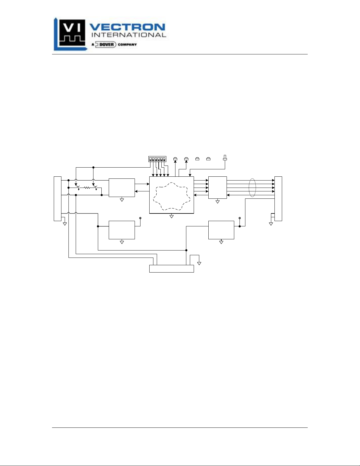
Below is a high level block diagram of the VC-2010 CANopen Converter electronic
assembly located within the housing.
LED
Reset
(+7Vdc)
120 ohm Termination Enable
Run LED
Power LED
Sensor Power
(+5Vdc)
Err LED
+7Vdc
SPI bus
Screw Terminals
To/From
V+
GND
sensor
CANH
CAN
CANL
Screw Terminals
Power
Transceiver
+5Vdc
5V DC–DC
Converter
Microprocessor
5V I/O
Buffers
Firmware
7V DC–DC
Converter
TBUS Connector
Figure 1: Converter Block Diagram
The VC-2xxx Series Converters are DIN rail mountable and have easily accessible screw
terminal connections for process interface connections and Sensor connections. The
Converters can also be connected to a optional DIN rail TBUS connector which
minimizes system wiring and decreases installation time.
The DIP switches available on the top of the Converter, minimize system setup by
allowing fast bus configuration. Settings for bus bit rate, node ID, and bus termination
are available.
Status LEDs easily help identify Converter and Sensor Status.
The Converters are powered using a DC power supply.
Vectron International, Inc. April 2012
267 Lowell Road, Hudson, NH USA Pg. 1
Page 6
VC-2xxx Series Converter
Product Manual
TECHNICAL DATA
The following table displays some of the technical data for the VC-2xxx Series
Converter. The VisConnect Converter Datasheet, available at www.SenGenuity.com,
will have additional information.
Table 1: Electrical and Mechanical Technical Data
Power Supply 9VDC to 36VDC, < 100mA w/ Sensor connected
Operating/Storage
Temperature
Dimensions 70.4mm (height) x 85mm (depth) x 22.5mm (width)
Mounting 35 mm DIN rail
Connector Type -
Screw Terminals:
TBUS Plugs
Vibration EN 60068-2-6 & EN 60068-2-64
Shock EN 60068-2-27
Protection Degree IP 20
0 to 60ºC / -40 to 85ºC
Pitch: 5.0 mm pitch:
Wire sizes: 0.14 mm2 to 2.5 mm2
26 awg to 14 awg
Tightening torque: 0.5 Nm (min) to 0.6 Nm (max)
Stripping length: 8 mm
Pitch: 3.81 mm pitch:
Wire sizes: 0.14 mm2 to 1.5 mm2
26 awg to 15 awg)
Tightening torque: 0.22 Nm (min) to 0.25 Nm (max)
Stripping length: 7 mm
Phoenix Contact P/Ns: 1719697 & 1719707
Vectron International, Inc. April 2012
267 Lowell Road, Hudson, NH USA Pg. 2
Page 7
VC-2xxx Series Converter
Product Manual
CONVERTER INSTALLATION
F
IELD INSTALLATION
VC-2xxx Series Converters are not approved for use in Hazardous Area classified
locations. It is strongly recommended that the VC-2xxx Converters be installed in an
enclosure NEMA type I, or equivalent.
Follow Table 1 for the recommended use of wires and strip lengths for the screw
terminals and TBUS plugs.
C
ONVERTER INSTALLATION ON
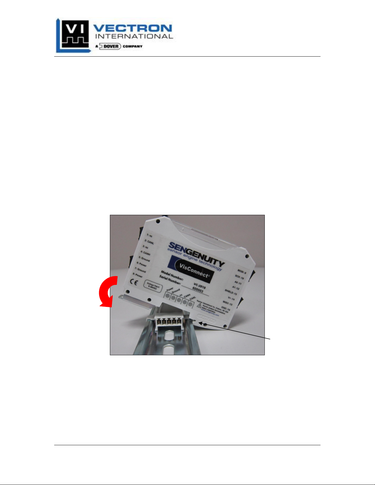
The VC-2xxx Series Converters are intended to be installed on a standard 35 mm DIN
rail. When mounting to a DIN rail, engage the Converter DIN rail guides first then pivot
the Converter onto the DIN rail. The spring loaded clasp will latch around onto the DIN
resulting in a firmly seated product.
DIN R
AIL
Converter DIN
Rail guides
Figure 2: Converter Installation on DIN Rail
When using the optional TBUS DIN rail connector, snap the TBUS connector first into
the rail, then mount Converter to the rail in the same method specified above. The TBUS
connector and Converter can be mated in one way only. Do not force the Converter onto
the TBUS connector otherwise product damage may result!
Vectron International, Inc. April 2012
267 Lowell Road, Hudson, NH USA Pg. 3
Page 8
VC-2xxx Series Converter
Product Manual
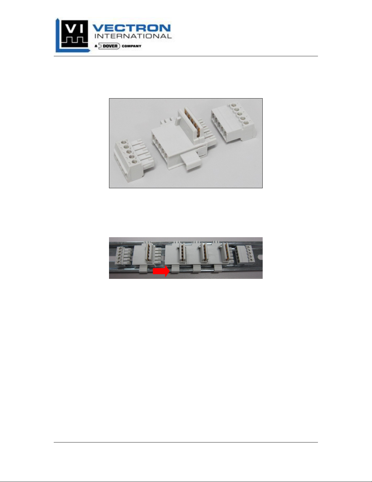
Figure 3 shows the optional TBUS connector with male and female plugs available with
the Converters. The Converters may be ordered with just the center TBUS connector or
with all three shown in the figure.
1
2
3
4
5
Figure 3: Optional TBUS Connectors
The TBUS connector allows side-by-side installations of the Converters. Figure 4 shows
multiple TBUS connectors installed on a DIN rail. First, install the TBUS connector onto
the DIN rail, then slide into adjacent TBUS connector.
Figure 4: TBUS Connectors on a DIN Rail
C
ONVERTER REMOVAL FROM
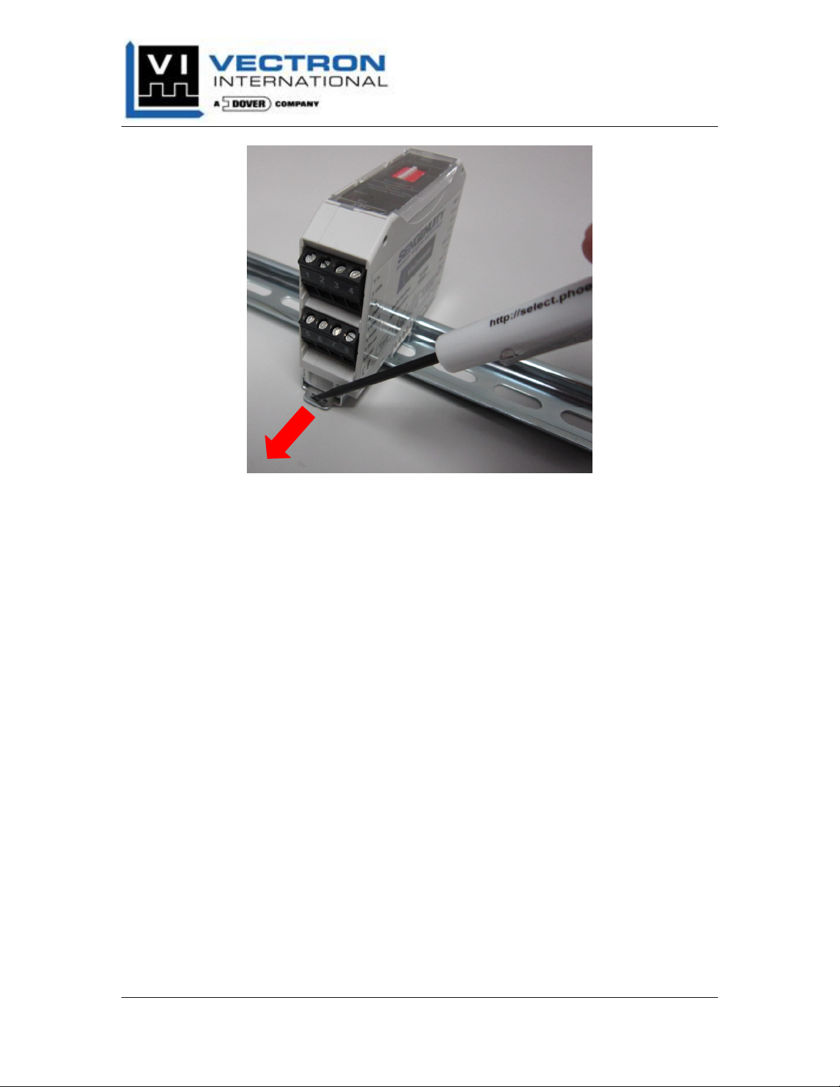
To remove the Converter from the DIN Rail, use a flat blade tool to pry the spring loaded
clasp away from the DIN rail in the manner shown in Figure 5. Next pivot the Converter
up away from the DIN rail and remove.
DIN R
AIL
Vectron International, Inc. April 2012
267 Lowell Road, Hudson, NH USA Pg. 4
Page 9
VC-2xxx Series Converter
Product Manual
Figure 5: Converter Removal from DIN Rail
G
ROUNDING
The Converter signals named Ground and GND are internally (electrically) connected.
Further, the Converter contains a metal clip on the DIN rail side of the package which is
also electrically connected to the Ground and GND signals. As such, when the Converter
is mounted on the DIN rail, the DIN rail is electrically connected to the ground on the
Converter. Care should be taken during installation to minimize and/or eliminate ground
loops between the Converter grounds and Earth ground.
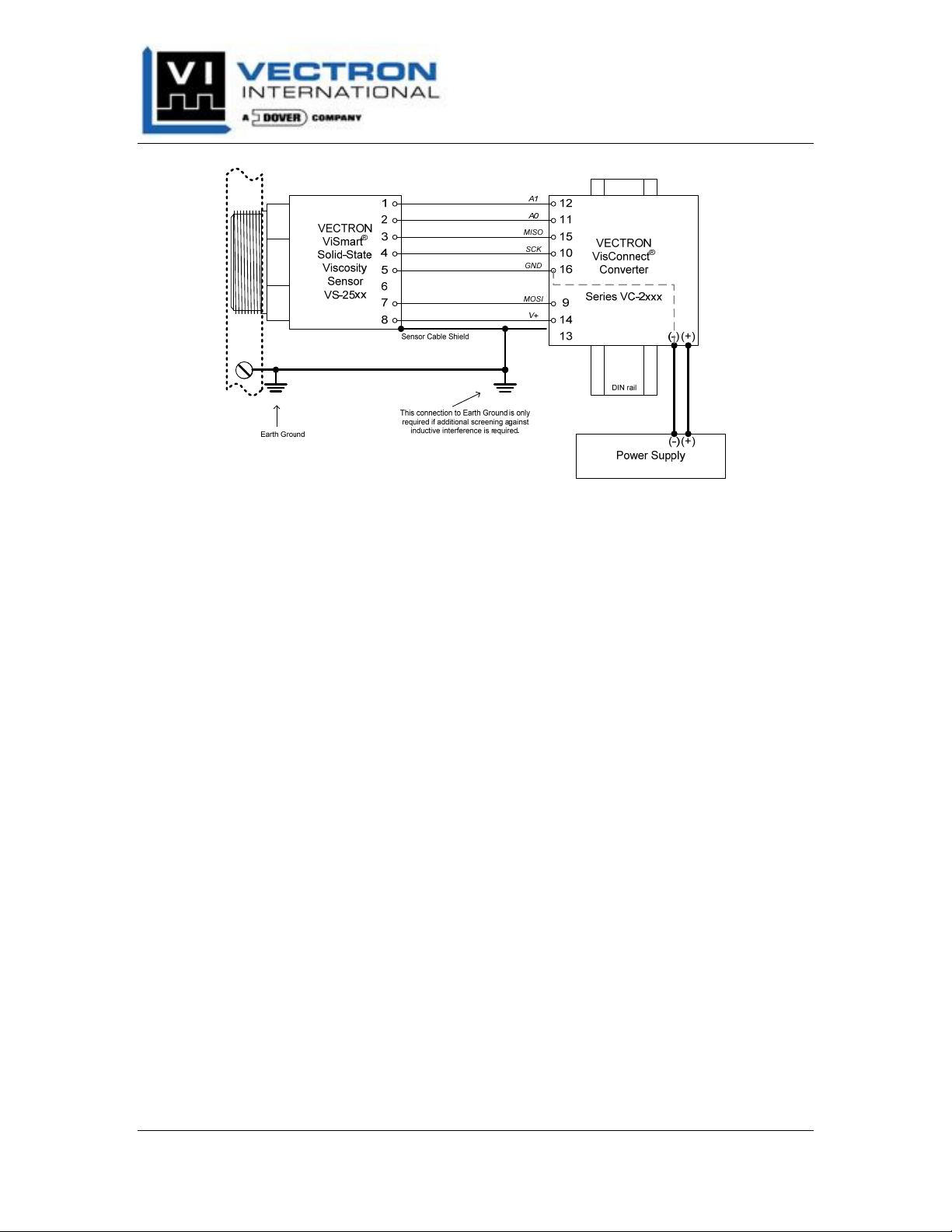
In order to minimize ground loops, it is recommended that the sensor cable shield be
connected at one location only, as shown in Figure 6 below.
Vectron International, Inc. April 2012
267 Lowell Road, Hudson, NH USA Pg. 5
Page 10
VC-2xxx Series Converter
Product Manual
Figure 6: VC-2xxx Grounding Diagram
In noisy electromagnetic installations, where for example highly inductive loads are
switching, it may be necessary to ground the sensor cable shield at one or more locations
along the cable length.
Vectron International, Inc. April 2012
267 Lowell Road, Hudson, NH USA Pg. 6
Page 11
VC-2xxx Series Converter
Product Manual
CONNECTOR ASSIGNMENT
This section identifies the screw terminal assignments and TBUS connectors for the VC2xxx Series Converters.
VC-2010 CAN
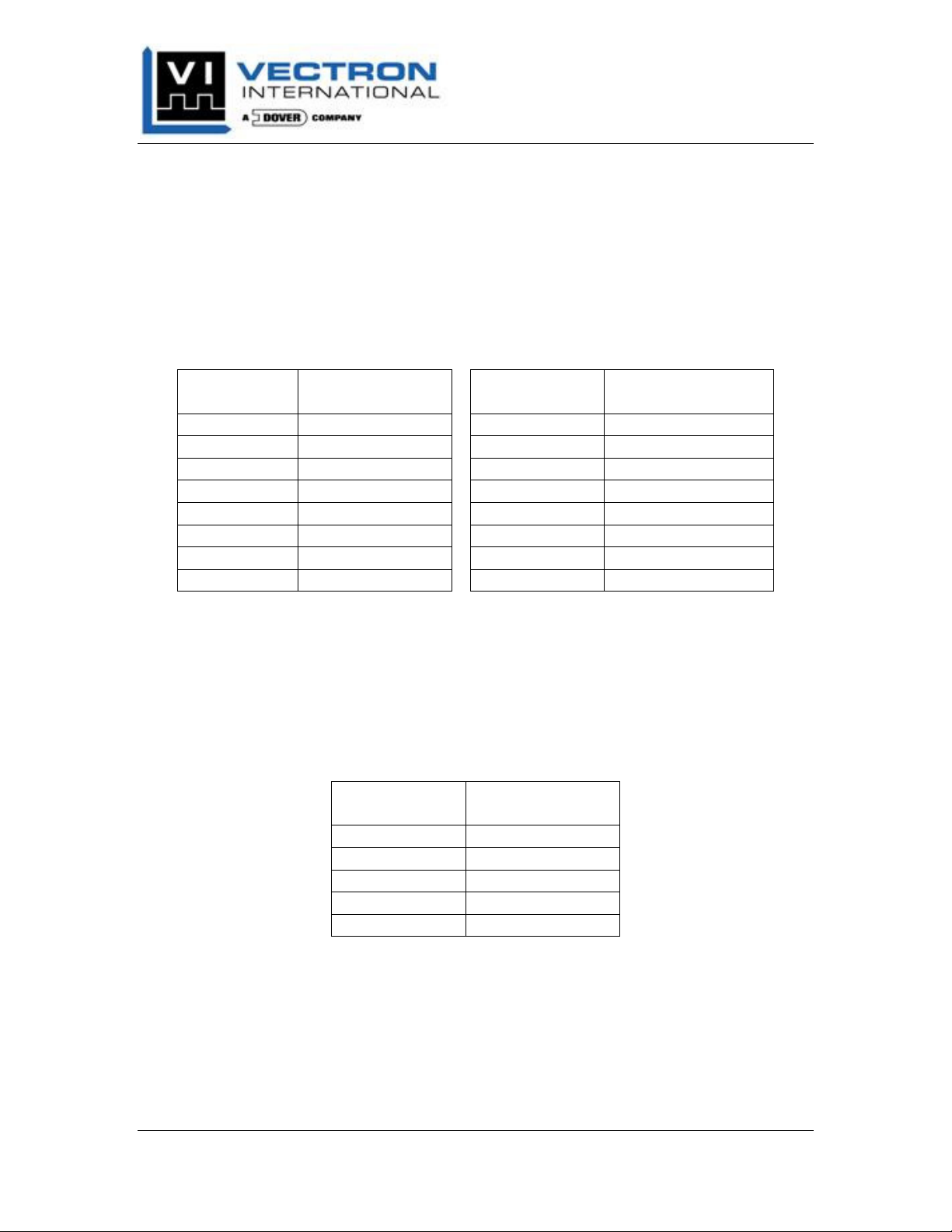
For the VC-2010, the following table summarizes the screw terminal pin assignments.
Table 2: VC-2010 Screw Terminal Assignments
Terminal
Number
1 nc 9 MOSI
2 CANL 10 SCK
3 nc 11 A0
4 CANH 12 A1
5 Ground 13 SHIELD
6 Power 14 V+
7 Ground 15 MISO
8 Power 16 GND
For the VC-2010, the Table 3 summarizes the TBUS connector assignments. Use Figure
7 as well to help cross reference the TBUS connector pin number with Signal Name.
The Sensor terminals 9-16, should be connected only when the Converter power is off. It
is permissible to wire the Sensor to the Converter before the Converter is mounted to the
DIN rail.
Table 3: VC-2010 TBUS Connector Assignment
OPEN CONVERTER CONNECTOR ASSIGNMENTS
Signal
Name
TBUS
Number
1 Power
2 Ground
3 nc
4 CANH
5 CANL
Terminal
Number
Signal
Name
Signal
Name
Vectron International, Inc. April 2012
267 Lowell Road, Hudson, NH USA Pg. 7
Page 12
VC-2xxx Series Converter
Product Manual
1 2 3 4 5
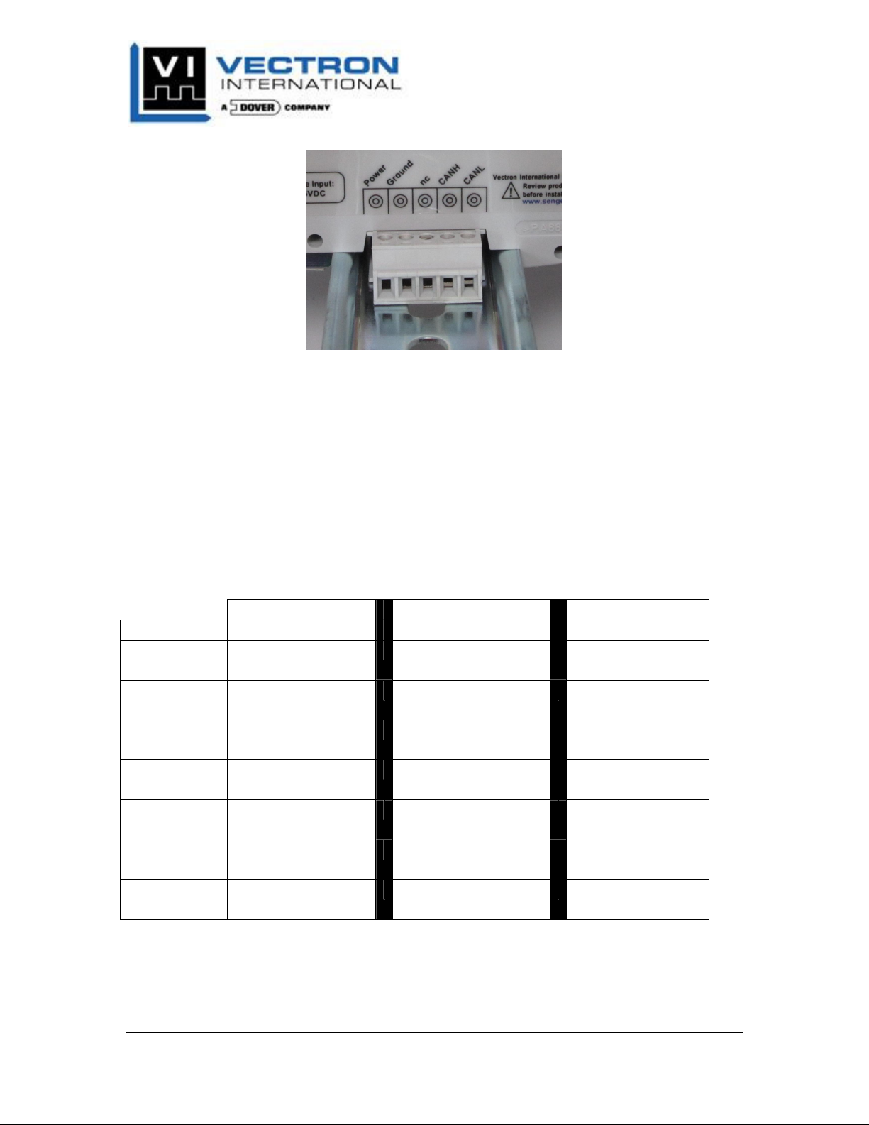
Figure 7: TBUS Connector Pin Numbers
The TBUS connector allows the Converter to be “hot swappable”. This allows minimal
interruptions to the other devices on the DIN rail. The Converters may be installed and
removed while DC power is applied to the TBUS connecter.
Converter, Sensor Cable, and Sensor Wire Color Assignment
Table 4 below shows the wire color assignments when using the recommended Vectron
sensor cable. The arrows indicate the direction in which the electrical signals are actively
driven.
Table 4: Converter & Sensor Cable Wiring Assigment
VC-2010
Signal Name Terminal Number
MOSI
SCK
A0
A1
V+
MISO
GND
The recommended Vectron Sensor cable has eight conductors. The eighth conductor, a
pink wire, is a ‘no connect’ inside then sensor and should be grounded at terminal 16.
9
10
11
12
14
15
16
Sensor Cable Color
→
(blue)
→
(yellow)
→
(brown)
→
(white)
→
(red)
←
(green)
←
(gray)
VS-25xx
M12 Pin Number
7
4
2
1
8
3
5
Vectron International, Inc. April 2012
267 Lowell Road, Hudson, NH USA Pg. 8
Page 13

VC-2xxx Series Converter
Product Manual
VC-2010 CAN
P
ROCESS SIGNALS/CONNECTIONS
Power The Power screw terminals and TBUS connection are electrically shorted
Ground The Ground screw terminals and TBUS connection are electrically shorted
CANH/CANL These signals should connect to the CAN_H and CAN_L signals on the
nc These screw terminals and TBUS connection should not be connected.
S
ENSOR SIGNALS/CONNECTIONS
A1, A0 These signals encode the chip selects within a VS-25xx Series Viscosity
SCK, MOSO These signals carry the clock and data outputs used for the SPI bus
MISO This signal carries the encoded SPI bus data from the VS-25xx Series
V+ This signal carries the DC power to the VS-25xx Series Viscosity Sensor.
GND This is the signal ground reference for the SPI signals and V+.
SHIELD This terminal connection can be used to ground the shield on the sensor
OPEN CONVERTER SIGNAL DESCRIPTIONS
together. This connection should be used to wire the DC power to the
Converter. Table 1 provides the DC supply voltage range.
together. This connection should be used to wire the DC power supply
return (ground) to the Converter.
CAN bus. This Converter supports CANopen protocol only.
Sensor. They are actively driven from a VC-2xxx Series Converter.
communication between a VS-25xx Series Viscosity Sensor and VC-2xxx
Series Converter. These signals are actively driven from a VC-2xxx
Series Converter.
Viscosity Sensor to the VC-2xxx Series Converter. The signal is actively
driven from the VS-25xx Series Viscosity Sensor.
It is sourced from a DC-to-DC regulator within a VC-2xxx Series
Converter and is typically around +7V.
cable. In most installations, it is not necessary.
Vectron International, Inc. April 2012
267 Lowell Road, Hudson, NH USA Pg. 9
Page 14
VC-2xxx Series Converter
Product Manual
VC-2010 CANOPEN CONVERTER
The VC-2010 CANopen Converter transmits viscosity and temperature data on the CAN
bus signals at intervals of once per second. The Converter’s CAN Node ID, bit rate, and
bus termination are easily set from the DIP switches on the top side of the package,
ensuring a fast system setup time.
CAN
OPEN CONFORMANCE
The Converter supports the CANopen application layer and communication profile as
defined in EN 50325-4. At the time of release of this manual, theVC-2010 CANopen
Converter is not yet a CiA1 compliant device. Vectron International is actively pursuing
compliance to EN 50325-4 and expects to be fully compliant in Q2 2012. The Vectron
International assigned CANopen Vendor ID is 0324h.
F
IRMWARE STATE MACHINE
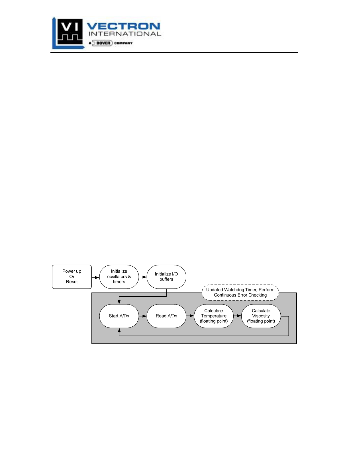
Figure 8 below shows a simplified block diagram for the Converter firmware. After
power up, the Converter initializes the microcontroller oscillators, timers, and I/O
buffers, then immediately starts and reads conversions on the ViSmart Sensor’s analogto-digital converters (A/Ds). The Converter then calculates the floating point temperature
and viscosity values. Not shown in the diagram, however, is that after the floating point
calculation the Converter transmits the temperature and viscosity values as TxPDOs.
The entire state machine repeats once per second while continuously updating the
microcontrollers Watchdog Timer and internal error status registers.
Figure 8: Firmware Block Diagram
DIP S
The DIP switches are provided to manually configure the CANopen node-ID, bit rate,
and bus termination. Switches 1 through 4 set the node-ID sequentially starting at 10 and
1
CiA: CANopen in Automation, http://www.can-cia.org.
Vectron International, Inc. April 2012
267 Lowell Road, Hudson, NH USA Pg. 10
WITCH SETTINGS
Page 15
VC-2xxx Series Converter
Product Manual
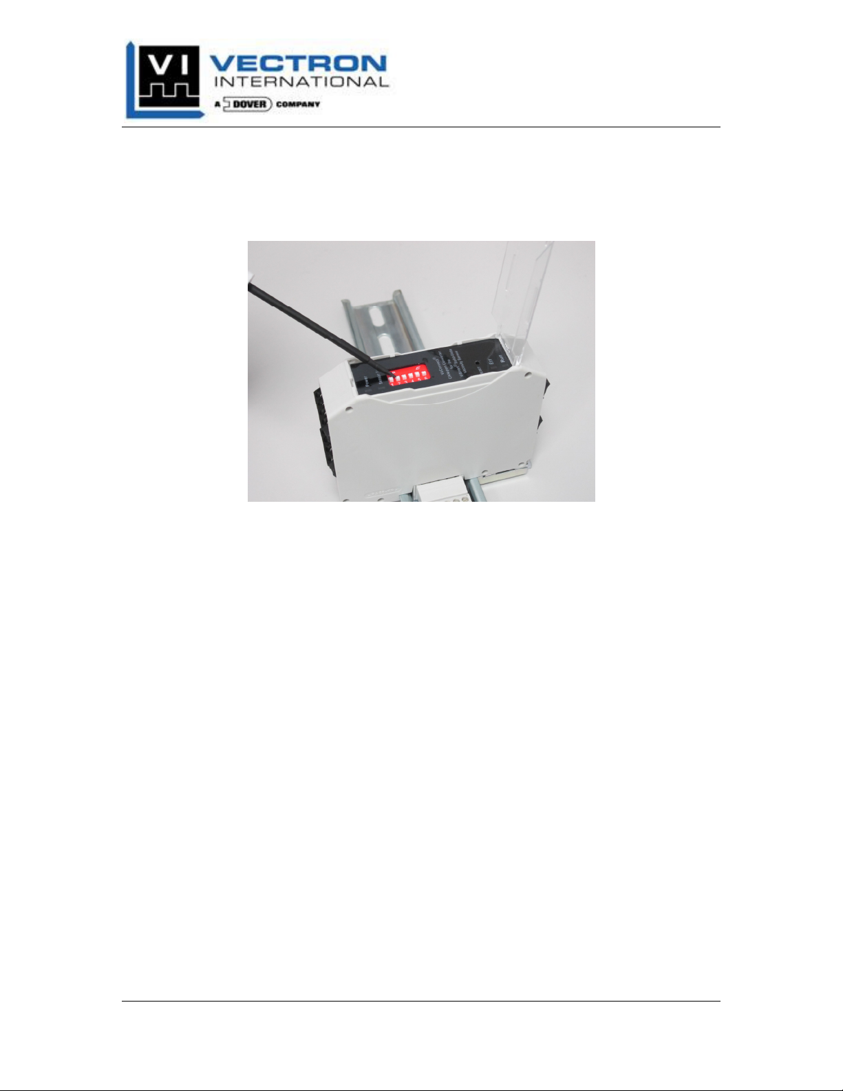
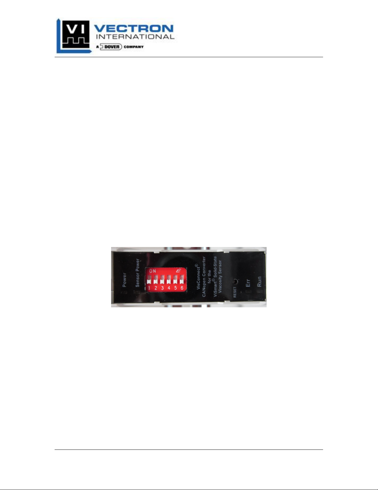
ending at 25. Switch 5 sets the bit rate at either 125 kbps or 250 kbps. Switch 6 sets the
120 ohm bus termination resistor. The DIP switches are accessed by opening the
transparent top cover. The switch can be toggled using a small flat blade screwdriver, or
equivalent tool, as shown in Figure 9.
Figure 9: DIP Switch Configuration
The firmware samples the dip switches on a reset either by cycling power or by using the
momentary push-button RESET switch. Once sampled, the firmware writes the settings
into the internal EEPROM. The user is welcome to change the dip switches while the
Converter is powered, however, a reset must be initiated afterward.
The CANopen Converter also has the capability to use the Layer Setting Services, as
defined in the CANopen specification DS-306. Within this mode, the CANopen
Converter can be set to any node-ID or bit rate. The Converter supports all bit rates,
except 10 and 20 kbps. To utilize the LSS, switches 1-5 must all be set to the ON
position. Once again, a reset condition must be induced for this setting to take place.
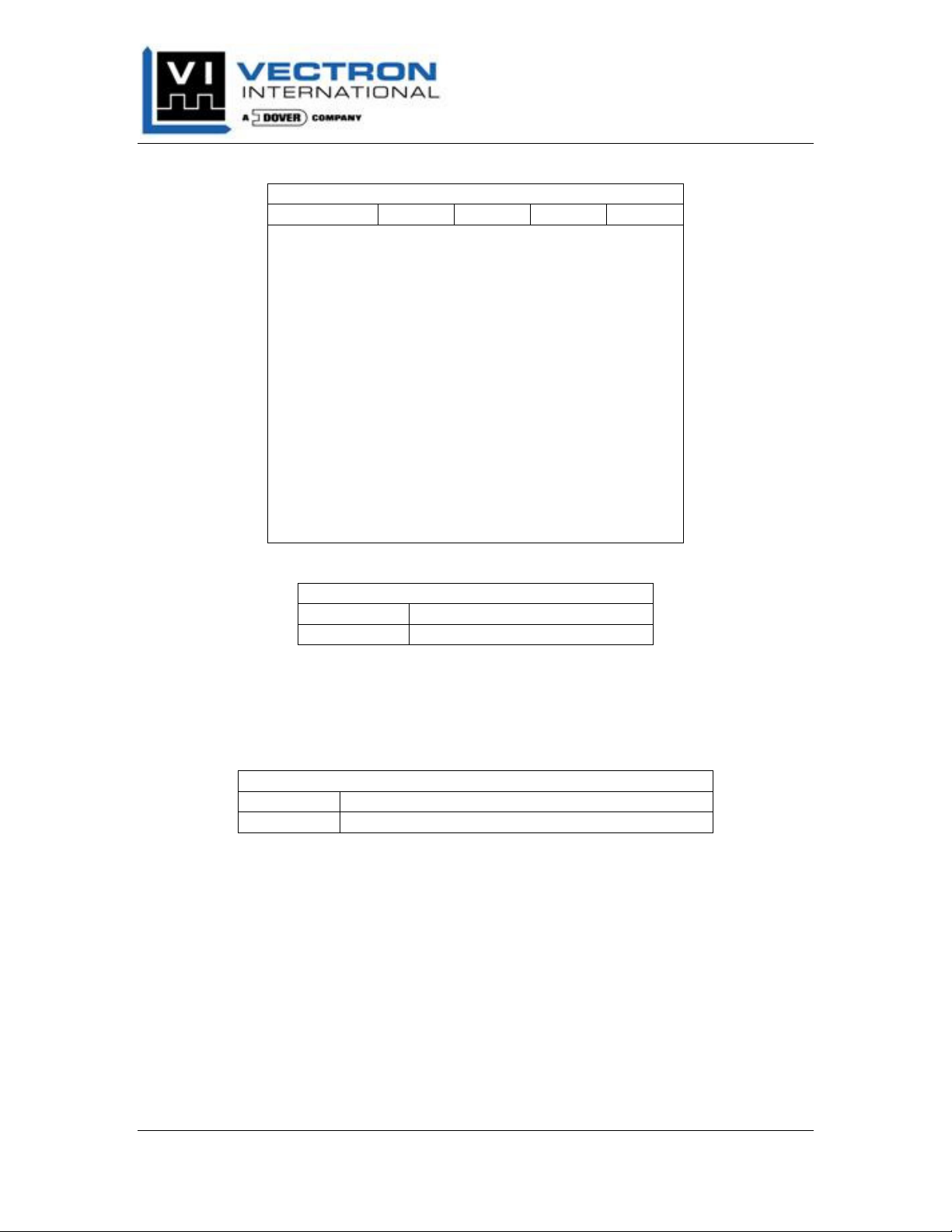
The tables below show the DIP switch settings for node-ID and bit rate configurations for
the CANopen Converter.
Vectron International, Inc. April 2012
267 Lowell Road, Hudson, NH USA Pg. 11
Page 16
VC-2xxx Series Converter
Product Manual
Table 5: CANopen Converter DIP Switch Node IDs
CANopen Converter Node-ID Addressing Table
Node-ID DIP 1 DIP 2 DIP 3 DIP 4
10 OFF OFF OFF OFF
11 OFF OFF OFF
12 OFF OFF
13 OFF OFF
14 OFF
15 OFF
16 OFF
17 OFF
18
19
20
21
22
23
24
25
ON
ON
ON
ON
ON ON
ON ON
ON ON ON
ON ON ON ON
ON
ON
ON ON
ON ON ON
OFF OFF OFF
OFF OFF
OFF
OFF
ON
ON ON
OFF OFF
OFF
ON
ON ON
OFF OFF
OFF
Table 6: CANopen Converter DIP Switch Bit Rate
CANopen Converter Bit Rate, DIP Switch 5
OFF = 125 kbps
ON = 250 kbps
Note: Setting the DIP switches 1-5 to all ON enables the Layer Setting Services to set
Node-ID and bit rate. The CANopen Converter firmware will not configure the node-ID
to 25 and bit rate to 250 kbps.
Table 7: CANopen Converter SIP Switch Bus Termination
CANopen Converter Bus Termination Settings, DIP Switch 6
ON = 120Ω termination enabled
OFF = 120Ω termination disabled
Note: If more than one Converter is used on the same physical CAN bus, then only one
of the CANopen Converters should have the 120 ohm termination resistor set to the ON
position.
ON
OFF
ON
OFF
ON
OFF
ON
OFF
CAN
OPEN LAYER SETTING SERVICES
The CANopen Converter firmware supports the use of the Layer Setting Services. In
order to utilize the LSS, the DIP switches 1-5 must all be ON and the Converter reset by
pushing the Reset switch.
In this mode, the initial Converter Node ID and bit Rate will be the previously stored
EEPROM values. For instance, if the DIP switches 1-5 were OFF, then after changing to
Vectron International, Inc. April 2012
267 Lowell Road, Hudson, NH USA Pg. 12
Page 17
VC-2xxx Series Converter
Product Manual
LSS mode, the Node and ID and Bit rate are 10h, and 125kbps, respectively. These
values remain until the LSS changes the Node ID and Bit Rate.
The Node ID and Bit Rate, set using LSS is stored in EEPROM and will remain until
either the LSS provides new values, or the DIP switches are changed.
The list below shows the supported Node IDs and Bit Rates using the LSS.
IDs 1-127
1000 kbps
800 kbps
500 kbps
Caution should be exercised when using the higher bit rates. Ensure appropriate wire
lengths are used at the higher bit rates.
250 kbps
125 kbps
100 kbps
50 kbps
20 kbps
10 kbps
CAN
OPEN DIAGNOSTIC
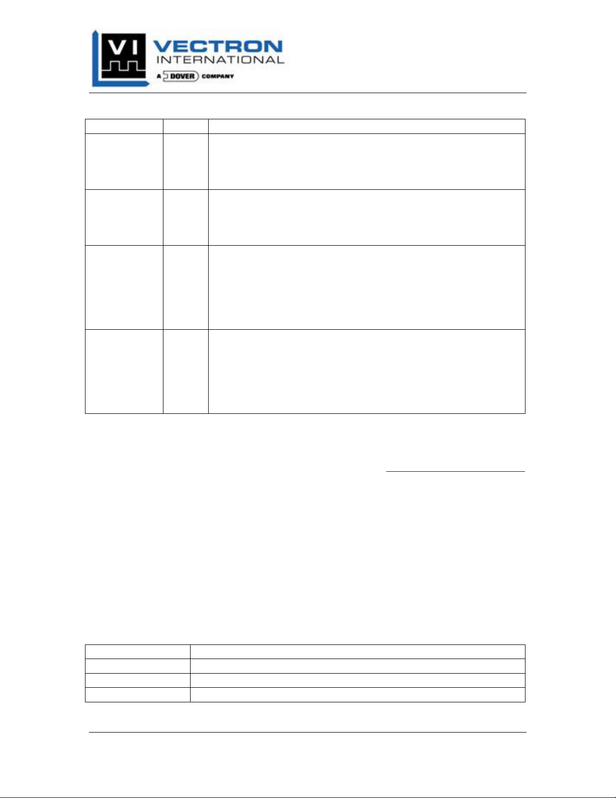
The VC-2010 CANopen Converter has 4 light emitting diodes (LEDs) installed for easy
diagnostic information and can be viewed on the top panel.
Figure 10: VC-2010 CANopen Converter Top Panel
Two LEDs are reserved for Converter Power and Sensor Power, while the other two
CANopen specific, Err and Run. The Err and Run LEDs follow the CiA DS 303
implementation for two LEDs.
Table 8 summaries the functions of the 4 LEDs. Not all LED states are defined for the
Err and RUN LEDs. The reader is referred to the CiA DS 303 draft recommendation for
a complete list of states.
LEDS
Vectron International, Inc. April 2012
267 Lowell Road, Hudson, NH USA Pg. 13
Page 18
VC-2xxx Series Converter
Product Manual
Table 8: VC-2010 CANopen Converter LEDs
LED Name Color Function
Power Red On: Converter is powered, +5VDC is present on circuit
assembly.
Off: Converter is either not powered or a fault exists on
+5VDC regulator circuit.
Sensor Power Red On: +7VDC is present on circuit assembly and available
to Sensor on V+ screw terminal.
Off: Converter is either not powered or a fault exists on
+7VDC regulator circuit.
Err Red On: Bus off;
the CAN controller is bus off.
Blinking: Invalid configuration;
general CAN bus configuration error.
Off: No bus error;
the device is in working condition.
Run Green On: Operational;
the device is in the Operational state.
Blinking: Pre-Operational state;
the device is in the Pre-Operational state.
Off: Bus off;
the CAN controller is bus off.
CAN
OPEN ELECTRONIC DATASHEET FILE
The VisConnect EDS file is available for download on the http://www.SenGenuity.com
website. Please consult the website for the latest release. The revision of the EDS file
must match the firmware revision of the CANopen Converter for proper Converter and
bus functionality.
CAN
OPEN OBJECT DICTIONARY & SUPPORTED FUNCTIONS
The following sections list the supported Object Dictionary Entries on the VC-2010
CANopen Converter. All mandatory entries, per DS301 are supported.
1000h Device Type
This entry describes the CANopen Converter, per DS 401, and it’s functionality. Please
reference DS 401 for more information on this entry.
Name Device Type
Type Unsigned 32
Default Value 00040191h
Access Read Only
Vectron International, Inc. April 2012
267 Lowell Road, Hudson, NH USA Pg. 14
(EDS F
ILE
)
Page 19
VC-2xxx Series Converter
Product Manual
1001h Error Register
The CANopen Converter supports only bit 0 of this entry. When the Error Register value
is 1, the Converter has detected a Generic Error.
Name Error Register
Type Unsigned 8
Default Value 0h
Access Read Only
If value = 0: No errors detected in Converter. Operation is normal.
If value = 1: Error detected in the Converter. Read 6002h Sensor Status
TxPDO for detailed error status information.
1017h Producer Heartbeat Time
The CANopen Converter supports producer heartbeats. The units are multiples of 1
millisecond.
Name Producer Heartbeat Time
Type Unsigned 16
Default Value 0h
Access Read/Write
If value = 0: Converter does not transmit heartbeat message.
If value = 1-65535: Converter transmits heartbeat messages at the value written into
the entry.
If enabled and required, the recommended minimum time for a heartbeat message is 100
ms.
1018h Identity Object
This entry contains information about the Converter, Vendor ID, Product Code, Firmware
Revision number, and Sensor Serial number. All entries are read only.
SUB-I
NDEX
0
The Number of Entries sub-index contains the number of entries in 1018h. The value is
always 4.
Name Number of Entries
Type Unsigned 8
Default Value 4h
Access Read Only
Vectron International, Inc. April 2012
267 Lowell Road, Hudson, NH USA Pg. 15
Page 20
VC-2xxx Series Converter
Product Manual
SUB-I
NDEX
1
The Vendor ID sub-index contains the CiA assigned Vendor ID.
Name Vendor ID
Type Unsigned 32
Default Value 324h
Access Read Only
SUB-I
NDEX
2
The Product Code sub-index contains an unsigned 32 bit integer which may be assigned a
unique OEM number by Vectron. This Product Code should only be used by OEMs.
Name Product Code
Type Unsigned 32
Default Value 0h
Access Read Only
Values read from this sub-index are OEM proprietary.
SUB-I
NDEX
3
The VisConnect Firmware Revision Number sub-index contains an unsigned 32 bit
integer which corresponds to the firmware revision of the VisConnect.
Name VisConnect Firmware Revision Number
Type Unsigned 32
Default Value 3884h
Access Read Only
The revision number is updated at a new release of firmware. The CANopen converter
does not support field firmware updates. At the time of release of this manual the
revision number is 3884h.
SUB-I
NDEX
4
The Sensor Serial Number sub-index contains an unsigned 32-bit integer which is read
from the sensor EEPROM and placed at this sub-index.
Name Sensor Serial Number
Type Unsigned 32
Default Value 0h
Access Read Only
If value = 4xxxxxd: Sensor serial number, read from sensor EEPROM.
If value = 999999d: Cannot read sensor EEPROM and/or no sensor connected.
Vectron International, Inc. April 2012
267 Lowell Road, Hudson, NH USA Pg. 16
Page 21
VC-2xxx Series Converter
Product Manual
1200h Server SDO Parameter
SUB-I
NDEX
0
The Number of Entries sub-index contains the number of entries in 1200h. The value is
always 2.
Name Number of Entries
Type Unsigned 8
Default Value 2h
Access Read Only
SUB-I
NDEX
1
The COB-ID Client to Server (rx) defines the Communication Object Identifier used to
access the Object Dictionary of the CANopen Converter node.
Name COB-ID Client -> Server (rx)
Type Unsigned 32
Default Value Node ID + 00000600h
Access Read Only
SUB-I
NDEX
2
The COB-ID Server to Client (tx) defines the Communication Object Identifier used by
the CANopen Converter node to respond to Object Dictionary requests.
Name COB-ID Server -> Client (tx)
Type Unsigned 32
Default Value Node ID + 00000580h
Access Read Only
1800h, 01, 02 Transmit PDO Parameters
The Transmit PDO Parameters Object Dictionary entry contains the TxPDO parameters
for the three supported TxPDOs in the CANopen Converter. This section covers Object
Dictionary entries 1800h, 1801h, and 1802h.
SUB-I
NDEX
0
The Largest Sub-Index Supported sub-index contains the number of entries in 1800h, 01,
and 02h. The value is always 2.
Name Largest Sub-Index Supported
Type Unsigned 8
Default Value 2h
Access Read Only
Vectron International, Inc. April 2012
267 Lowell Road, Hudson, NH USA Pg. 17
Page 22
VC-2xxx Series Converter
Product Manual
SUB-I
NDEX
1
The COB-ID Used by PDO sub-index defines the COB ID of the TxPDOs.
Name COB-ID Used by PDO
Type Unsigned 32
Default Value 1800h: Node ID + 00000180h
1801h: Node ID + 00000280h
1802h: Node ID + 00000380h
Access Read/Write
SUB-I
NDEX
2
The Transmission Type sub-index defines the transmission types of the TxPDOs. The
value for all three is 255, which is an asynchronous PDO.
Name Transmission Type
Type Unsigned 32
Default Value 1800h: 255d
1801h: 255d
1802h: 255d
Access Read/Write
1A00h, 01, 02 Transmit PDO Mapping
The Transmit PDO Mapping Object Dictionary entry defines where the process data is
stored in a PDO. This section covers Object Dictionary entries 1A00h, 1A01h, and
1A02h.
SUB-I
NDEX
0
The Number of Mapped Application Objects sub-index contains the allowable variables
mapped to the PDO. The maximum value is 8.
Name Number of Mapped Application Objects
Type Unsigned 8
Default Value 1h
Access Read/Write
SUB-I
NDEX
1
The first Mapped Object sub-index defines first TxPDO Object Dictionary Index, subindex, and number of bits to transmit.
Name 1. Mapped Object
Type Unsigned 32
Default Value 1A00h: 60010120h
1A01h: 60020120h
1A01h: 60030120h
Access Read/Write
Vectron International, Inc. April 2012
267 Lowell Road, Hudson, NH USA Pg. 18
Page 23
VC-2xxx Series Converter
Product Manual
Example: A value of 60010120h transmits the 32 bit (20h) PDO at Index 6001h, subindex 01.
SUB-I
NDEX 2 -
These sub-indexes can be used to assign additional mapping to the three default
CANopen Converter TxPDOs.
Name 2 – 8. Mapped Object
Type Unsigned 32
Default Value 1A00h: none
Access Read/Write
If additional mapped object are required, the user is reminded to first disable the TxPDO
by writing a zero to sub-index 0 first. Next, sub-indexes 2 through 8 can be written with
the new mapping. Lastly, write the new number of supported mapped objects to subindex 0.
8
1A01h: none
1A01h: none
6000h Temperature Reading
The Temperature Reading Object Dictionary entry contains the 32 bit floating point
sensor temperature. This asynchronous TxPDO transmits automatically once per second.
SUB-I
NDEX
0
The Number of Objects sub-index contains the number of supported objects for this
entry.
Name Number of Objects
Type Unsigned 8
Default Value 1h
Access Read Only
SUB-I
NDEX
1
The Temperature sub-index contains sensor’s measured temperature in a 32 bit floating
point number. The number format is REAL322 and the temperature units are Celsius.
Name Temperature
Type REAL32
Default Value 0h
Access Read Only
2
The reader is strongly encouraged to review DS301 for the 32 bit conversion to a floating point number.
Vectron International, Inc. April 2012
267 Lowell Road, Hudson, NH USA Pg. 19
Page 24
VC-2xxx Series Converter
Product Manual
Note: Measured values between -50ºC and 150ºC will not be flagged as an error.
If value = -999.: Sensor is disconnected or has measured an invalid sensor
temperature. Read Sensor Status TxPDO for debug information.
6001h Viscosity Reading
The Viscosity Reading Object Dictionary entry contains the 32 bit floating point sensor
acoustic viscosity. This asynchronous TxPDO transmits automatically once per second.
SUB-I
NDEX
0
The Number of Objects sub-index contains the number of supported objects for this
entry.
Name Number of Objects
Type Unsigned 8
Default Value 1h
Access Read Only
SUB-I
NDEX
1
The Viscosity sub-index contains sensor’s measured viscosity in a 32 bit floating point
number. The number format is REAL323 and the viscosity units are Acoustic Viscosity.
Name Temperature
Type REAL32
Default Value 0h
Access Read Only
Note: Values between 0AV and 1e9AV will not be flagged as an error. However, the
typical calibrated sensor range is between 0 and 400AV so caution should be exercised
when the reading exceeds typical application limits.
If value = -999.: Sensor is disconnected. Read Sensor Status TxPDO for debug
information.
6002h Sensor Status
The Sensor Status Object Dictionary entry contains critical information about the status
of the CANopen Converter and Sensor. This asynchronous TxPDO is only transmitted if
an error condition is detected. It is transmitted after the Error Register has updated and
the Temperature and Viscosity TxPDOs are transmitted.
3
The reader is strongly encouraged to review DS301 for the 32 bit conversion to a floating point number.
Vectron International, Inc. April 2012
267 Lowell Road, Hudson, NH USA Pg. 20
Page 25
VC-2xxx Series Converter
Product Manual
SUB-I
NDEX
0
The Number of Objects sub-index contains the number of supported objects for this
entry.
Name Number of Objects
Type Unsigned 8
Default Value 1h
Access Read Only
SUB-I
NDEX
1
The Sensor Status Word contains an unsigned 32-bit integer which can be used help
identify error conditions within the CANopen Converter and Sensor. Each bit, if
implemented, represents a specific error flag. Not all bits are used.
Name Sensor Status Word
Type Unsigned 32
Default Value 0h
Access Read Only
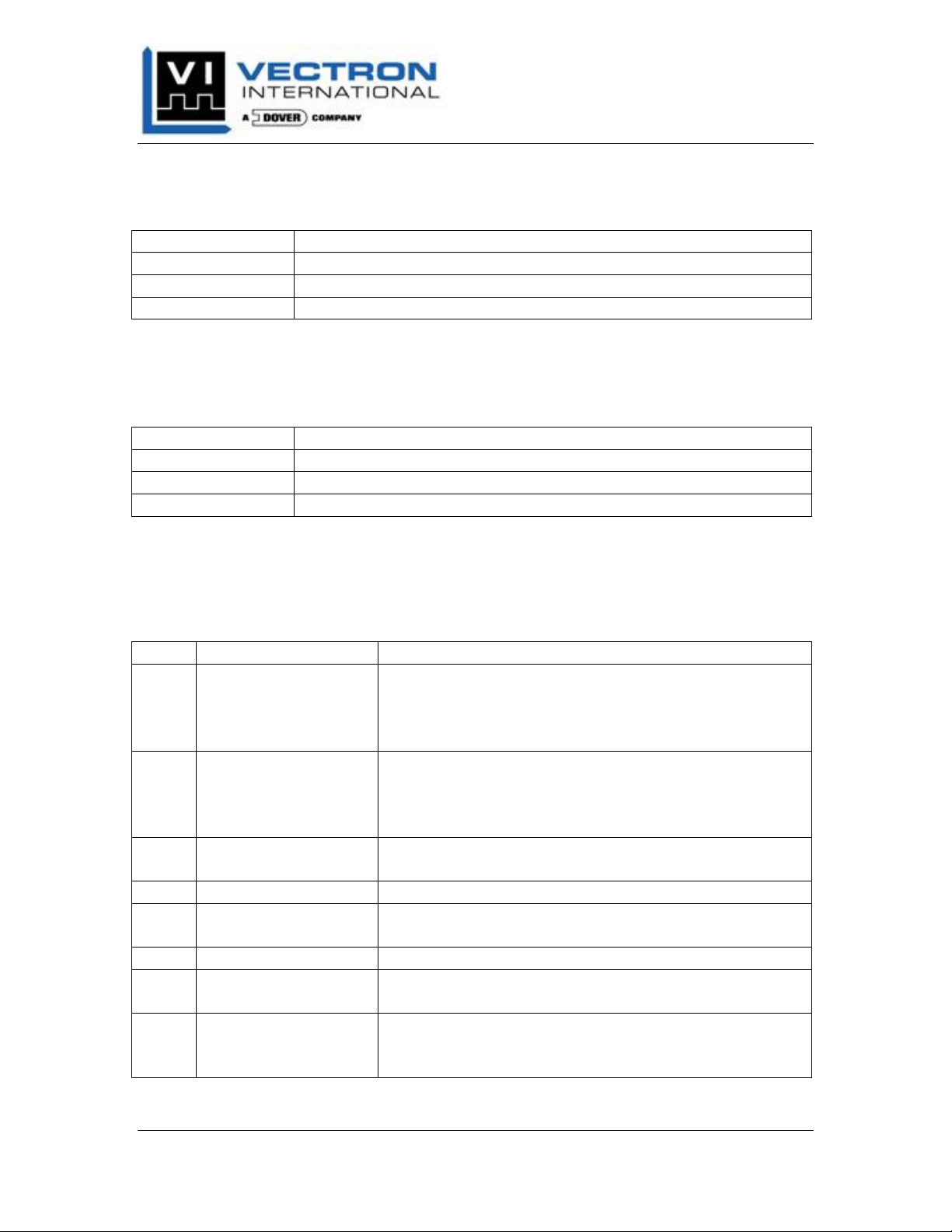
Table 9 below defines the Sensor Status Word for the Sensor CANopen Converter. One
or more bits may be set at a time. The bit is set when the value is 1, otherwise it will be
0.
Table 9: Sensor Status Word
Bit Error Description Meaning
0 Sleep Bit Set The Converter has received an illegal instruction to
SLEEP. The sleep instruction should not occur in
normal operation and indicates a firmware or
microcontroller malfunction.
1 Watchdog Timer The Converter watchdog timer timed out and the
processor reset. The watch dog timer should never
timeout in normal operation and indicates a firmware
or microcontroller malfunction.
2 Reset Instruction The Converter previously received an instruction to
perform a reset.
3-5 reserved Not implemented, always 0
6 FFs Read from
Sensor EEPROM
7 reserved Not implemented, always 0
8 Temp. A/D read
Timeout
9 Temp. A/D overflow
high
The Converter has read all FF's from the sensor's
EEPROM.
The Converter cannot read from the sensor's
temperature A/D and has timed out.
The Converter has detected that the sensor's
temperature A/D has overflowed high in the analog
input voltage.
Vectron International, Inc. April 2012
267 Lowell Road, Hudson, NH USA Pg. 21
Page 26
VC-2xxx Series Converter
Product Manual
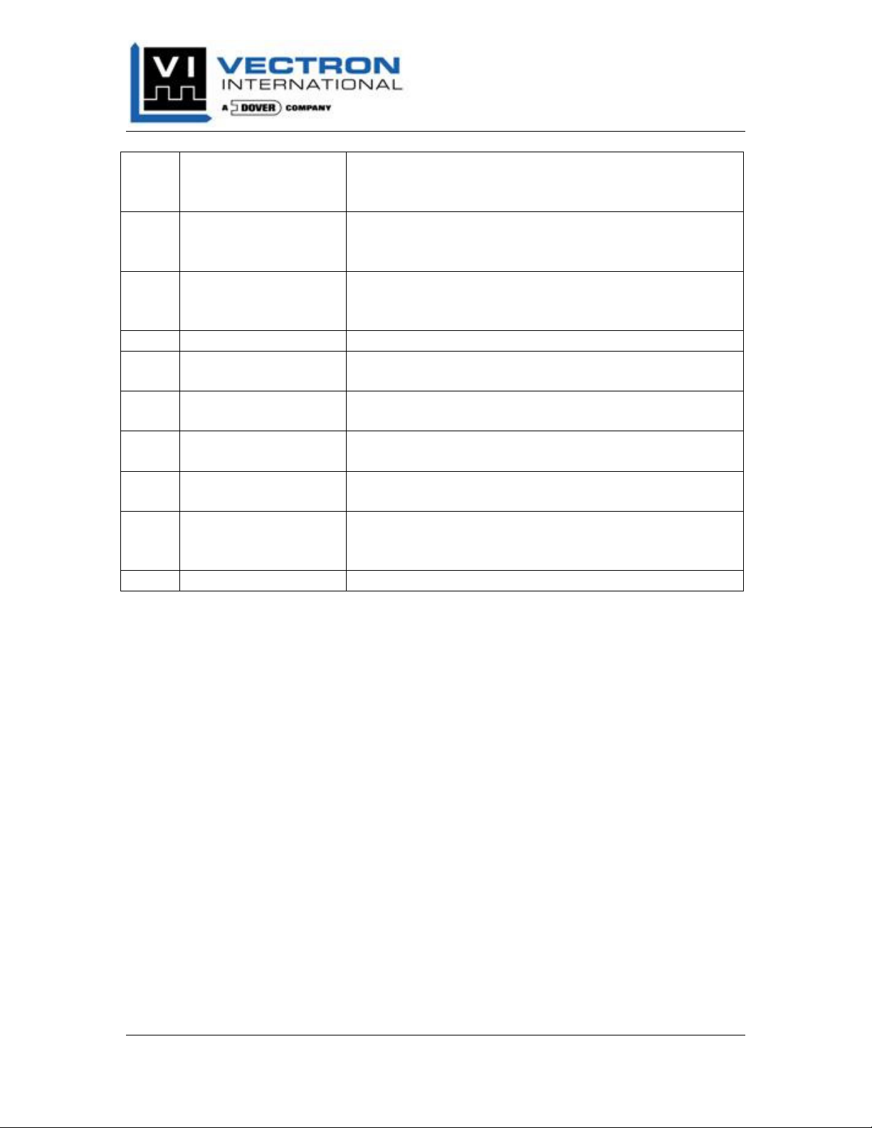
10 Temp. A/D overflow
low
11 Temp. conversion is
above cal range
12 Temp. conversion is
below cal range
13-15 reserved Not implemented, always 0
16 Viscosity A/D read
Timeout
17 Viscosity A/D
overflow high
18 Viscosity A/D
overflow low
19 Viscosity conversion
is above cal range
20 Viscosity conversion
is below cal range
21-31 reserved Not implemented, always 0
Note: If bits 6, 8, and 16 are set to 1, then the Sensor is either disconnected or has
malfunctioned.
The Converter has detected that the sensor's
temperature A/D has overflowed low in the analog
input voltage.
The Converter has detected that the sensor's
temperature A/D reading exceeds the sensor's high
calibration limit of 150C.
The Converter has detected that the sensor's
temperature A/D reading is below the sensor's low
calibration limit of -50C.
The Converter cannot read from the sensor's viscosity
A/D and has timed out.
The Converter has detected that the sensor's viscosity
A/D has overflowed high in the analog input voltage.
The Converter has detected that the sensor's viscosity
A/D has overflowed low in the analog input voltage.
The Converter has detected that the sensor's viscosity
A/D reading exceeds a value of 1e9.
The Converter has detected that the sensor's viscosity
A/D reading is below the sensor's low calibration limit
of 0.
Vectron International, Inc. April 2012
267 Lowell Road, Hudson, NH USA Pg. 22
Page 27

VC-2xxx Series Converter
Product Manual
VC-2010 CANOPEN CONVERTER TROUBLESHOOTING
GUIDE
Use the following section to help identify probable causes for typical troubleshooting
and/or installation issues specific to the CANopen Converter.
Symptom Probable Cause
Power LED not lit Ensure correct range of DC voltage is wired to Converter.
Double check wire polarity (Power/Ground) to screw
terminals.
If using TBUS, double check wire polarity (Power/Ground) to
TBUS connection.
If using TBUS, ensure Converter is seated correctly.
Ensure all terminal connections are tight.
Ensure all wires have been stripped to the correct length.
Sensor Power LED
not lit
Err and Run LEDs
flashing
Err and Run LEDs
flashing and
Converter not
communicating
General bus
problem
Data error in
packets
Ensure correct range of DC voltage is wired to Converter.
Double check wire polarity (Power/Ground) to screw
terminals.
If using TBUS, double check wire polarity (Power/Ground) to
TBUS connection.
If using TBUS, ensure Converter is seated correctly.
Ensure all terminal connections are tight.
Ensure all wires have been stripped to the correct length.
Ensure bus master is connected and initialized.
Double check wiring polarity on CAN_H and CAN_L to the
Converter.
Ensure all terminal connections are tight.
Ensure all wires have been stripped to the correct length.
Check for correct bus Application Layer configuration.
Review CiA DS 303 implementation for two LEDs for full state
descriptions.
Check for correct Bit Rate DIP switch configuration.
Check for correct or duplicate Node ID assignments on other
Converters.
Ensure only one bus termination switch is ON.
Check bus wire lengths vs. Bit rate
Check for bus termination at the bus master.
Ensure only one bus termination switch is ON.
Check for appropriate CAN bus shielding.
Ensure appropriate sensor cable shield grounding between
Converter and Sensor.
Vectron International, Inc. April 2012
267 Lowell Road, Hudson, NH USA Pg. 23
Page 28
VC-2xxx Series Converter
Product Manual
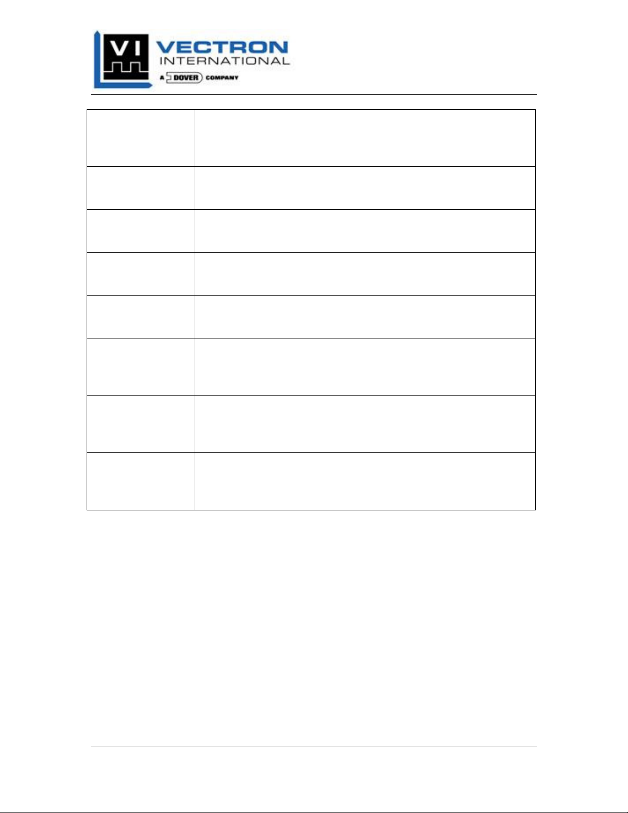
Temperature and
Viscosity TxPDOs
read -999
Sensor Status
TxPDO is
transmitted
Viscosity TxPDO
value jumped to
very high value.
Sensor Status
Reads
00 01 01 40h
Sensor Status
Reads
00 01 01 00h
Sensor Status
Reads
00 08 00 40h
Sensor Status
Reads
00 00 01 40h
Temperature and
Viscosity TxPDOs
intermittently read
-999.
Ensure all wire connections between the Sensor and Converter
exist and all wires stripped and tightened to specification.
Ensure all correct Sensor to Converter wire assignments. See
Table 2.
Review Table 9 to decode the unsigned 32 bit word.
Ensure sensor power (v+) signal is connected.
Ensure sensor face is clean.
Ensure Sensor MISO signal is connected.
Temperature & Viscosity TxPDOs will read -999.
Ensure Sensor cable is seated firmly to Sensor.
Ensure Sensor A1 signal is connected.
Temperature & Viscosity TxPDOs will read -999.
Ensure Sensor A0 & MOSI signal is connected.
Viscosity TxPDOs will read 1e9.
Temperature TxPDO will read normally.
Ensure Sensor SCK signal is connected.
Viscosity TxPDOs will read 160.
Temperature TxPDO will close to -250C.
Check Sensor GND and V+ connections.
Vectron International, Inc. April 2012
267 Lowell Road, Hudson, NH USA Pg. 24
Page 29

VC-2xxx Series Converter
Product Manual
☺ END OF PRODUCT MANUAL ☺
Vectron International, Inc. April 2012
267 Lowell Road, Hudson, NH USA Pg. 25
 Loading...