

Page 1
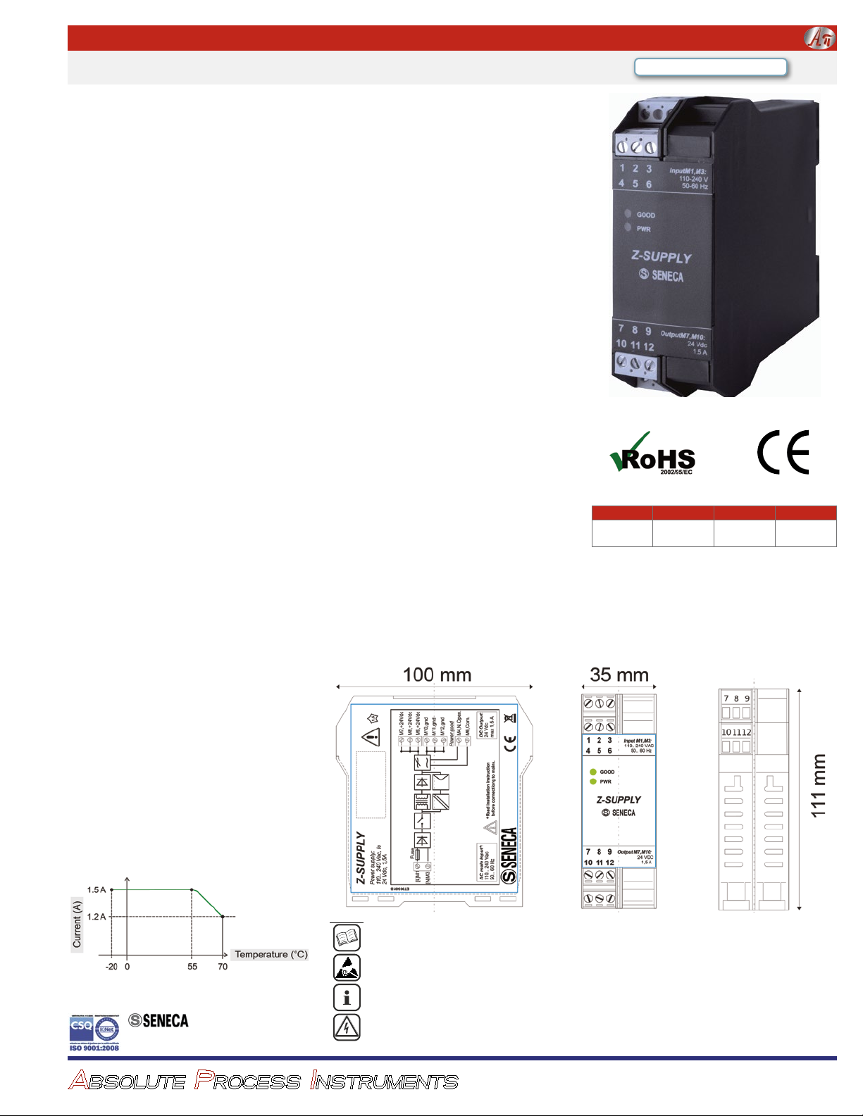
24 VDC Power Supply Z-SUPPLY
Before executing any operation it’s mandatory to read all the contents of this
user manual. Only electrically-skilled technicians can use the module
described in this user manual. It is responsibility of the installer to verify that
the installation complies with safety and wiring standards.
Only the manufacturer is authorized to repair the module or to replace
damaged components.
No warranty is guaranteed in connection with faults resulting from
improper use, from modifications or repairs carried out on the module by
unauthorized personnel, or if the content of this manual is not followed.
This module is designed for connection to hazardous electric voltages. Ignoring
this warning can result in severe personal injury or mechanical damage.
Power: 110-230 VAC or 110-315 VDC
Output: 24 VDC, 1.5 A
O Output Voltage: 24 VDC
O Parallel Redundancy Capable
O Output Current: 1.5 ADC
Description
The Z-SUPPLY is single-phase switching power supply with
AC input rated voltage from 110 VAC to 230 VAC @ 47 to 63
Hz, 0.7 A and DC input rated voltage from 110 VDC to 315
VDC @ 0.7 A.
The Z-SUPPLY provides a 24 VDC ±2% output voltage. Two
Z-SUPPLY units may be connected in parallel for output redundancy, by using the optional IDC10 connector.
The module offers 1.5 A output maximum current and is protected by a 1.25 A, type T (delayed), internal fuse for protection
against over-current and over-voltage conditions.
Input Voltage
110 VAC to 230 VAC, 47-63 Hz, 0.7 A, or
110 VDC to 315 VDC, 0.7 A
Current Consumption
Max 0.7 A @ 100 V, 0.27 A @ 265 V
Internal Fuse
1.25 A, T type (delayed), not user replaceable
External Fuse for Input (Recommended)
2 A, T type (delayed)
Inrush Current Limitation (Plug In)
<25 A
Power Factor
>0.60
Start-Up Voltage With Full Load
~100 VAC (with load: 15 Ω)
Shut-Down Voltage
~90 VAC
Isolation
Up to 3 kV at input
DC Output
24 VDC ±2%, 1.5 A max.
Over-Load Limit Current
1.7 A
Load Regulation
< 1%
Rated ripple
< 50 mVpp
Short-Circuit And Over-Load Protection
Over-load limit with auto reset
Max Resistive Load
15 Ω
Max Capacitive Load
3000 μF
Output Ripple
< 40 mV
Output Regulation
< 1%
Dynamic Regulation
< 1%
Derating curve for output
Starts at 55°C for 0.02 A/K
O "Power Good” Relay Output
O DIN Rail Mount
O Up to 3 kV Input Isolation
Output Relay
Power good relay
Relay type: N.O., 1 A, 30 VDC (resistive)
Relay activation: output voltage > 23.5 VDC
Redundancy
Parallel connection of two Z-SUPPLY's using the optional
IDC10 connector
Indicators
Green LED: output power on indicator
Green LED: power good (>23.5 VDC) indicator
Ambient Operating Range
0 to 50°C operating ambient
Humidity
30-90% RH at 40°C non-condensing
Storage Temperature
–40°C to +85°C
Connectors
IDC with 10 pins for Seneca bus (output redundancy)
Removable screw terminals: pitch 5.08 mm
Housing
Dimensions: 35 mm W x 100 mm H x 111 mm D
Black plastic
IP 20, requires installation in panel or enclosure
Mount on a vertical panel to a horizontal 35 mm DIN rail
Allow 4" (100 mm) above and below housing for air circulation. Allow 1/4" (5 mm) on each side.
Do not block air vents.
To maintain performance, outdoor enclosures must be temperature controlled.
Weight
215 g
Standards
CE
EN 61000-6-4/ 2007 (electromagnetic emission, in industrial
environments)
EN 61000-6-2/ 2005 (electromagnetic immunity, in industrial
environments)
EN 61010-1/ 2001 (safety)
Quick Link: api-usa.com/supply
Model Voltage Max. Current Power
Z-SUPPLY
24 VDC 1.5 A
110-230 VAC
110-315 VDC
Before executing any operation it’s mandatory to read all the contents of this user manual. Only electrically-skilled technicians can use the module described in this user manual. It is responsibility of the installer to verify that the installation
complies with safety and wiring standards.
Only the manufacturer is authorized to repair the module or to replace damaged components.
Turn-off time
15 ms @ 120 VAC, 60 ms @ 230 VAC
ABSOLUTE PROCESS INSTRUMENTS
SENECA s.r.l., PADOVA ITALY
www.seneca.it
No warranty is guaranteed in connection with faults resulting from improper use, from modifications or repairs carried
out on the module by unauthorized personnel, or if the content of this manual is not followed.
This module is designed for connection to hazardous electric voltages. Ignoring this warning can result in severe personal
injury or mechanical damage.
1220 American Way Libertyville, IL 60048
Phone: 800-942-0315 Fax: 800-949-7502
api-usa.com
© 12-17
Page 2
T
It’s important to insert the pins
polarized
IDC10 connector and
For better performance and long life, it is forbidden to obstruct the Z-SUPPLY
ventilation openings (Fig. 2).
ELECTRICAL CONNECTIONS
Power Supply
The electrical connections should only be
carried out when the module is disconnected
and under ESD-safe conditions.
Make sure that the Z-SUPPLY power is
off before wiring or installing.
Before powering the Z-SUPPLY, it is
necessary to correctly phase power (P) and
neutral (N) of the single-phase network, at
screw terminals 1 and 3.
Wire siz
es
0.5 mm2 to 2.5 mm2 (20 AWG to 14 AWG)
VDC O
5
123
4
6
N
P
Fig. 3
GOOD
Input M1,M3:
100.. 260 VAC
50.. 60 Hz
5 mm 5 mm
Fig. 2
ADEQUATE
V
ENTILATION
M
UST BE
P
ROVIDED!
Installation Z-SUPPLY
SIGNAL
LED
STATU S
Good
Constant light
Off
Blinking light
Pwr
Constant light
Off
Before
Through
VDC O
With
Bus
The output voltage equal to 24
enables the
23.5
if a over-loading occurs,
connection
Module Layout
Standards
Standards
EN 61000-6-4/ 2007 (electromagnetic emission, in
industrial environment)
EN 61000-6-2/ 2005 (electromagnetic immunity, in
industrial environment)
EN 61010-1/ 2001 (safety)
Connectors
Connectors
IDC with 10 pins for Seneca bus (output redundancy)
Removable screw terminals: pitch 5.08 mm
Environmental Conditions
Operating temperature
–20°C to +70°C
Humidity
30-90% RH at 40°C not condensing
Storage temperature
–40°C to +85°C
PREPARATION FOR INSTALLATION AND PRECAUTIONS
The module is
improper loads
ET003481B
GOOD
PWR
789
Z-SUPPLY
123
456
Input M1,M3:
110.. 240 VAC
50.. 60 Hz
Output M7,M10:
24 VDC
1,5 A
10 11 12
11
12
10
8
9
7
35 mm
100 mm
For better performance and long
ventilation openings (Fig. 2).
must be installed in a vertical position on a horizontal DIN 46277 rail (fig.1) .
No installation or wiring of the module is allowed while it is powered on.
It is forbidden to install the module near heat-emitting devices.
It is recommended that use and installation are performed by an electricallyskilled technician ensure safe wiring practices, and to avoid
or connections.
The Z-SUPPLY module can achieve a very high temperature, so it is important
to allow proper ventilation and be careful when using it.
INSTALLATION
Power off the module before wiring!
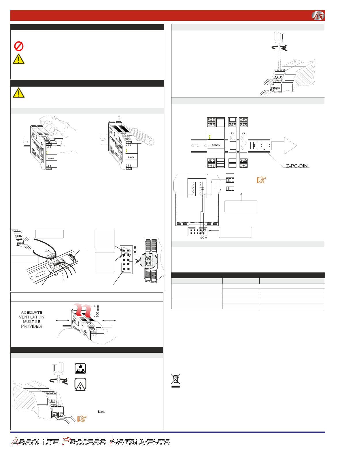
o install/remove the Z-SUPPLY on/from DIN 46277 rail, see Fig.1a and Fig.1b.
Installation / removal from DIN 46277 rail
Fig. 1a
Input M1,M3:
GOOD
Input M1,M3:
GOOD
100.. 240 VAC
PWR
50.. 60 Hz
Z-SUPPLY
Output M7,M10:
24 VDC
1,5 A
INSTALLATION
1) Pull the four latches (placed in the back-
side panel) outwards.
2) Insert the module on the DIN rail.
3) Make sure that the IDC10-connector pins
are inserted in the slot correctly.
4) Press the four latches inwards.
. This connection is facilitated by use of a female/male insertion between
8
9
7
+24VDC
12
11
0 VDC
From OUT of the
Z-SUPPLY:+24 VDC
Z-PC-DIN
the DIN rail slot (Fig 1c and Fig 1d).
From OUT of the
Z-SUPPLY: 0 VDC
P.E .
in the slot correctly because IDC10 connectors are
CANH/A
GNDSHLD
life, it is forbidden to obstruct the Z-SUPPLY
REMOVAL
1) Pull the four latches (placed in the
back-side panel) outwards, using a
screwdriver.
2) Pull the module out gently.
Fig. 1c
GND
CANL/B
Slot
Output
Power
of the
Supply
Z-SUPPLY
AC-
0 V
DC
Output
of the
Power
Z-SUPPLY
Supply
+24 V
DC
AC+
IDC10
PWR
Z-SUPPLY
100.. 240 VAC
Output M7,M10:
50.. 60 Hz
24 VDC
1,5 A
ADEQUATE
V
ENTILATION
MUST BE
PROVIDED!
ELECTRICAL CONNECTIONS
5 mm 5 mm
Fig. 2
Power Supply
Fig. 3
ABSOLUTE PROCESS INSTRUMENTS
5
6
4
123
P
Input M1,M3:
GOOD
100.. 260 VAC
50.. 60 Hz
The electrical connections should only be
carried out when the module is disconnected
and under ESD-safe conditions.
Make sure that the Z-SUPPLY power is
off before wiring or installing.
Before powering the Z-SUPPLY, it is
necessary to correctly phase power (P) and
neutral (N) of the single-phase network, at
screw terminals 1 and 3.
Wire si
zes
0.5 mm2 to 2.5 mm2 (20 AWG to 14 AWG)
N
Fig. 1b
Fig. 1d
24
The output is available on the screw
terminals M7, M8, M9 (+24 VDC) and M10,
M11, M12 (0 VDC) as shown in Fig.4.
The output is protected against current
over-load. If the output is over-loaded,
the Z-SUPPLY protection system will be
activated automatically and output will not
be stable (hiccup).
Protection status is shown through the
«good» LED (blinking light). In this case,
it is necessary to decrease the output
load. When the Z-SUPPLY is restarted, it
will be reset automatically.
24
utput Screw Terminals
Fig. 4
98
+24 VDC
0 VDC
utput
using 24 VDC output through the IDC10 connector, see Fig.1d and in Fig.1c.
the IDC10 connector, the Z-SUPPLY can power up to 15 modules.
123
456
Z-SUPPLY
789
10 11 12
IDC10
Input M1,M3:
GOOD
100.. 240 VAC
PWR
Output M7,M10:
50.. 60 Hz
for Seneca Modules
123
123
456
456
S
S
Run
Pwr
Lnk
Err
Act
Rx
Z-TWS3
789
10 11 12
Z-3AO
789
10 11 12
Tx
24 Vdc
1,5 A
7
1 21 1
UP TO 15
MODULES
Fig. 5
7
9
Fig. 6
8
+
+24 V
10
12
11
0 V
NO
REDUNDANCY
OK
REDUNDANCY
All connection s shown in fig. 6 are
internal, to the Z-SUPPLY.
As you can see in the fig. 6, there is a
diode internally connected at the end
of the IDC10 output, so it is possible
to connect more Z-SUPPLY modules
in parallel ONLY if the redundant
outputs are connected by IDC10.
IT IS FORBIDDEN to connect more
Z-SUPPLY modules in parallel using
the redundant outputs with the screw
terminals (alternatively, connect an
external diode at the end of the
output, for each Z-SUPPLY.
Output Relay and «Power Good»
output voltage only if the voltage between its terminals is greater than
V. If the output voltage is supplied correctly, the LED «good» will be on; otherwise,
s are at screw terminals M4 (normally open) and M6 (common).
the LED «good» will be blinking. The relay contact
VDC is monitored by an internal relay, which
LEDs
MEANING
24 VDC output is ON and regulated
24 VDC output is disabled
Output over-load
24 VDC output is ON
24 VDC output is OFF
Disposal of Electrical & Electronic Equipment (Applicable throughout the European Union
and other European countries with separate collection programs).
This symbol, found on your product or on its packaging, indicates that this product should
not be treated as household waste when you wish to dispose of it. Instead, it should be handed
over to an applicable collection point for the recycling of electrical and electronic equipment.
By ensuring this product is disposed of correctly, you will help prevent potential negative consequences to the environment and human health, which could otherwise be caused by inappropriate disposal of this product. The recycling of materials will help to conserve natural resources.
For more detailed information about the recycling of this product, please contact your local city
office, waste disposal service or the retail store where you purchased this product.
1220 American Way Libertyville, IL 60048
Phone: 800-942-0315 Fax: 800-949-7502
api-usa.com
 Loading...