

Page 1
Z-PC Line
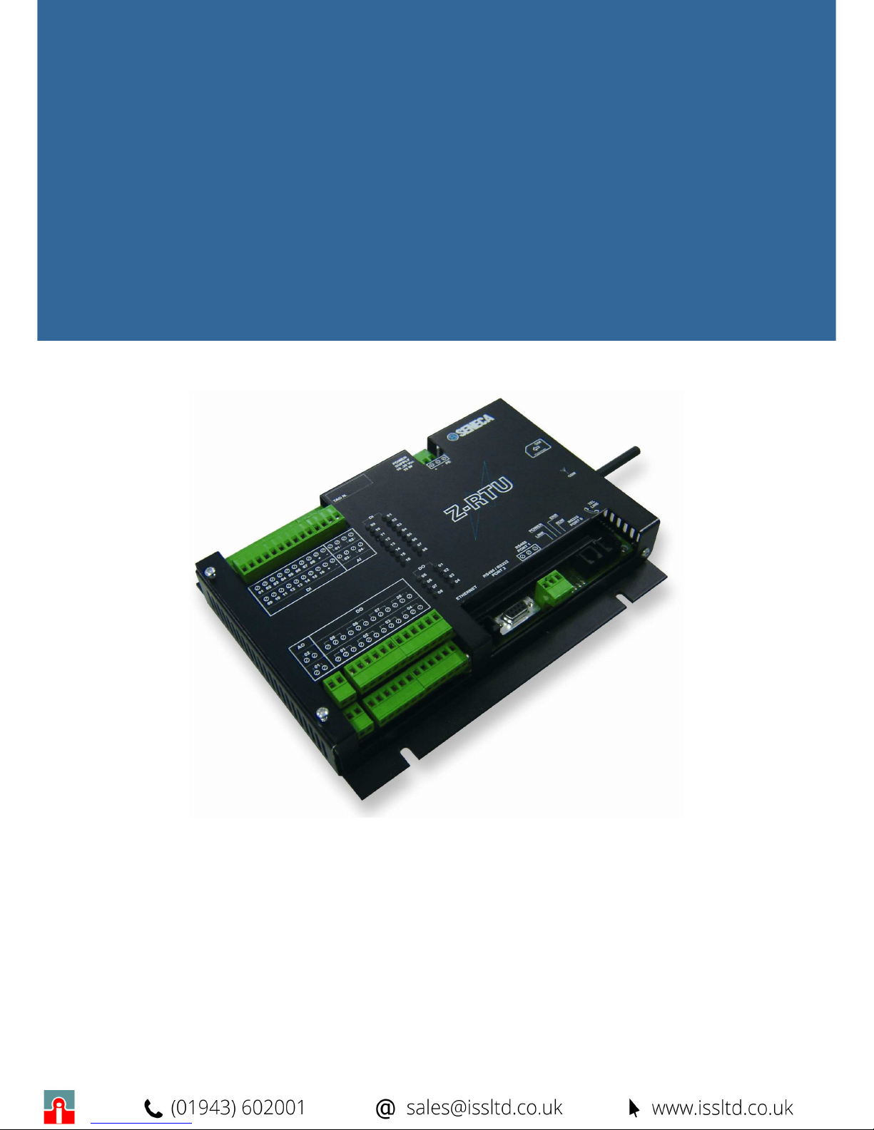
Z-RTU
User Guide
Page 2

MI000920-E
2
INDEX
1
GENERAL FEATURES 3
2
SPECIFICHE TECNICHE 4
2.1
C
OMMUNICATION PORTS
4
2.2
E
LECTRICAL AND THERMOMECHANIC FEATURES
4
2.3
A
NALOG INPUTS FEATURES
5
2.4
A
NALOG INPUTS FEATURES
5
2.5
A
NALOG OUTPUTS FEATURES
5
2.6
D
IGITAL OUTPUTS FEATURES
6
2.7
P
OWER SUPPLY MEASURE
7
2.8
F
LOATING BATTERY FEATURES
7
2.9
I
NTERNAL MODEM
7
2.9.1 GSM/GPRS MODEM 7
2.9.2 PSTN M
ODEM
7
2.10 S
YSTEM PROTOCOLS
7
3
STRUCTURE AND INTERFACE 9
3.1
L
ED INDICATIONS ON
Z-RTU 9
4
ELECTRICAL CONNECTIONS 11
4.1
P
OWER SUPPLY
11
4.2
A
NALOG INPUTS
11
4.3
D
IGITAL INPUTS
11
4.4
A
NALOG OUTPUTS
12
4.5
D
IGITAL OUTPUTS
12
4.6
P
ORT 0
RS232 13
4.7
P
ORT 1
RS485 13
4.8
P
ORT 2
RS485/RS232 14
4.9
DIP-S
WITCHES SETTINGS
14
5
IIC REGISTERS 17
Page 3

MI000920-E
3
1 GENERAL FEATURES
Z-RTU is compact unit, provided of IEC 61131 configurator and software tool for the telecontrol.
Z-RTU is a simple solution to use and install, versatile for remote control, datalogging and I/O
management. With particularly small size (185 x 242 x 36,90 mm) and strong aluminium case, ZRTU offers excellent calculus capabilities (CPU µP RISC 32 bit – 20 MIPS) and memory (Flash
dati 16 MB, RAM 8 MB, 236 bytes retentive memory).
Z-RTU on the base version has several input and output channels (digital and analog). Besides the
I/O density may be doubled through the optional expansion board.
The base configuration manages the following I/O channels, each group galvanically isolated:
• 8 digital inputs (with internal or external power supply)
• 2 analog inputs (14 bit resolution and possibity to select loop power supply )
• 4 digital outputs (SPDT relay), individually isolated.
• 1 analog output (in voltage/current).
Through the software it is possible to visualize the measure in tenths of Volts of the main power
supply.
Z-RTU handles an industrial dual band full type approval GSM modem for the remote
connections, (alternatively, a PSTN modem may be installed) to allow the remote management of
alarms, diagnostics and automatic data sending. For all these features Z-RTU is the ideal solution
for environmental monitoring applications, water and drainage systems, gas control and energy
management.
Page 4
MI000920-E
4
2 SPECIFICHE TECNICHE
In this chapter the technical specifications of the Z-RTU will be illustrated refering to the
communication ports, electrical and thermomechanic features and I/O signals management.
2.1 C
OMMUNICATION PORTS
Z-RTU handles the following communication ports:
• Ethernet Port for Local Network connection.
• PORT 0: RS232 serial port reserved to view the debug of the device functioning.
• PORT 1: RS485 serial port (Modbus RTU Master) to connect with I/O slaves devices.
• PORT 2: serial port configurable as RS232 or RS485.
• Internal Port (not accessible from the user), utilized for the connection with the internal
modem ( GSM or PSTN at choice of the user).
2.2 E
LECTRICAL AND THERMOMECHANIC FEATURES
ELECTRICAL
Power Supply
10-30 Vdc
Max Consumption
15 W max
7 W min
11 W (GSM idle)
Leds Indicators
- Internal power supplies
- GSM modem Status
- Ethernet Link
- Power
- Error
- Run
- Digital Inputs/Outputs
Categoria di installaz.
II
Pollution Degree
2
Protection Index
IP20
THERMOMECHANICS
Functioning Temperature
-10..55°C (advised)
Storage Temperature
-20..+70 °C
Humidity
30..90% a +40 °C (non-condensing)
Dimensions
185 x 242 x 36,90 mm
Weight
875 g
Case
Aluminium
Page 5

MI000920-E
5
Connections
Removable Terminals with section up to
2.5 mm2
2.3 A
NALOG INPUTS FEATURES
Z-RTU may acquire up to 4 analog inputs (2 from the base board and 2 from the expansion).
They have the following features:
Resolution: 14 bits
Precision: 0.1%
1500 Vac isolation from each other and the rest of circuits.
Voltage input: 0÷5 V, 0÷10 V, 1÷5 V, 2÷10 V.
Current input: 0÷20 mA, 4÷20 mA.
Possibility to select loop power supply.
Speed: 5 A/sec..
Protection against overvoltages according to EN61000-4 standard.
Protection against DC overcurrents.
Through the configuration software it is possible to set the input type to acquire (voltage or current)
and the variation range ( 0-5V or 1-5 V, 0-10 V or 2-10 V for voltage signals, 0-20 mA or 4-20 mA
for current signals). Besides it is possible to decide the connection modalities for current inputs: 4
wires (loop power supply disabled) or 2 wires (loop power supply enabled).
2.4 A
NALOG INPUTS FEATURES
Z-RTU may acquire up to 16 digital inputs (8 from the base board and 8 from the expansion board
).
They have the following features:
Internal/external power supply.
1500 Vac isolation from each other and the rest of circuits.
Led indications on the case and on the boards.
Protection from polarity inversion.
Current threshold: 3 mA.
Voltage threshold: 10 V.
Each input handles a16 bits totalizer which allows to make some measuares on the
correspondent digital input. They are separately configurable as counters or for a period measure
on the associated input. If set as counters, they may reach a maximum value of 65535 with
automatic reset in case of overflow. In case of period maesure, they have a resolution of 1ms and
measure digital inputs with frequency up to 100 Hz.
The digital inputs have a common debounce filter (0-250 ms) . So inputs conditions with duration
inferior to the set time, will be ignored (the state and the totalizers will not be modified).
2.5 A
NALOG OUTPUTS FEATURES
Z-RTU may funrnish up to 2 analog outputs (1 from the base board and 1 from the expansion
board) .They have the following electrical features:
1500 Vac isolation from each other and the rest of circuits.
Page 6
MI000920-E
6
Voltage Output : 0÷10 V.
Current Output: 0÷20 mA.
Protection of the user load in case of fault of the output.
Precision: 0.2%
Response Time: 50 ms
The output type (voltage or current) is set through the apposite dip-switches ( paragraph 4.8 ).
2.6 D
IGITAL OUTPUTS FEATURES
Z-RTU manages up to 8 digital outputs ( 4 from the base board, 4 from the expansion board).
4 (+4) SPDT relay contacts (exchange).
Capacity: 5 A-250 Vac.
2500 Vac galvanic isolation of each channel.
Led indication on the case and on the board.
Each output may be configured as stationary or impulsive.
The stationary functioning is the most common where the output follows the correspondent bit.
The impulsive functioning instead allows to activate the output for a period which may be set
through software programming ( 0 to 65535 ms). The output activation occurs on the rising edge of
the correspondent bit, while the deactivation, if anticipated, coincides with the falling edge or the
end of the programmed time, depending on the event which happens before. The impulsive
modality guarantees a greater precision on commanding outputs. Infact the CPU updates the
inputs and the outputs on asynchronous way, with a not costant scanning cycle. So the precision
of the refresh time of the outputs is not guarenteed. For this reason the impulsive functioning mode
has been implemented: if a great precision is required, the activation period and the output
deactivation are fixed unequivocally.
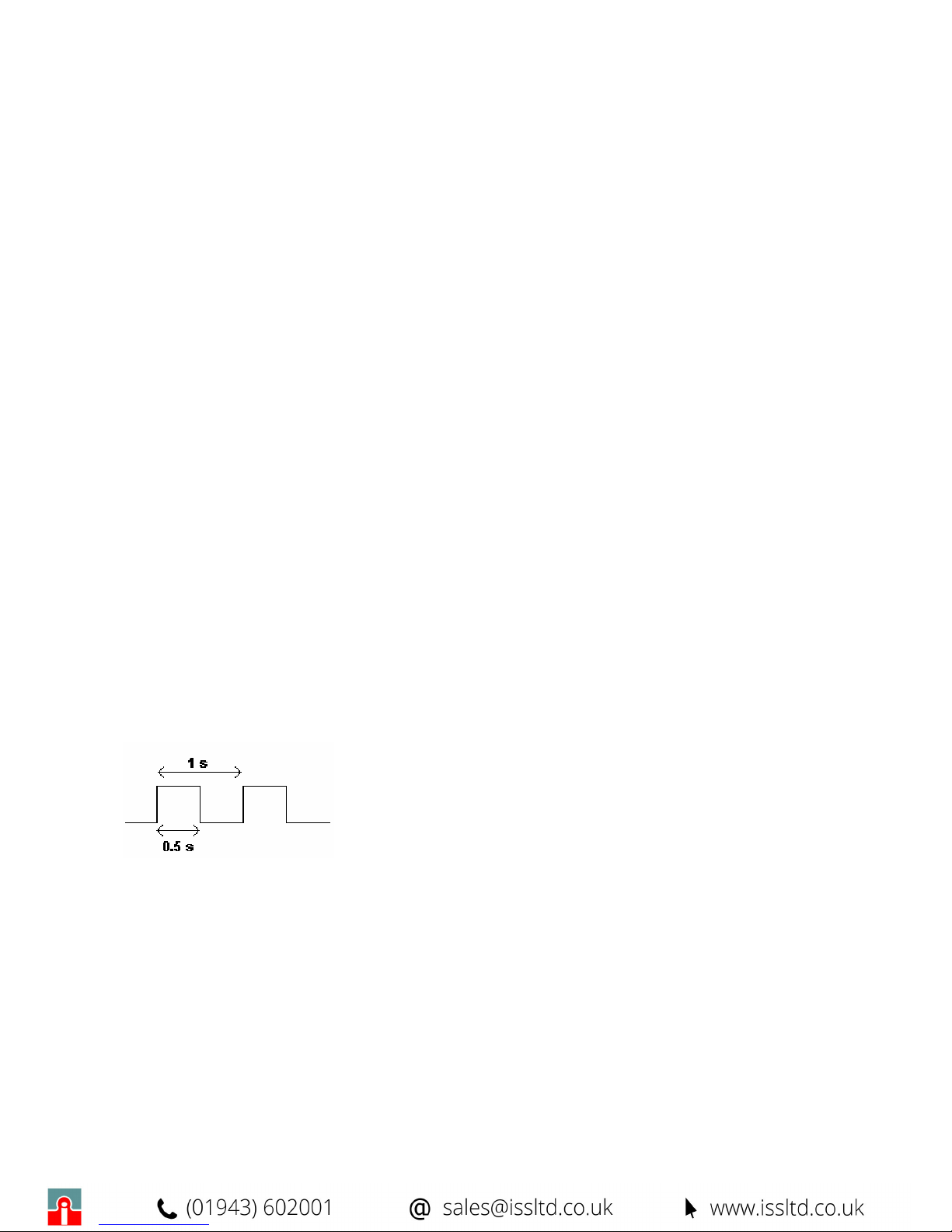
We suppose to have implemented an Isagraf program which pilots the digital output as a square
wave with 1s period and 50% duty cycle. If the output has been configured as stationary, it will
follow the set square wave:
Page 7

MI000920-E
7
2.7 P
OWER SUPPLY MEASURE
Z-RTU manages through software the measure of the power supply voltage which is available
through a IIC register. The measure is on tenths of Volts with admissible range equal to 100-300
V/10 (10-30 V) and 3% precision.
2.8 F
LOATING BATTERY FEATURES
Z-RTU contains a floating battery to allow the functioning of the system clock and the retentive
memory (236 bytes). Its inserting is set through the apposite dip-switch (Paragraph 4.7), Z-RTU is
normally deliverered with the battery not connected.
The duration of the provided battery has the following features:
• At least 2 years: if Z-RTU is turned off and not supplied.
• Up to 10 years: in case of power supply from the network.
2.9 I
NTERNAL MODEM
Z-RTU may have an internal modem, GSM or PSTN, at customer choice.
GSM Modem: it will be necessary to insert a SIM card and the connection to an antenna to avoid
to damage the modem.
PSTN Modem: it is necessary to use a suitable telephone plag to connect to the phone line. It is
important to underline that the PSTN modem owns a protection system against atmospheric
discharges up to 10 kA.
2.9.1 GSM/GPRS MODEM
The GSM modem has the following features:
Dual band GSM 900/1800 MHz (optional: tri-band )
Data, voice, SMS
Speed up to 57,6 kbps
Full type approval
GPRS class 8 (optional: class 10)
Compliant to GSM phase 2/2+
Sensibiliy better then -102 dBm
2.9.2 PSTN Modem
The PSTN modem has the following compatibility features:
ITU-T V.90/ 56 k,
ITU-T V.34 enhanced, V.34, V.32bis, V.32, V.22bis, V22
Bell 212A e 103/113
ITU-T V.21 & V.23
2.10 S
YSTEM PROTOCOLS
Z-RTU may manage the following protocols:
Page 8

MI000920-E
8
• PPP ( Point to Point Protocol ): allows to establish a remote serial connection between
Server and Client.
• HTTP ( HyperText Transfer Protocol ): allows the control, the configuration and the transfer
of files on TCP/IP network, the supervision through OPC Server and OPC Client.
• FTP ( File Transfer Protocol ): allows to perfom operations of upload or download of the
files on the Z-RTU.
• SMTP ( Simple Mail Transfer Protocol ): manages the email sending.
• ModBUS RTU Master / Slave: allows to communicate with I/O modules.
• ModBUS TCP/IP: allows to connect Z-RTU through Ethernet to the local Network.
Page 9
MI000920-E
9
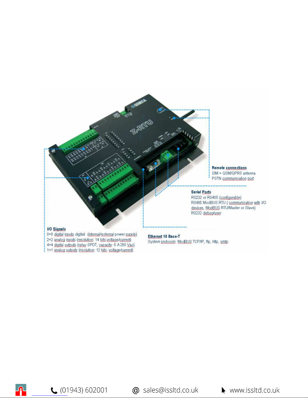
3 STRUCTURE AND INTERFACE
On the following figure the structure of Z-RTU is illustrated, with the position of the I/O and
communication ports.
3.1 L
ED INDICATIONS ON
Z-RTU
The following indicators are present on Z-RTU, to indicate the state or eventual errors:
• LINK: ( Red ) indicates the state of the ETHERNET link.
OFF: ETHERNET link active.
ON: ETHERNET link absent.
• PWR: ( Green ) indicates the presence of the main power supply.
OFF: main power supply absent.
ON: main power supply present.
• ERR: ( Red ) shows an error or fault on the CPU. It may be ON at the ignition of Z-RTU.
OFF: no errors.
ON/FLASHING: error or fault of the CPU.
Page 10

MI000920-E
10
• RUN: (Green ) state of PLC.
FLASHING: PLC (ISaGRAF) program not present
ON: PLC is running.
• GSM: ( Red ) state of GSM connection.
FAST FLASHING: (Period: 1 s and Ton: 0,5 s): Search of the network, not registered o
in turn off phase.
SLOW FLASHING:( Period: 3 s and Ton: 0,35) : Registered and in service.
STEADY ON: optimum link.
Page 11
MI000920-E
11
4 ELECTRICAL CONNECTIONS
4.1 P
OWER SUPPLY
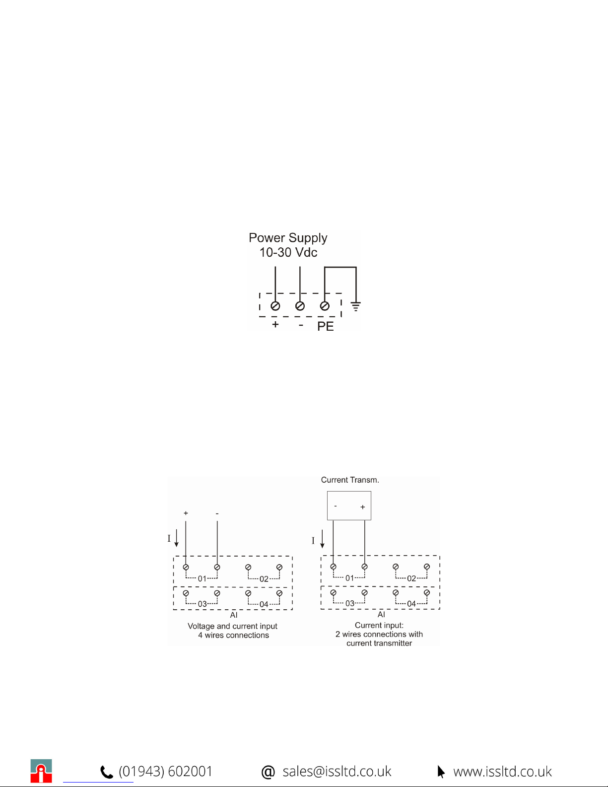
The power supply voltage must be included between 10-30 Vdc. The upper limits must not be
exceeded: this may seriously damage the module. The PE terminal must be connected to
ground either for EMC, I/O channels protections and phone line issues. Z-RTU is protected through
a renewable fuse (capacity: 3A @ 25°C). It is anywa y advisable to insert a similar fuse in series to
the power supply.
4.2 A
NALOG INPUTS
There are two types of connections for the current inputs: 2 or 4 wires.
On the first case the transmitter of the input signal is supplied internally from the device and the fall
of voltage is inferior to 1.2 V; on the second case the transmitter provides an active output and the
provided voltage is approximately 20 Vcc.
The configuration is set by software. On the following figures the terminals 01 and 02 belong to the
base board while the terminals 03 e 04 refer to the expansion board.
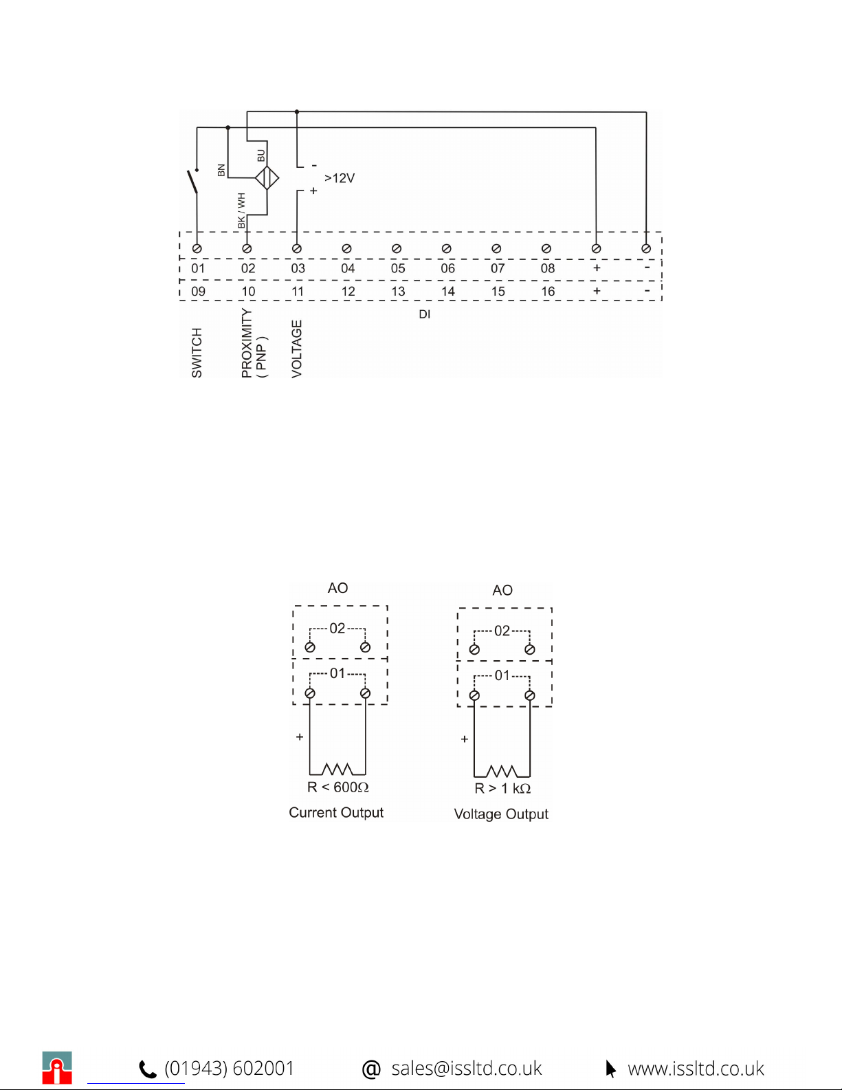
4.3 D
IGITAL INPUTS
The digital inputs may be supplied internally or externally. On the following figure there is an
example of connection with some types of sensor (01-08: Base board, 09-16: Expansion Board):
Page 12
MI000920-E
12
The total current taken from ( + ) terminal does not have to be greater than 40 mA ( the output is
anyway protected from overloads).
4.4 A
NALOG OUTPUTS
The analog outputs may be set through dip-switches (paragraph 4.8) in current (0-20 mA) or
voltage (0-10V).
The connections are the following ( terminals 01: base board, terminals 02: expansion board):
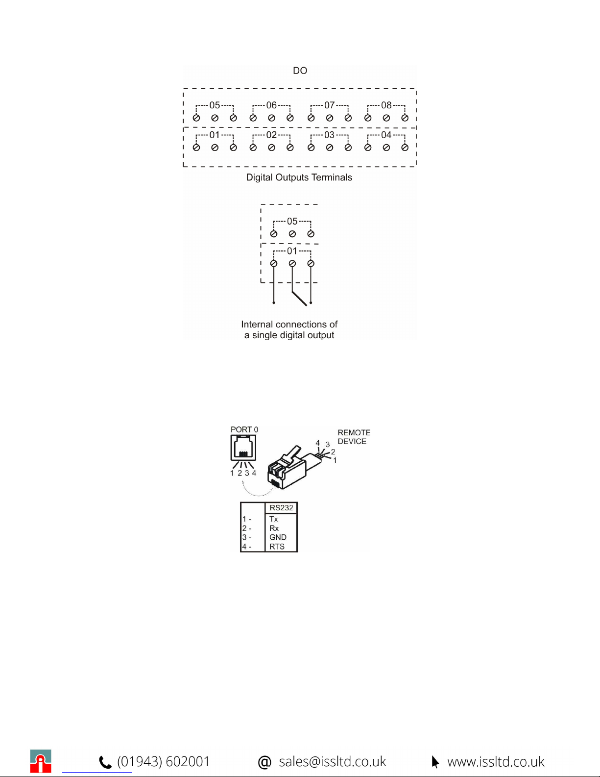
4.5 D
IGITAL OUTPUTS
The connections for the digital outputs ( relays) are the following:
Page 13
MI000920-E
13
4.6 P
ORT 0
RS232
The connections for the communication through the serial port RS232 PORT 0 are the following:
4.7 P
ORT 1
RS485
The connections for the communication through the serial port RS485 PORT 1 are the following:
Page 14
MI000920-E
14
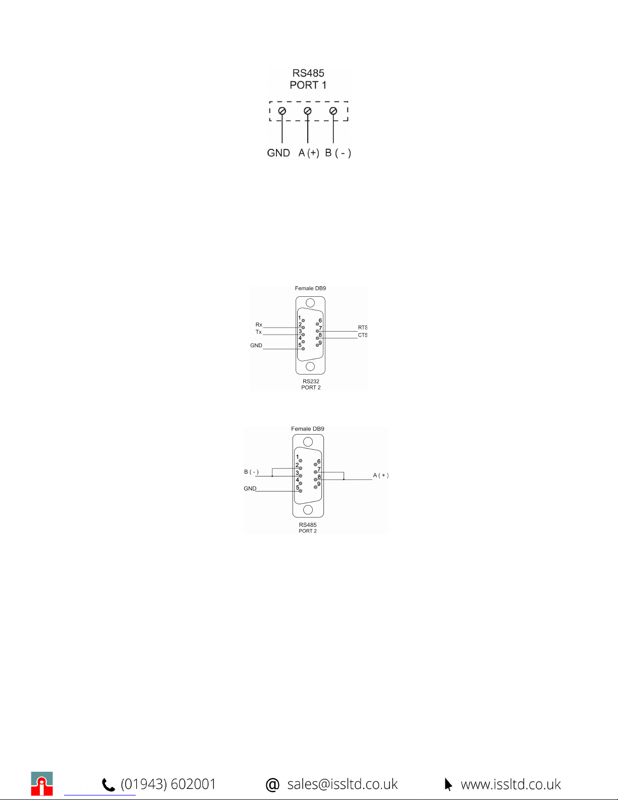
4.8 P
ORT 2
RS485/RS232
PORT 2 may be used as RS232 or RS485, the connections for the communication through the
serial port are the following.
PORT 2 as RS232
PORT 2 as RS485
4.9 DIP-S
WITCHES SETTINGS
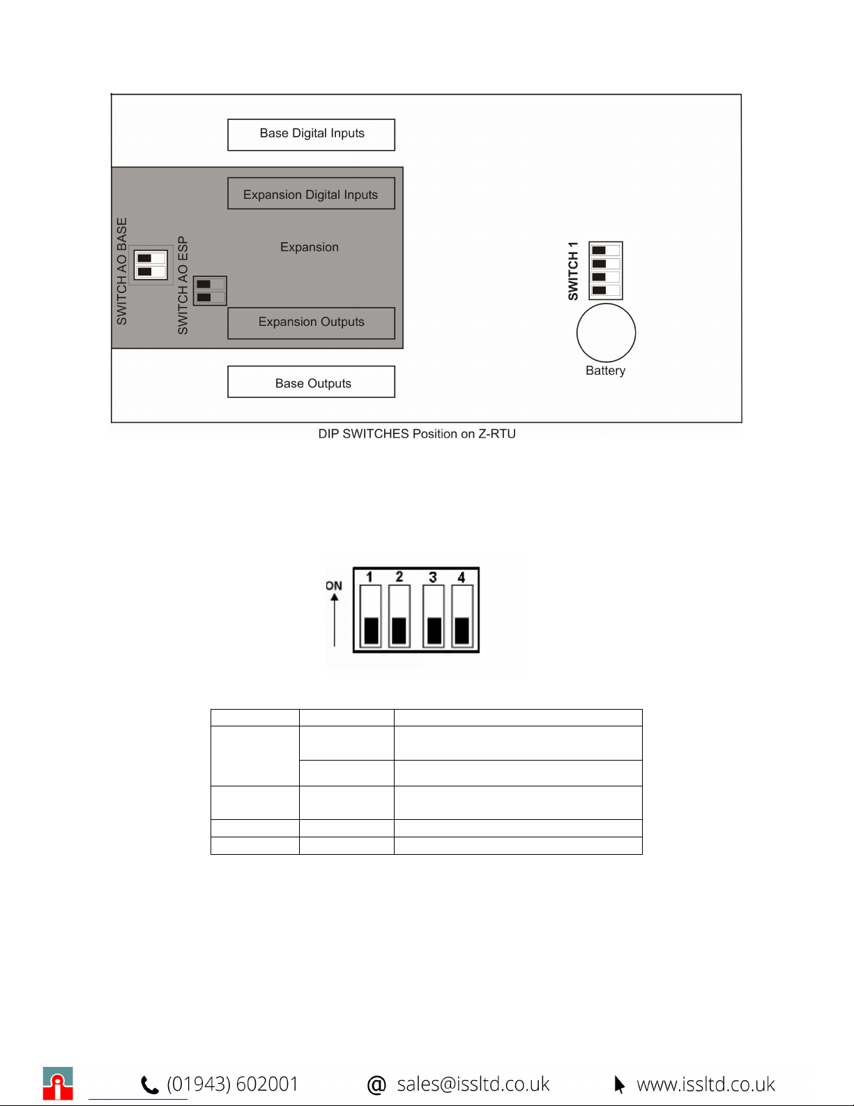
There are three blocks of dip-switches: the first “SWITCH 1” concerns the global management of
the device (battery and serial bus), the remaining: SWITCH AO Base, SWITCH AO ESP
(respectively on the base and expansion boards), sets the features of the analog outputs. On the
below figure there is a scheme of Z-RTU where the position of the dip-switches is localized.
Page 15
MI000920-E
15
The expansion is gray colored while the base is white. The dip switch for the configuration of the
analog output of the base is accessible through a hole on the expansion.
SWITCH 1
Switch 1 is composed of 4 dip-switches:
On the following table, the meaning of the various settings is listed:
Dip-Switch State Funzione
OFF
no Battery Sw1_1
ON Inserts the Battery
Sw1_2 ON The termination of PORT 1 RS485
line is inserted
Sw1_3 ON/OFF Reserved for future use
Sw1_4 ON/OFF Reserved for future use
ANALOG OUTPUTS DIP-SWITCHES ( SWITCH AO Base, SWITCH AO ESP. )
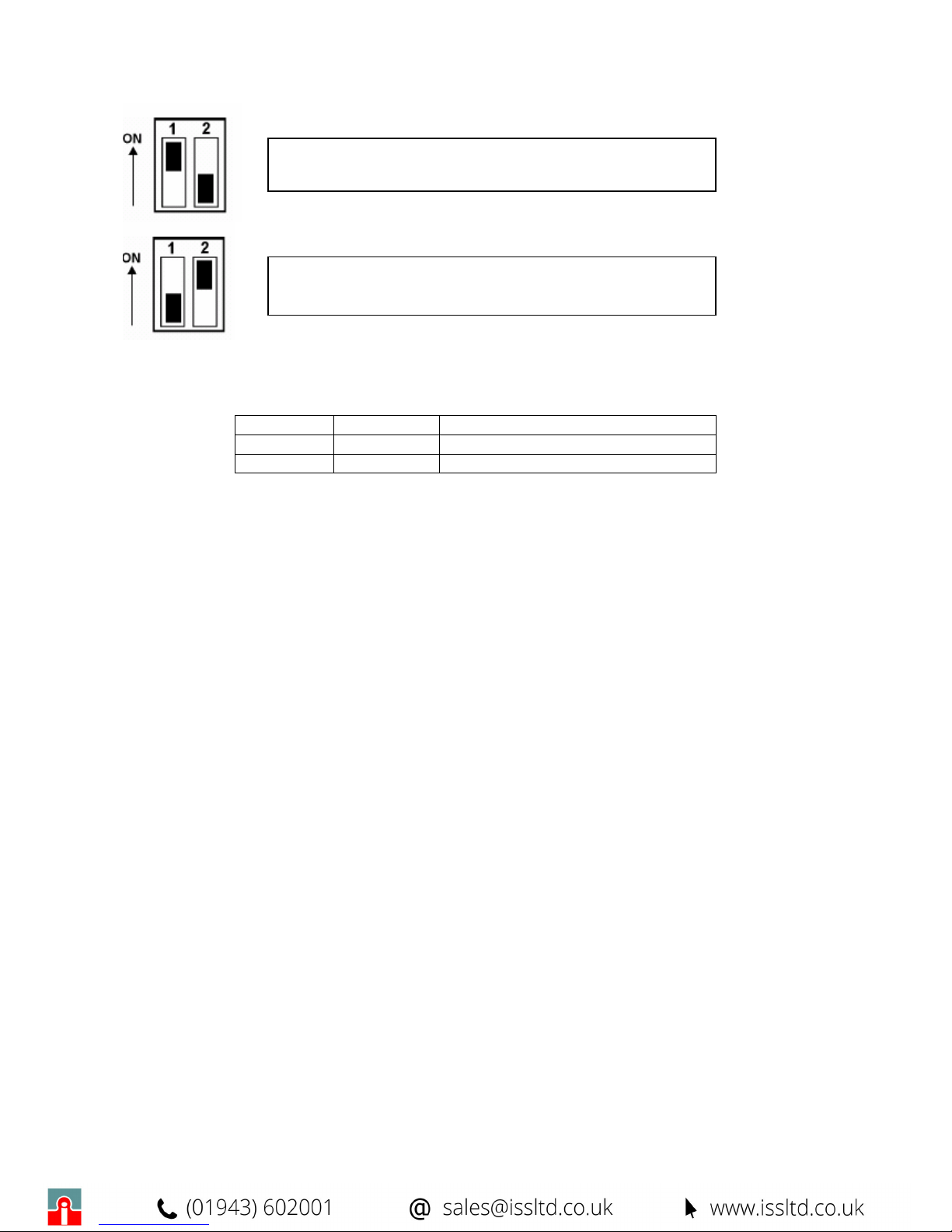
SWITCH AO Base and SWITCH AO ESP set the type of the analog output signal: Voltage or
current. On the below figure the meaning of the combinations for the base board is illustrated (the
settings are identical for the expansion board )
Page 16
MI000920-E
16
The meaning of the combinations is summarized on the below table:
State SW1 State SW2 Function
ON OFF VOLTAGE OUTPUT
OFF ON CURRENT OUTPUT
Sw1: ON, Sw2: OFF:
VOLTAGE ANALOG OUTPUT
Sw1: OFF, Sw2: ON:
CURRENT ANALOG OUTPUT
Page 17
MI000920-E
17
5 IIC REGISTERS
RTU is composed of two equal and independent subsystems, called base board and expansion board
which manage inputs and outputs signals. Both the boards are handled by a microcontroller with IIC slave
function. The base board has address 80, while the expansion board has address 82. Each of them owns
16 bits registers (words), with address from 00 to 30, whose functionalities are the same for both the
boards. The configuration of Z-RTU I/O signals is easily managed through Z-NET3 software, furnished by
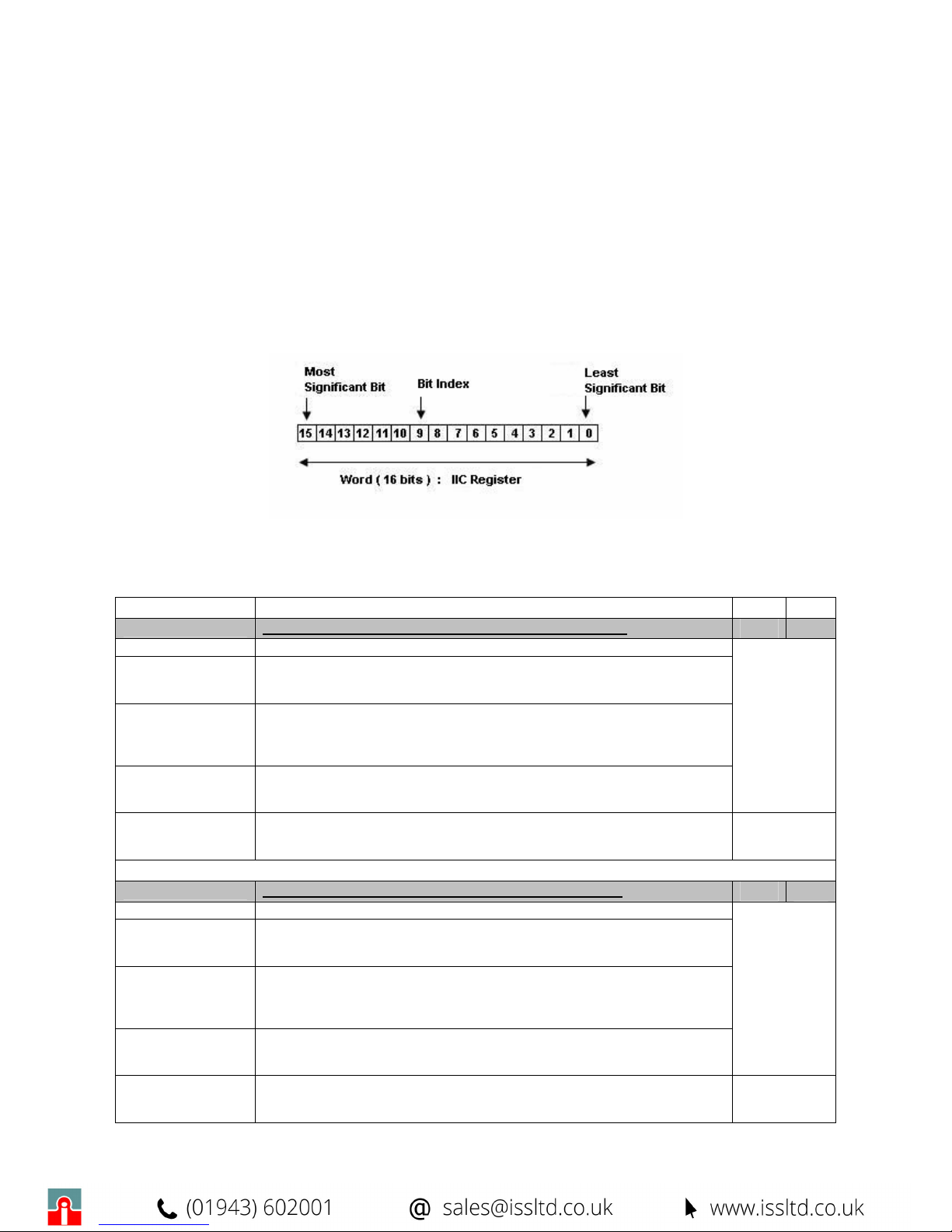
Seneca. The following table lists and describes the Registers present in the boards by referring to
the next data structure:
The notation Bit [x:y] indicates all the bits from x to y: xy. For example Bit [2:1] illustrates the
meaning of the possible combinations of their values.
REGISTER Description ADD R/W
S
ELECTOR AIN
1
Register for the configuration of the analog input 1
00 R/W
Bit [15:4]
Not used
Bit 3
Current Loop selector:
0: disables the power supply of the loop current
1: enables the power supply of the loop current
Bit [2:1]
Input type selector
00: Voltage Input 0-5V or 1-5V
01: Voltage Input 0-10V or 2-10V
10: Current Input 0-20mA or 4-20 mA
Bit 0
Selector of zero's suppression
0: Enables 0-5V, 0-10V or 0-20 mA inputs
1: Enables 1-5V, 2-10V or 4-20 mA inputs
Note
The alteration of the selector associated to the channel causes the
unavailability of the measure until the completion of the successive
cycle of measure.
S
ELECTOR AIN
2
Register for the configuration of the analog input 2
01 R/W
Bit [15:4]
Not used
Bit 3
Current Loop selector:
0: disables the power supply of the loop current
1: enables the power supply of the loop current
Bit [2:1]
Input type selector
00: Voltage Input 0-5V or 1-5V
01: Voltage Input 0-10V or 2-10V
10: Current Input 0-20mA or 4-20 mA
Bit 0
Selector of zero's suppression
0: Enables 0-5V, 0-10V or 0-20 mA inputs
1: Enables 1-5V, 2-10V or 4-20 mA inputs
Note
The alteration of the selector associated to the channel causes the
unavailability of the measure until the completion of the successive
cycle of measure.
Page 18
MI000920-E
18
S
ELECTOR DIN
Register for the configuration of the totalizers associated to the
digital inputs
02 R/W
Bit [15:8]
Not used
Bit 7
Selector Type Measure for DIN8
0:The totalizer associated to digital input 8 is sets as counter
1:Sets the totalizer associated to digital input 8 for a period measure
Bit 6
Selector Type Measure for DIN7
0:The totalizer associated to digital input 7 is sets as counter
1:Sets the totalizer associated to digital input 7 for a period measure
Bit 5
Selector Type Measure for DIN6
0:The totalizer associated to digital input 6 is sets as counter
1:Sets the totalizer associated to digital input 6 for a period measure
Bit 4
Selector Type Measure for DIN5
0:The totalizer associated to digital input 5 is sets as counter
1:Sets the totalizer associated to digital input 5 for a period measure
Bit 3
Selector Type Measure for DIN4
0:The totalizer associated to digital input 4 is sets as counter
1:Sets the totalizer associated to digital input 4 for a period measure
Bit 2
Selector Type Measure for DIN3
0:The totalizer associated to digital input 3 is sets as counter
1:Sets the totalizer associated to digital input 3 for a period measure
Bit 1
Selector Type Measure for DIN2
0:The totalizer associated to digital input 2 is sets as counter
1:Sets the totalizer associated to digital input 2 for a period measure
Bit 0
Selector Type Measure for DIN1
0:The totalizer associated to digital input 1 is sets as counter
1:Sets the totalizer associated to digital input 1 for a period measure
Note
The alteration of the selector associated to the channel causes the
unavailability of the measure until the completion of the successive
cycle of measure or counting.
F
ILTER
Register for the configuration of the filter associated to the
digital inputs.
03 R/W
Bit [15:8]
Not used: to be leaved to 0.
Bit [7:0]
Set the value of the debounce filter, one for all digital inputs Values
from 0 to 255 ms.
S
ELECTOR DOUT
Register for the setting of digital outputs
04 R/W
Bit [15:4]
Not used: to be leaved to 0.
Bit 3
Selector of DOUT4 Type
0: Sets digital output 4 as stationary.
1: Sets digital output 4 as impulsive.
Bit 2
Selector of DOUT3 Type
0: Sets digital output 3 as stationary.
1: Sets digital output 3 as impulsive.
Bit 1
Selector of DOUT2 Type
0: Sets digital output 2 as stationary.
1: Sets digital output 2 as impulsive.
Bit 0
Selector of DOUT1 Type
0: Sets digital output 1 as stationary.
1: Sets digital output 1 as impulsive.
D
URATION
D
OUT
1
Register for the setting of the digital output 1 duration ( if
impusive )
05 R/W
Bit [15:0]
If the digital output 1 has been configured as impulsive, it sets the
time of its duration in msec. It indicates the time during which the
output, as a result of a leading edge, will remain to logical level 1
and after which it will be forced to 0 automatically.
Permitted Values: 0÷65535 ms
Page 19
MI000920-E
19
D
URATION
D
OUT
2
Register for the setting of the digital output 2 duration ( if
impusive )
06 R/W
Bit [15:0]
If the digital output 2 has been configured as impulsive, it sets the
time of its duration in msec. It indicates the time during which the
output, as a result of a leading edge, will remain to logical level 1
and after which it will be forced to 0 automatically.
Permitted Values: 0÷65535 ms
D
URATION
D
OUT
3
Register for the setting of the digital output 3 duration ( if
impusive )
07 R/W
Bit [15:0]
If the digital output 3 has been configured as impulsive, it sets the
time of its duration in msec. It indicates the time during which the
output, as a result of a leading edge, will remain to logical level 1
and after which it will be forced to 0 automatically.
Permitted Values: 0÷65535 ms
D
URATION
D
OUT
4
Register for the setting of the digital output 4 duration ( if
impusive )
08 R/W
Bit [15:0]
If the digital output 4 has been configured as impulsive, it sets the
time of its duration in msec. It indicates the time during which the
output, as a result of a leading edge, will remain to logical level 1
and after which it will be forced to 0 automatically.
Permitted Values: 0÷65535 ms
D
URATION
P
OWRNON
Register for the duration of PwrnON
09 R/W
Bit [15:0]
Set the duration in ms of the impulsive output for GSM module's
ignition.
Default Value: 1000 msec.
M
EASURE
AIN1
Measure in two's complement of the analog signal 1
10 R
Bit [15:0]
Measure of analog input 1, coded in two’s complement.
Admissible Field of measure: -2500÷10000.
The hexadecimal value: 0x8000 indicates that data are not
available.
The hexadecimal value: 0x8001 indicates ADC failure.
M
EASURE
AIN2
Measure in two's complement of the analog signal 2
11 R
Bit [15:0]
Measure of analog input 2, coded in two’s complement.
Admissible Field of measure: -2500÷10000.
The hexadecimal value: 0x8000 indicates that data are not
available.
The hexadecimal value: 0x8001 indicates ADC failure.
M
EASURE DIN
1
Measure of the totalizer associated to the digital input 1
12 R
Bit [15:0]
16 bits totalizer, associated to digital input 1. It may indicate the
counting or the period in ms of digital input 1, depending on the
setting of SELECTOR DIN register.
M
EASURE DIN
2
Measure of the totalizer associated to the digital input 2
13 R
Bit [15:0]
16 bits totalizer, associated to digital input 2. It may indicate the
counting or the period in ms of digital input 2, depending on the
setting of SELECTOR DIN register.
M
EASURE DIN
3
Measure of the totalizer associated to the digital input 3
14 R
Bit [15:0]
16 bits totalizer, associated to digital input 3. It may indicate the
counting or the period in ms of digital input 3, depending on the
setting of SELECTOR DIN register.
Page 20
MI000920-E
20
M
EASURE DIN
4
Measure of the totalizer associated to the digital input 4
15 R
Bit [15:0]
16 bits totalizer, associated to digital input 4. It may indicate the
counting or the period in ms of digital input 4, depending on the
setting of SELECTOR DIN register.
M
EASURE DIN
5
Measure of the totalizer associated to the digital input 5
16 R
Bit [15:0]
16 bits totalizer, associated to digital input 5. It may indicate the
counting or the period in ms of digital input 5, depending on the
setting of SELECTOR DIN register.
M
EASURE DIN
6
Measure of the totalizer associated to the digital input 6
17 R
Bi t[15:0]
16 bits totalizer, associated to digital input 6. It may indicate the
counting or the period in ms of digital input 6, depending on the
setting of SELECTOR DIN register.
M
EASURE DIN
7
Measure of the totalizer associated to the digital input 7
18 R
Bit [15:0]
16 bits totalizer, associated to digital input 7. It may indicate the
counting or the period in ms of digital input 7, depending on the
setting of SELECTOR DIN register.
M
EASURE DIN
8
Measure of the totalizer associated to the digital input 8
19 R
Bit [15:0]
16 bits totalizer, associated to digital input 8. It may indicate the
counting or the period in ms of digital input 8, depending on the
setting of SELECTOR DIN register.
S
TATUS
DIN
Register of digital inputs status
20 R
Bit [15:8]
Not used
Bit 7
Status of digital input 8
0: Indicates that the status of the digital input 8 is OFF.
1: Indicates that the status of the digital input 8 is ON.
Bit 6
Status of digital input 7
0: Indicates that the status of the digital input 7 is OFF.
1: Indicates that the status of the digital input 7 is ON.
Bit 5
Status of digital input 6
0: Indicates that the status of the digital input 6 is OFF.
1: Indicates that the status of the digital input 6 is ON.
Bit 4
Status of digital input 5
0: Indicates that the status of the digital input 5 is OFF.
1: Indicates that the status of the digital input 5 is ON.
Bit 3
Status of digital input 4
0: Indicates that the status of the digital input 4 is OFF.
1: Indicates that the status of the digital input 4 is ON.
Bit 2
Status of digital input 3
0: Indicates that the status of the digital input 3 is OFF.
1: Indicates that the status of the digital input 3 is ON.
Bit 1
Status of digital input 2
0: Indicates that the status of the digital input 2 is OFF.
1: Indicates that the status of the digital input 2 is ON.
Bit 0
Status of digital input 1
0: Indicates that the status of the digital input 1 is OFF.
1: Indicates that the status of the digital input 1 is ON.
V
ALUE
PWM
Value of the analog output
21 R/W
Bit [15:0]
Set the value of the analog output
Permitted Range: 0÷4000 correspondent to 0÷10 V or 0÷ 20 mA
V
ALUE DOUT
Register for the setting of digital outputs values
22 R/W
Bit [15:4]
Not utilized, set to 0.
Page 21
MI000920-E
21
Bit 3
Value of digital output 4
0: Forces the digital output 4 to OFF.
1: Forces the digital output 4 to ON.
Bit 2
Value of digital output 3
0: Forces the digital output 3 to OFF.
1: Forces the digital output 3 to ON.
Bit 1
Value of digital output 2
0: Forces the digital output 2 to OFF.
1: Forces the digital output 2 to ON.
Bit 0
Value of digital output 1
0: Forces the digital output 1 to OFF.
1: Forces the digital output 1 to ON.
M
EASURE PWR
F
Measure of the main Power Supply
23 R
Bit [15:0]
Indicates the measure of the Power Supply in 1/10 V
Permitted Range of measure : 100-300.
V
ALUE AUXOUT
Register for the setting of PwrOn digital value
24 R/W
Bit [15:1]
Not utilized. To be leaved to 0.
Bit 0
Digital PwrOn
0: OFF
1: ON
C
ALIBRATION
AIN1
Register for the calibration of analog input 1
25 R/W
Note: Already set up from the provider, not modify.
C
ALIBRATION
AIN2
Register for the calibration of analog input 2
26 R/W
Note: Already set up from the provider, not modify.
O
FFSET
PWM
Register for the setting of the offset of PWM analog output
27 R/W
Bit [15:0]
Set the offset of PWM output, coded in two's complement
.
P
ERIOD
PWM
Register for the setting of the period of PWM analog output
28 R/W
Bit [15:0]
Set the period in msec of PWM output.
C
ALIBRATION
P
WRF
Register for the calibrazione of power supply's measure.
29 R/W
Note: Already set up from the provider, not modify.
P
ASSWORD
Register for the definition of the password for the access to the
calibration
30 R/W
Note: The calibration operations already have been carried out from the
supplier.
 Loading...